Page 841 of 1449

MANUAL TRANSMISSION - Troubleshooting 22A-33
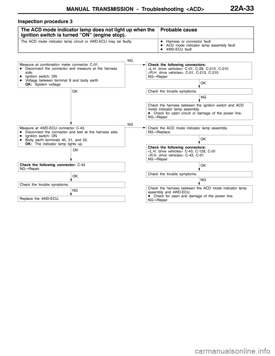
Inspection procedure 3
The ACD mode indicator lamp does not light up when the
ignition switch is turned “ON” (engine stop).
Probable cause
The ACD mode indicator lamp circuit or 4WD-ECU may be faulty.DHarness or connector fault
DACD mode indicator lamp assembly fault
D4WD-ECU fault
OK OK OKOK
NG
OK
NG
NG
NG
Check the harness between the ACD mode indicator lamp
assembly and 4WD-ECU.
DCheck for open and damage of the power line.
NG→Repair
Replace the 4WD-ECU.
Measure at 4WD-ECU connector C-43.
DDisconnect the connector and test at the harness side.
DIgnition switch: ON
DBody earth terminals 40, 51, and 52.
OK:The indicator lamp lights up.
Check the trouble symptoms.
Measure at combination meter connector C-01.
DDisconnect the connector and measure at the harness
side.
DIgnition switch: ON
DVoltage between terminal 9 and body earth
OK:System voltageCheck the following connectors:
C-01, C-29, C-213, C-210
C-01, C-213, C-210
NG→Repair
Check the trouble symptoms.
Check the ACD mode indicator lamp assembly.
NG→Replace
Check the harness between the ignition switch and ACD
mode indicator lamp assembly.
DCheck for open circuit or damage of the power line.
NG→Repair
Check the following connectors:
C-43, C-128, C-01
C-43, C-01
NG→Repair
OK
NG
Check the trouble symptoms.
Check the following connector:C-43
NG→Repair
Page 873 of 1449

MANUAL TRANSMISSION OVERHAUL -Sealants22B-7
SEALANTS
TRANSMISSION
ItemsSpecified sealants
Clutch housing and transmission case contact surfaceMITSUBISHI genuine sealant Part
No MD997740orequivalent
Control housing and transmission case contact surface
No.MD997740or equivalent
Under cover and transmission case contact surface
Air breather3M SUPER WEATHERSTRIP No.8001 or
equivalent
Center differential drive gear bolt3M STUD Locking No.4170 or equivalent
FORM-IN-PLACE GASKET (FIPG)
FIPG is used for several members of this transmission. With this gasket, caution is required to the application
amount, application procedure and state of the application surface so that the performance is sufficiently
attained.
If sufficient gasket is not applied, leaks could occur, and if too much is applied, the gasket could protrude
and plug or restrict the oil flow passage. Thus, to prevent leaks from the joined sections, it is absolutely
necessary to evenly apply the correct amount.
DISASSEMBLY
The parts assembled with FIPG can be easily disassembled without special means. However, in some
cases, the sealant on the contact surfaces must be broken by lightly tapping with a wood hammer or
similar tool.
Washing the gasket surface
Completely remove all matters adhered on the contact surfaces with a gasket scraper. Confirm that the
FIPG application surface is smooth. There must be no grease or foreign matter on the contact surfaces.
Always remove the old FIPG that has entered the mounting holes and screw holes.
APPLICATION PROCEDURES
Apply an even coat of FIPG within the predetermined radius (1.5±0.3 mm). Completely cover the areas
around the mounting holds. The FIPG can be wiped off if it has not hardened. Install at the set position
while the FIPG is still wet (within 10 minutes). When installing, make sure that the FIPG does not get
on areas other than the required areas. After installing, do not subject the application areas to oil or
water or start operation until the FIPG has sufficiently hardened (approx. one hour).
The FIPG application procedures differ according to the member, so follow the procedures given in this
manual and apply the FIPG.
Page 877 of 1449
MANUAL TRANSMISSION OVERHAUL -Tightening Torque22B-11
TIGHTENING TORQUE
TRANSMISSION
ItemsTightening torque N•m
Under cover mounting bolt6.9±1
Interlock plate bolt30±3
Clutch housing and transmission case tightening bolt44±5
Clutch release bearing retainer mounting bolt9.8±2
Control housing mounting bolt18±3
Shift cable bracket mounting bolt18±3
Speedometer gear mounting bolt3.9±1
Stopper bracket mounting bolt18±3
Select lever mounting bolt18±3
Select lever mounting nut11±1
Center differential drive gear mounting bolt132±5
Backup light switch32±2
Poppet spring32±2
Reverse idler gear shaft mounting bolt48±5
Roll stopper bracket mounting bolt69±9
TRANSFER
ItemsTightening torque N•m
Transfer cover mounting bolt23±3
Transmission and transfer tightening bolt69±9
Page 881 of 1449
MANUAL TRANSMISSION OVERHAUL -Transmission22B-15
TRANSMISSION
DISASSEMBLY AND REASSEMBLY
3
69±9N•m18±3N•m
69±9N•m18±3N•m
69±9N•m 32±2N•m
32±2N•m
3.9±1N•m
6
2
37
8 59
110
4
Disassembly steps
1. Transfer
2. O-ring
3. Roll stopper bracket
4. Shift cable bracket
5. Select lever"JA6. Speedometer gear
7. Backup light switch
8. Gasket
"IA9. Poppet spring
"HA10. Gasket
Page 887 of 1449

MANUAL TRANSMISSION OVERHAUL -Transmission22B-21
"GACONTROL HOUSING INSTALLATION
Apply sealant at the positions of the transmission case shown
in the illustration.
Sealant
Specified sealant:
MITSUBISHI genuine sealant Part No.MD997740 or
equivalent
Caution
Evenly squeeze out the agent so that it is not insufficient
or excessive.
"HASPEEDOMETER GEAR INSTALLATION
Apply transmission oil on the O-ring for the speedometer
gear.
Transmission oil
Specified oil:
MITSUBISHI genuine “DIA-QUEEN” multi gear oil
<75W/85W> or equivalent
"IASELECT LEVER INSTALLATION
Apply grease on the sliding section of the select lever shoe’s
control shaft.
Grease
Specified grease:
MITSUBISHI genuine grease Part No.0101011 or
equivalent
"JAO-RING INSTALLATION
Apply transmission oil on the O-ring.
Transmission oil
Specified oil:
MITSUBISHI genuine “DIA-QUEEN” multi gear oil
<75W/85W> or equivalent
INSPECTION
BACKUP LIGHT SWITCH
Check the continuity between the terminals.
ItemsContinuity
Switch pressedContinuity not established
Switch releasedContinuity established
Control shaft
Select
lever
shoe
Page 960 of 1449

REAR AXLE -Troubleshooting REAR AXLE -Troubleshooting 27B-14
INSPECTION CHART FOR TROUBLE SYMPTOMS
Trouble symptomInspection
procedure No.Reference
page
Communication between MUT-IIand the whole system is not possible.1Refer to
GROUP22
Communication between MUT-IIand 4WD-ECU is not possible.2
GROUP22.
3 ACD mode indicator lamps do not light up when the ignition key is turned to “ON”
(engine stationary).3
3 ACD mode indicator lamps remain lit up after the engine has started.4
AYC is inoperative.
Unable to start or accelerate on slippery road surfaces.527B-14
Rear tires are noisy during low-speed cornering.
Vehicle skews.627B-15
Noise is produced from the torque transfer differential during turning.727B-15
INSPECTION PROCEDURE FOR TROUBLE SYMPTOMS
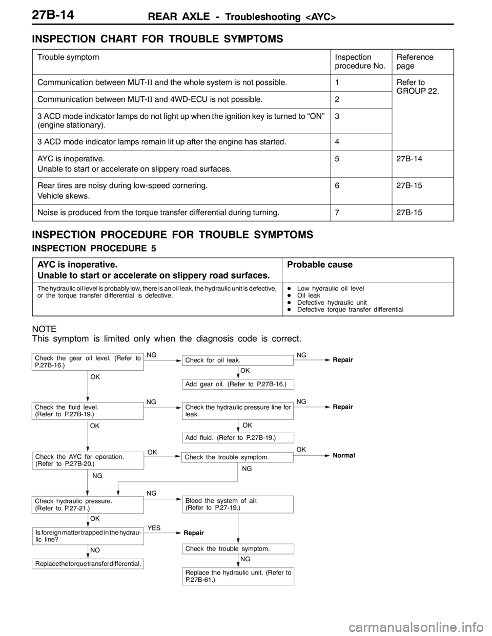
INSPECTION PROCEDURE 5
AYC is inoperative.
Unable to start or accelerate on slippery road surfaces.
Probable cause
The hydraulic oil level is probably low, there is an oil leak, the hydraulic unit is defective,
or the torque transfer differential is defective.DLow hydraulic oil level
DOil leak
DDefective hydraulic unit
DDefective torque transfer differential
NOTE
This symptom is limited only when the diagnosis code is correct.
NG
Replace the hydraulic unit. (Refer to
P.27B-61.)
NG
Add fluid. (Refer to P.27B-19.)
OKRepair
Check the trouble symptom.NO
Replace the torque transfer differential.
OK
Is foreign matter trapped in the hydrau-
lic line?YES
Repair
OK
Check the fluid level.
(Refer to P.27B-19.)Check the hydraulic pressure line for
leak.
OK
Add gear oil. (Refer to P.27B-16.)
OK
Check hydraulic pressure.
(Refer to P.27-21.)NGBleed the system of air.
(Refer to P.27-19.)
Check the gear oil level. (Refer to
P.27B-16.)NGCheck for oil leak.NG
Repair
Check the AYC for operation.
(Refer to P.27B-20.)Check the trouble symptom. OKOK
NGNormal
NGNG
Page 970 of 1449

REAR AXLE -On-vehicle Service27B-24
Torque transfer mechanism part
1. Remove the drive shaft. (Refer to P. 27B-29.)
2. Remove the oil seal from the differential carrier.
3. Using the special tool, drive a new oil seal all the way
into position.
4. Coat the oil seal lips and the drive shaft surface in contact
with the oil seal with the specified grease.
Specified grease: Vaseline
5. Replace the drive shaft circlip with a new one and mount
the drive shaft to the differential carrier. (Refer to P.
27B-29.)
6. Check for correct wheel alignment. (Refer to GROUP
34 – On-vehicle Service.)
ACTION WHEN BATTERY RUNS OUT
When the engine is started using a booster cable where the
battery has completely run down and you attempt to start
the vehicle without waiting for the battery to recover a certain
charge, the engine can misfire and you just cannot start to
move it. In such cases, charge the battery sufficiently; or,
remove the AYC battery cable from the battery fuse assembly
to make AYC inactive before attempting to start the vehicles.
When the battery cable is removed, the ACD mode indicator
lamp lights up. After the battery has been recharged, fit the
battery cable back again and start the engine to ensure that
the ACD mode indicator lamp is off.
MD998829
MD998813 MD998812
Battery fuse assembly
Battery cable
for AYC
Page 1050 of 1449

BASIC BRAKE SYSTEM -On-vehicle Service35A-8
2. If the brake pedal play is not within the standard value,
check the following, and adjust or replace if necessary:
DExcessive play between the brake pedal and the clevis
pin, or between the clevis pin and the brake booster
operating rod
DBrake pedal height
DInstallation position of the stop lamp switch, etc.
CLEARANCE BETWEEN BRAKE PEDAL AND FLOOR
BOARD
1. Turn up the carpet etc. under the brake pedal.
2. Start the engine, depress the brake pedal with
approximately 500 N of force, and measure the clearance
between the brake pedal and the floorboard.
Standard value (C): 90 mm or more
3. If the clearance is outside the standard value, check for
air trapped in the brake line and thickness of the disc
brake pad and dragging in the parking brake.
Adjust and replace defective parts as required.
4. Return the carpet, etc.
BRAKE BOOSTER OPERATING TEST
For simple checking of the brake booster operation, carry
out the following tests:
1. Run the engine for one or two minutes, and then stop
it.
If the pedal depresses fully the first time but gradually
becomes higher when depressed succeeding times, the
booster is operating properly. If the pedal height remains
unchanged, the booster is defective.
2. With the engine stopped, step on the brake pedal several
times.
Then start the engine while the brake pedal is stepped
on.
If the pedal moves downward slightly, the booster is in
good condition. If there is no change, the booster is
defective.
3. With the engine running, step on the brake pedal and
then stop the engine.
Hold the pedal depressed for 30 seconds. If the pedal
height does not change, the booster is in good condition.
If the pedal rises, the booster is defective.
If the above three tests are okay, the booster performance
can be determined as good.
If one of the above three tests is not okay at least, the check
valve, vacuum hose, or booster will be defective.
C
Good No good
When engine is
stoppedWhen engine is
started
GoodNo good