2007 MITSUBISHI LANCER EVOLUTION light
[x] Cancel search: lightPage 1390 of 1449

SWS -Troubleshooting54B-26
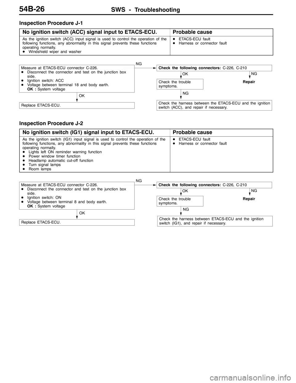
Inspection Procedure J-1
No ignition switch (ACC) signal input to ETACS-ECU.
Probable cause
As the ignition switch (ACC) input signal is used to control the operation of the
following functions, any abnormality in this signal prevents these functions
operating normally.
DWindshield wiper and washerDETACS-ECU fault
DHarness or connector fault
NG
Repair
NG
Check the harness between the ETACS-ECU and the ignition
switch (ACC), and repair if necessary.
OK
Replace ETACS-ECU.
OK
Check the trouble
symptoms.
Measure at ETACS-ECU connector C-226.
DDisconnect the connector and test on the junction box
side.
DIgnition switch: ACC
DVoltage between terminal 18 and body earth.
OK :System voltageNGCheck the following connectors:C-226, C-210
Inspection Procedure J-2
No ignition switch (IG1) signal input to ETACS-ECU.
Probable cause
As the ignition switch (IG1) input signal is used to control the operation of the
following functions, any abnormality in this signal prevents these functions
operating normally.
DLights left ON reminder warning function
DPower window timer function
DHeadlamp automatic cut-off function
DTurn signal lamps
DRoom lampsDETACS-ECU fault
DHarness or connector fault
NG
Repair
NG
Check the harness between ETACS-ECU and the ignition
switch (IG1), and repair if necessary.
OK
Replace ETACS-ECU.
OK
Check the trouble
symptoms.
Measure at ETACS-ECU connector C-226.
DDisconnect the connector and test on the junction box
side.
DIgnition switch: ON
DVoltage between terminal 8 and body earth.
OK :System voltageNGCheck the following connectors:C-226, C-210
Page 1393 of 1449

SWS -Troubleshooting54B-29
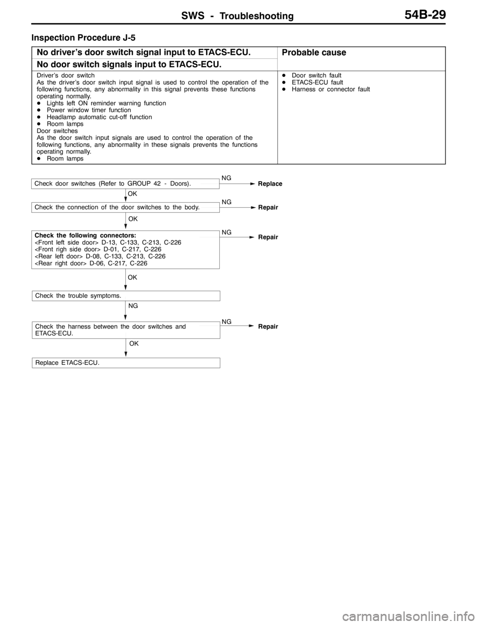
Inspection Procedure J-5
No driver’s door switch signal input to ETACS-ECU.
Probable cause
No door switch signals input to ETACS-ECU.
Driver’s door switch
As the driver’s door switch input signal is used to control the operation of the
following functions, any abnormality in this signal prevents these functions
operating normally.
DLights left ON reminder warning function
DPower window timer function
DHeadlamp automatic cut-off function
DRoom lamps
Door switches
As the door switch input signals are used to control the operation of the
following functions, any abnormality in these signals prevents the functions
operating normally.
DRoom lampsDDoor switch fault
DETACS-ECU fault
DHarness or connector fault
OK
Replace ETACS-ECU.
NG
Check the harness between the door switches and
ETACS-ECU.NG
Repair
OK
Check the trouble symptoms.
OK
Check the following connectors:
Repair
OK
Check the connection of the door switches to the body.NG
Repair
Check door switches (Refer to GROUP 42 - Doors).NG
Replace
Page 1395 of 1449

SWS -Troubleshooting54B-31
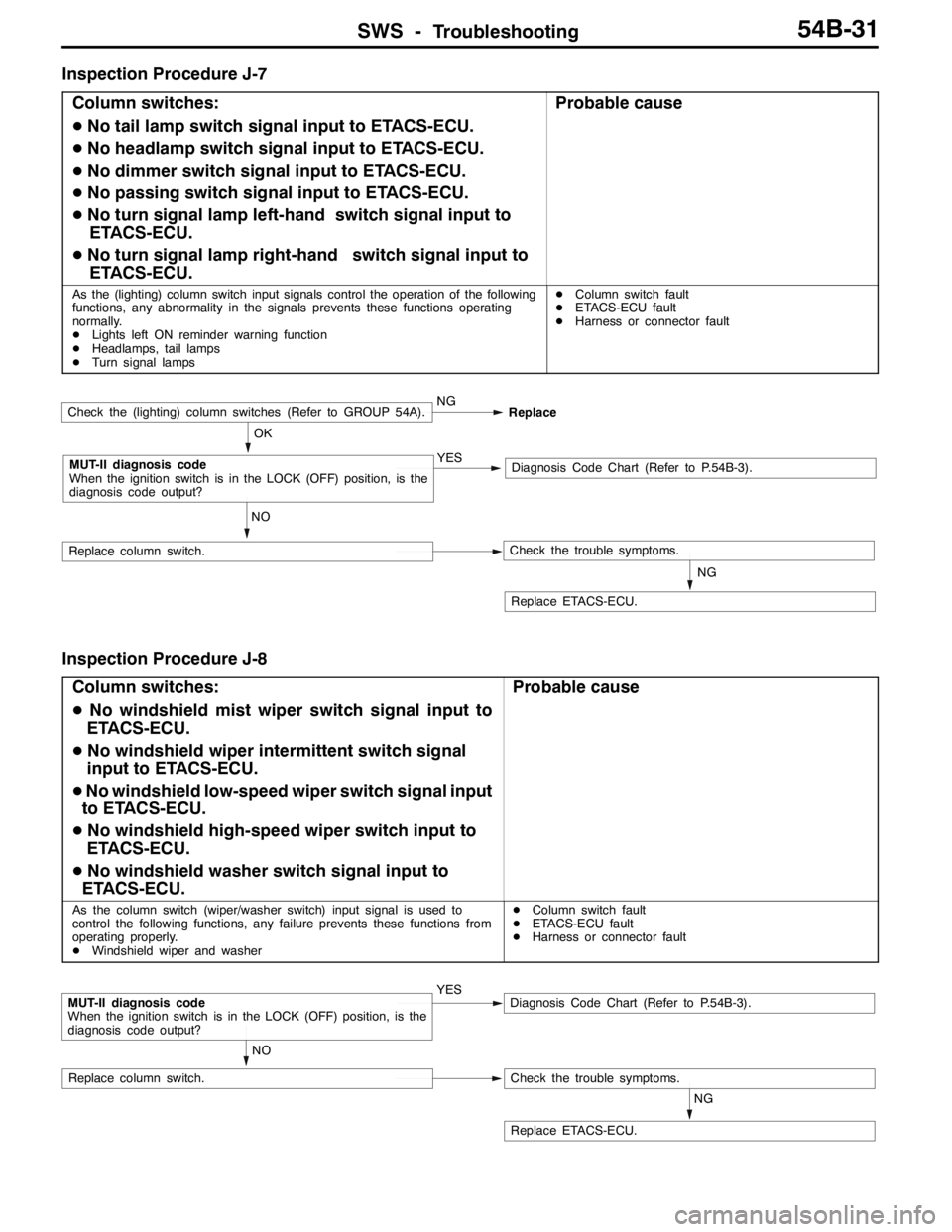
Inspection Procedure J-7
Column switches:
DNo tail lamp switch signal input to ETACS-ECU.
DNo headlamp switch signal input to ETACS-ECU.
DNo dimmer switch signal input to ETACS-ECU.
DNo passing switch signal input to ETACS-ECU.
DNo turn signal lamp left-hand switch signal input to
ETACS-ECU.
DNo turn signal lamp right-hand switch signal input to
ETACS-ECU.
Probable cause
As the (lighting) column switch input signals control the operation of the following
functions, any abnormality in the signals prevents these functions operating
normally.
DLights left ON reminder warning function
DHeadlamps, tail lamps
DTurn signal lampsDColumn switch fault
DETACS-ECU fault
DHarness or connector fault
NG
Replace ETACS-ECU.
NO
Replace column switch.Check the trouble symptoms.
OK
MUT-II diagnosis code
When the ignition switch is in the LOCK (OFF) position, is the
diagnosis code output?YESDiagnosis Code Chart (Refer to P.54B-3).
Check the (lighting) column switches (Refer to GROUP 54A).NG
Replace
Inspection Procedure J-8
Column switches:
DNo windshield mist wiper switch signal input to
ETACS-ECU.
DNo windshield wiper intermittent switch signal
input to ETACS-ECU.
DNo windshield low-speed wiper switch signal input
to ETACS-ECU.
DNo windshield high-speed wiper switch input to
ETACS-ECU.
DNo windshield washer switch signal input to
ETACS-ECU.
Probable cause
As the column switch (wiper/washer switch) input signal is used to
control the following functions, any failure prevents these functions from
operating properly.
DWindshield wiper and washerDColumn switch fault
DETACS-ECU fault
DHarness or connector fault
NG
Replace ETACS-ECU.
NO
Replace column switch.Check the trouble symptoms.
MUT-II diagnosis code
When the ignition switch is in the LOCK (OFF) position, is the
diagnosis code output?YESDiagnosis Code Chart (Refer to P.54B-3).
Page 1397 of 1449

SWS -Troubleshooting54B-33
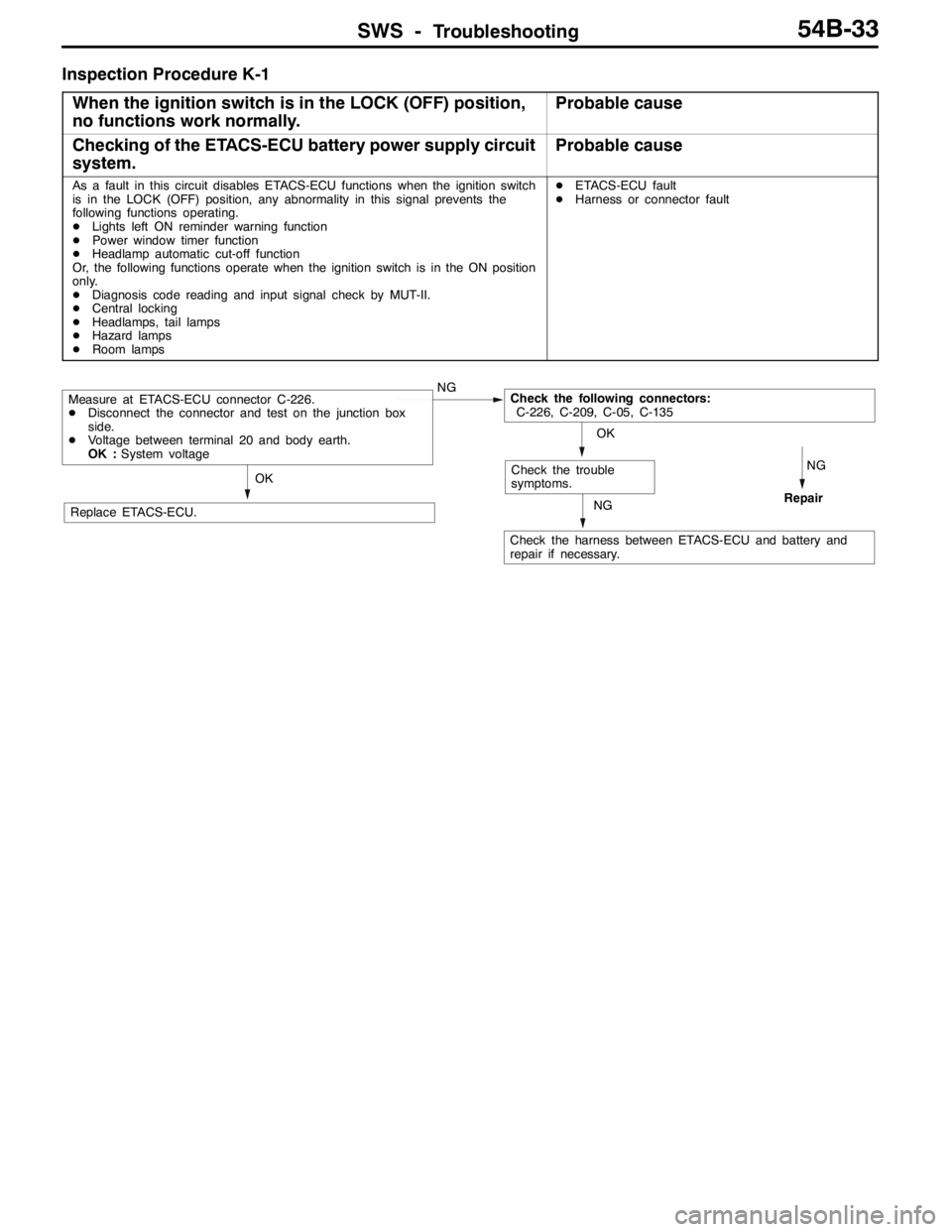
Inspection Procedure K-1
When the ignition switch is in the LOCK (OFF) position,
no functions work normally.
Probable cause
Checking of the ETACS-ECU battery power supply circuit
system.Probable cause
As a fault in this circuit disables ETACS-ECU functions when the ignition switch
is in the LOCK (OFF) position, any abnormality in this signal prevents the
following functions operating.
DLights left ON reminder warning function
DPower window timer function
DHeadlamp automatic cut-off function
Or, the following functions operate when the ignition switch is in the ON position
only.
DDiagnosis code reading and input signal check by MUT-II.
DCentral locking
DHeadlamps, tail lamps
DHazard lamps
DRoom lampsDETACS-ECU fault
DHarness or connector fault
NG
RepairNG
Check the harness between ETACS-ECU and battery and
repair if necessary.
OK
Replace ETACS-ECU.
OK
Check the trouble
symptoms.
Measure at ETACS-ECU connector C-226.
DDisconnect the connector and test on the junction box
side.
DVoltage between terminal 20 and body earth.
OK :System voltageNGCheck the following connectors:
C-226, C-209, C-05, C-135
Page 1404 of 1449

ServiceSpecifications/Lubricants/
Special ToolsHEATER, AIR CONDITIONER AND VENTILATION-55-2
SERVICE SPECIFICATIONS
ItemStandard value
Idlid()NP85050Idlingspeed(rpm):NorPrange850±50Idlingspeed(rpm):NorPrange850±50Idlingspeed(rpm):NorPrange850�r50
Idle-up speed (rpm): N or P range850±50
Register resistance (for blower motor)ΩHI - LO (between terminals 1 and 3)2.54g()
HI - ML (between terminals 1 and 6)1.24
HI - MH (between terminals 1 and 4)0.6
Air conditioner compressor air gap mm0.3 – 0.5
Refrigerant temperature switch operating temperature (_C)ContinuitySlightly below 150gppgp()
No continuity150 or higher (until tempera-
ture falls to 120 when OFF)
NOTE* : When disconnected the compressor connector at A/C ON
LUBRICANTS
ItemsSpecified lubricantsQuantity
Compressor oil mLSUN PAG 56130±10
Pipe couplingSUN PAG 56As required
Refrigerant (g)R134a (HFC-134a)550±20
SPECIAL TOOLS
ToolNumberNameUse
MB991367Special spannerFor use on the air conditioner compressor
armature locknut
MB991386Pin
MB991529Diagnosis code
check harnessFor inspecting the air conditioner using a
voltmeter
Page 1414 of 1449

HEATER, AIR CONDITIONER AND VENTILATION-TroubleshootingHEATER, AIR CONDITIONER AND VENTILATION-Troubleshooting55-12
CHECK AT THE ENGINE-ECU TERMINAL
Terminal no.Check itemCheck whenNormal state
21Fan controller outputRadiator fan: ON0 - 0.3 Vp
Radiator fan: OFF0.7 V or more
22A/C compressor outputA/C compressor relay: OFF0Vpp
A/C compressor relay: ONBattery voltage
or temporarily
6V or more→
1V or less
24A/C-ECU input (A/C2)At A/C low loadBattery voltage
32Condenser fan motor relay (HI)Fan: OFF(engine coolant temperature:90_C
or lower)Battery voltage
Fan: ON(engine coolant tempera-
ture:105_C or lower)1V or more
34Condenser fan motor relay (LOW)Fan: OFF(engine coolant temperature:90_C
or lower)Battery voltage
Fan: ON(engine coolant tempera-
ture:105_C or lower)1V or more
45A/C-ECU input (A/C1)A/C ON (When dual pressure switch is ON)Battery voltage
CHECK AT THE A/C-ECU TERMINAL
Termi-
nal no.Check itemCheck whenNormal state
1Rear defogger switchDefogger switch: ON0Vgg
Defogger switch: OFFBattery voltage
2Inside/outside air changeover
dt(tidi)
When damper moved to inside circulation position0Vg
damper motor (outside air)When damper moved to outside air induction
positionBattery voltage
3Inside/outside air changeover
dt(i idi)
When damper moved to inside circulation positionBattery voltageg
damper motor (inside air)When damper moved to outside air induction
position0V
4Engine-ECU output (A/C1)When A/C OFF0Vgp()
A/C switch: ON, blower: ON (room temperature)Battery voltage
5Engine-ECU output (A/C2)At A/C low loadBattery voltagegp()
At A/C high load0V
6Illumination power supplyLighting switches: ONBattery voltage
7---
8Blower switch (LO)Blower switch: LOBattery voltage
Page 1415 of 1449

HEATER, AIR CONDITIONER AND VENTILATION-Troubleshooting55-13
Termi-
nal no.Normal state Check when Check item
9---
10Ignition switch (IG2) power supplyIgnition switch: ONBattery voltage
11Illumination earthAny time0V
12EarthAny time0V
13Air thermo sensorWhen temperature around sensor 25_C (1.5kΩ)2.2 V
14---
15---
16Air thermo sensor earthAny time0V
CHECK AT THE A/C-ECU TERMINAL
Termi-
nal no.Check itemCheck whenNormal state
1Engine-ECU output (A/C1)When A/C OFF0Vgp()
A/C switch: ON, blower: ON (room temperature)Battery voltage
2Engine-ECU output (A/C2)At A/C low loadBattery voltagegp()
At A/C high load0V
3EarthAny time0V
4Air thermo sensor earthAny time0V
5Illumination power supplyLighting switches: ONBattery voltage
6Air thermo sensorWhen temperature around sensor 25_C (1.5kΩ)2.2 V
7Ignition switch (IG2) power supplyIgnition switch: ONBattery voltage
8Blower switch (LO)Blower switch: LOBattery voltage
9Rear defogger switchDefogger switch: ON0Vgg
Defogger switch: OFFBattery voltage
10Inside/outside air changeover
dt(tidi)
When damper moved to inside circulation position0Vg
damper motor (outside air)When damper moved to outside air induction
positionBattery voltage
11Inside/outside air changeover
dt(i idi)
When damper moved to inside circulation positionBattery voltageg
damper motor (inside air)When damper moved to outside air induction
position0V
12Illumination earthAny time0V
Page 1422 of 1449

HEATER, AIR CONDITIONER AND VENTILATION–On-vehicle Service HEATER, AIR CONDITIONER AND VENTILATION–On-vehicle Service55-20
PERFORMANCE TEST
1. The vehicles to be tested should be in a place that is
not in direct sunlight.
2. Close the high and low-pressure valve of the gauge
manifold.
3. Connect the charging hose (blue) to the low-pressure
valve and connect the charging hose (red) to the
high-pressure valve of the gauge manifold.
4. Install the quick joint (for low-pressure) to the charging
hose (blue), and connect the quick joint (for high-pressure)
to the charging hose (red).
5. Connect the quick joint (for low-pressure) to the
low-pressure service valve and connect the quick joint
(for high-pressure) to the high-pressure service valve.
NOTE
The high-pressure service valve is on liquid pipe A and the
low-pressure service valve is on the suction hose.
Caution
To connect the quick joint, press section “A” firmly
against the service valve until a click is heard.
When connecting, run your hand along the hose while
pressing to ensure that there are no bends in the
hose.
6. Start the engine.
7. Set the controls to the A/C as follows:
DA/C switch: A/C - ON position
DMode selection: Face position
DTemperature control: Max. cooling position
DAir selection: Recirculation position
DBlower switch: HI (Fast) position
8. Keep engine speed to idling speed with A/C clutch engaged.
9. Engine should be warmed up with doors and all windows
opened.
10. Insert a thermometer in the center A/C outlet and operate
the engine for 20 minutes.
11. Note the discharge air temperature.
NOTE
If the clutch cycles, take the reading before the clutch
disengages.
Performance Temperature Chart
Garage ambient temperature_C20253035
Discharge air temperature_C8-1112 - 1617 - 2122.5 - 27.5
Compressor high-pressure kPa740 - 840950 - 1,0501,160 - 1,3001,360 - 1,550
Compressor low-pressure kPa150 - 190190 - 240240 - 300300 - 375
Low-pressure valve
High-pressure valve
Gauge manifold
Charging
hose (red)
Charging
hose (blue)
Adaptor
valve (for low
pressure)Sleeve
Adaptor valve
(for high pressure)
Low-
pressure
service
valveHigh-
pressure
service
valveA
Thermometer