Page 1228 of 1449
INTERIOR -Front Floor Console52A-10
FRONT FLOOR CONSOLE
REMOVAL AND INSTALLATION
Pre-removal and Post-installation Operation
Removal and Installation of Rear Foor Console
(Refer to P.52A - 12.)
6
4
7 13
2 8 5
1
11 <
L.H. DRIVE VEHICLE>
9
10
12
Removal steps
1. Console side cover
2. Shift lever knob
3. Front floor console assembly
4. Front floor console panel
5. Cigarette lighter
6. Ashtray7. Shift lever cover
8. Shift lever panel garnish
9. Front floor console
10. Harness
11. Console side cover bracket
12. Front floor console bracket
Page 1229 of 1449
INTERIOR -Front Floor Console52A-11
REMOVAL AND INSTALLATION
Pre-removal and Post-installation Operation
Removal and Installation of Rear Floor Console
(Refer to P.52A-12.)
3
456
78
9
12
1012 11
Removal steps
1. Console side cover
2. Shift lever knob
3. Front floor console assembly
4. Front floor console panel
5. Cigarette lighter
6. Ashtray7. Shift lever cover
8. Shift lever panel garnish
9. Front floor console
10. Harness
11. Console side cover bracket
12. Front floor console bracket
Page 1302 of 1449
SRS - Air Bag Modules and Clock Spring52B-58
"CASTEERING WHEEL/STEERING WHEEL - AIR BAG
MODULE ASSEMBLY INSTALLATION
1. After checking that centering of the clock spring has been
done, install the steering wheel or the steering wheel - air
bag module assembly.
Caution
Do not engage the harness of the clock spring when
installing the steering wheel or the steering wheel - air
bag module assembly.
2. After installation, check that no abnormalities occur when
the steering wheel is fully turned to the left or the right.
"DAPOST-INSTALLATION INSPECTION
1. Check that no abnormal noise or improper operation can
be caused by rotating the steering wheel in left and right
directions slightly.
(driver’s air bag module, clock spring)
2. Turn the ignition switch to the ON position.
3. Check that the SRS warning lamp illuminates for 6 to
8 seconds and goes out.
4. Carry out troubleshooting if the lamp does not go out.
(Refer to P.52-6.)
SRS warning lamp
Page 1323 of 1449

54A-3
SIDE TURN-SIGNAL LAMP 31............
SPECIAL TOOL 31............................
SIDE TURN-SIGNAL LAMP 31..................
ROOM LAMP 31.........................
TROUBLESHOOTING 31.......................
REAR COMBINATION LAMP 32...........
SPECIAL TOOL 32............................
TROUBLESHOOTING 32.......................
REAR COMBINATION LAMP 32................
HIGH-MOUNTED STOP LAMP 34.........
ON-VEHICLE SERVICE 34......................
High-mounted Stop Lamp Bulb Replacement 34.
HIGH-MOUNTED STOP LAMP 34................
LICENCE PLATE LAMP 35...............
ON-VEHICLE SERVICE 35.....................
License Plate Lamp Replacement 35...........
LICENCE PLATE LAMP 35.....................
HAZARD WARNING LAMP SWITCH 36....
SPECIAL TOOL 36............................
HAZARD WARNING LAMP SWITCH 36.........
HORN 37................................
CIGARETTE LIGHTER 37.................
COLUMN SWITCH 38....................
SPECIAL TOOL 38............................
COLUMN SWITCH 38..........................
CLOCK 40...............................
SPECIAL TOOL 40............................
CLOCK 40....................................
POLE ANTENNA 41......................
ROOF ANTENNA 42......................
DEFOGGER 42...........................
TROUBLESHOOTING 42......................
ON-VEHICLE SERVICE 43.....................
Printed Heater Check 43......................
Defogger Relay Continuity Check 43...........
DEFOGGER SWITCH 43.......................
Page 1348 of 1449

CHASSIS ELECTRICAL -Headlamp Assembly54A-28
HEADLAMP INTENSITY MEASUREMENT
1. Using a photometer, and following its manufacture’s
instruction manual.
2. Maintain an engine speed of 2,000 r/min., with the battery
in the charging condition
3. Set the headlamps to high beam
4. Measure the headlamp centre intensity (a point of H line
and V line) and check to be sure that the limit value
is satisfied.
Limit:
High beam 30,000 cd or more per one headlamp
NOTE
1. There may be special local regulations pertaining to
headlamp intensity, be sure to make any adjustments
necessary to satisfy such regulations.
2. If an illuminometer is used to make the measurements,
convert its values to photometer values by using the
following formula.
I=Er
2Where:
I=intensity (cd)
E=illumination (lux)
r=distance (m) from headlamps to illuminometer
Caution
1. On the headlamp not yet adjusted, perform aiming
with connector removed and the lamps switched off,
if applicable. In addition, care should be taken to
prevent a change of optical axis when connector is
reconnected.
2. Plastic outer lens are equipped with headlamps. When
lens surface is covered with materials for not
penetrating light, headlamp operation time should be
within 3 minutes. In addition, masking such as taping
should not be performed.
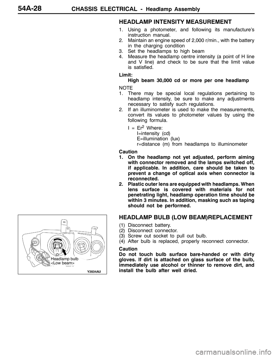
HEADLAMP BULB (LOW BEAM)REPLACEMENT
(1) Disconnect battery.
(2) Disconnect connector.
(3) Screw out socket to pull out bulb.
(4) After bulb is replaced, properly reconnect connector.
Caution
Do not touch bulb surface bare-handed or with dirty
gloves. If dirt is attached on glass surface of the bulb,
immediately use alcohol or thinner to remove dirt, and
install the bulb after well dried.
Headlamp bulb
Page 1349 of 1449

CHASSIS ELECTRICAL -Headlamp AssemblyCHASSIS ELECTRICAL -Headlamp AssemblyCHASSIS ELECTRICAL -Headlamp Assembly54A-29
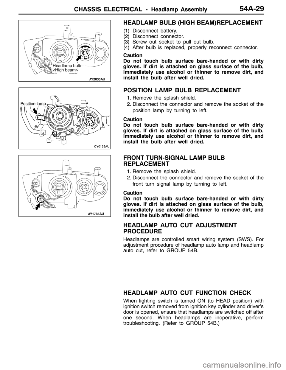
HEADLAMP BULB (HIGH BEAM)REPLACEMENT
(1) Disconnect battery.
(2) Disconnect connector.
(3) Screw out socket to pull out bulb.
(4) After bulb is replaced, properly reconnect connector.
Caution
Do not touch bulb surface bare-handed or with dirty
gloves. If dirt is attached on glass surface of the bulb,
immediately use alcohol or thinner to remove dirt, and
install the bulb after well dried.
POSITION LAMP BULB REPLACEMENT
1. Remove the splash shield.
2. Disconnect the connector and remove the socket of the
position lamp by turning to left.
Caution
Do not touch bulb surface bare-handed or with dirty
gloves. If dirt is attached on glass surface of the bulb,
immediately use alcohol or thinner to remove dirt, and
install the bulb after well dried.
FRONT TURN-SIGNAL LAMP BULB
REPLACEMENT
1. Remove the splash shield.
2. Disconnect the connector and remove the socket of the
front turn signal lamp by turning to left.
Caution
Do not touch bulb surface bare-handed or with dirty
gloves. If dirt is attached on glass surface of the bulb,
immediately use alcohol or thinner to remove dirt, and
install the bulb after well dried.
HEADLAMP AUTO CUT ADJUSTMENT
PROCEDURE
Headlamps are controlled smart wiring system (SWS). For
adjustment procedure of headlamp auto lamp and headlamp
auto cut, refer to GROUP 54B.
HEADLAMP AUTO CUT FUNCTION CHECK
When lighting switch is turned ON (to HEAD position) with
ignition switch removed from ignition key cylinder and driver’s
door is opened, ensure that headlamps are switched off after
one second. When headlamps are inoperative, perform
troubleshooting. (Refer to GROUP 54B.)
Headlamp bulb
Position lamp
Page 1357 of 1449
CHASSIS ELECTRICAL-Hazard Warning Lamp Switch/Horn/Cigarette Lighter
ILL
ILL
54A-37
INSPECTION
HAZARD WARNING LAMP SWITCH CONTINUITY
CHECK
Switch PositionTerminal No.
1234
OFF
ON
HORN
INSPECTION
HORN RELAY CONTINUITY CHECK
Switch PositionTerminal No.
1432
De-energized
Energized
CIGARETTE LIGHTER
INSPECTION
DRemove plug and check for wear on spot.
DCheck for residual cigarette or foreign object on element.
DWith circuit tester, check for element continuity.
Horn relay
Spot
Element
Page 1358 of 1449
CHASSIS ELECTRICAL-Column Switch54A-38
COLUMN SWITCH
SPECIAL TOOL
ToolNumberNameUse
MB990784Ornament removerColumn cover removal
COLUMN SWITCH
REMOVAL AND INSTALLATION
2
1
Section A - A
1 34A
A
Pawls
2
A
A
A
A
A
A
Removal steps
1. Lower column cover
2. Upper column cover
3. Lighting switch
4. Wiper/Washer switch