2006 TOYOTA RAV4 warning
[x] Cancel search: warningPage 1689 of 2000
RS–40SUPPLEMENTAL RESTRAINT SYSTEM – AIRBAG SYSTEM
RS
3. SYMPTOM SIMULATION
HINT:
The most difficult case in troubleshooting is when no
problem symptoms occur. In such a case, a through
problem analysis must be carried out. A simulation of the
same or similar conditions and environment in which the
problem occurred in the customer's vehicle should be
carried out. No matter how much skill or experience a
technician has, troubleshooting without confirming the
problem symptoms will lead to important repairs being
overlooked and mistakes or delays.
This leads to a standstill in troubleshooting.
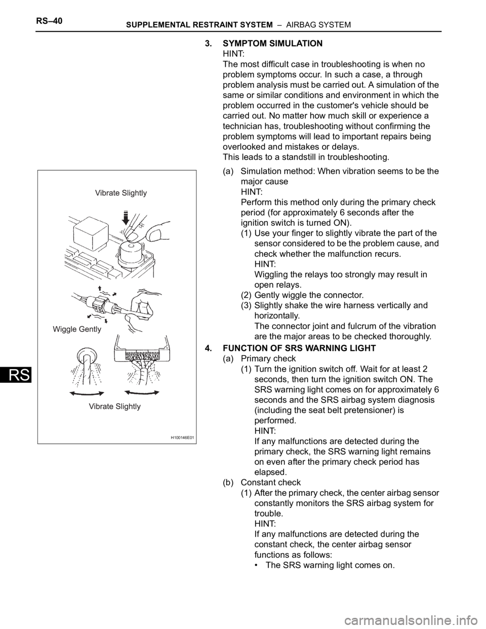
(a) Simulation method: When vibration seems to be the
major cause
HINT:
Perform this method only during the primary check
period (for approximately 6 seconds after the
ignition switch is turned ON).
(1) Use your finger to slightly vibrate the part of the
sensor considered to be the problem cause, and
check whether the malfunction recurs.
HINT:
Wiggling the relays too strongly may result in
open relays.
(2) Gently wiggle the connector.
(3) Slightly shake the wire harness vertically and
horizontally.
The connector joint and fulcrum of the vibration
are the major areas to be checked thoroughly.
4. FUNCTION OF SRS WARNING LIGHT
(a) Primary check
(1) Turn the ignition switch off. Wait for at least 2
seconds, then turn the ignition switch ON. The
SRS warning light comes on for approximately 6
seconds and the SRS airbag system diagnosis
(including the seat belt pretensioner) is
performed.
HINT:
If any malfunctions are detected during the
primary check, the SRS warning light remains
on even after the primary check period has
elapsed.
(b) Constant check
(1) After the primary check, the center airbag sensor
constantly monitors the SRS airbag system for
trouble.
HINT:
If any malfunctions are detected during the
constant check, the center airbag sensor
functions as follows:
• The SRS warning light comes on.
H100146E01
Page 1690 of 2000
SUPPLEMENTAL RESTRAINT SYSTEM – AIRBAG SYSTEMRS–41
RS
• The SRS warning light goes off, and then
comes on again. This blinking pattern
indicates a source voltage drop. The SRS
warning light goes off 10 seconds after the
source voltage returns to normal.
(c) Review
(1) When the airbag system is normal:
The SRS warning light comes on only during the
primary check period (for approximately 6
seconds after the ignition switch is turned ON).
(2) When the airbag system malfunctions:
• The SRS warning light blinks after the
primary check period has elapsed.
• The SRS warning light goes off after the
primary check, but comes on again during the
constant check.
• The SRS warning light remains off even after
the ignition switch is turned from LOCK to
ON. However, if malfunctions such as an
open circuit have occurred in the wire
harness between the meter and ECU, the
warning light comes on 10 seconds after the
ignition switch is turned ON.
HINT:
The center airbag sensor keeps the SRS
warning light on if any malfunctions have been
detected in the airbag system.
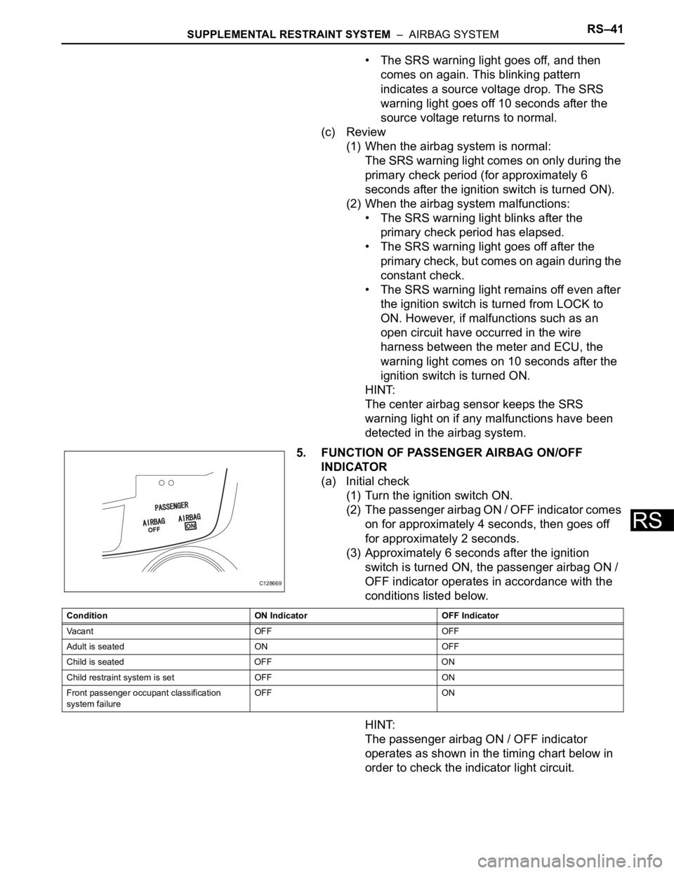
5. FUNCTION OF PASSENGER AIRBAG ON/OFF
INDICATOR
(a) Initial check
(1) Turn the ignition switch ON.
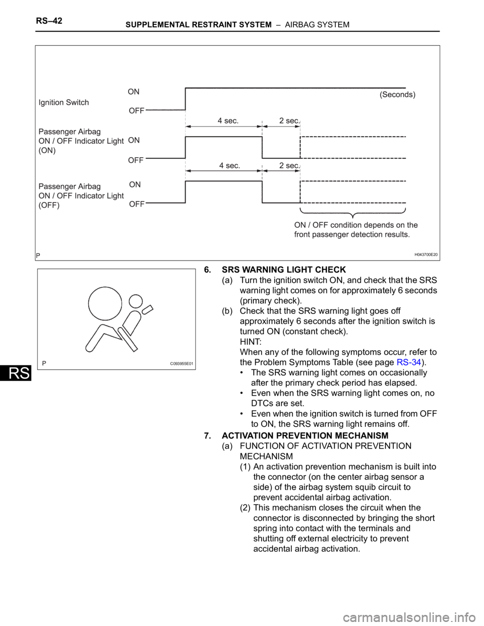
(2) The passenger airbag ON / OFF indicator comes
on for approximately 4 seconds, then goes off
for approximately 2 seconds.
(3) Approximately 6 seconds after the ignition
switch is turned ON, the passenger airbag ON /
OFF indicator operates in accordance with the
conditions listed below.
HINT:
The passenger airbag ON / OFF indicator
operates as shown in the timing chart below in
order to check the indicator light circuit.
C128669
Condition ON Indicator OFF Indicator
Va c a n t O F F O F F
Adult is seated ON OFF
Child is seated OFF ON
Child restraint system is set OFF ON
Front passenger occupant classification
system failureOFF ON
Page 1691 of 2000
RS–42SUPPLEMENTAL RESTRAINT SYSTEM – AIRBAG SYSTEM
RS
6. SRS WARNING LIGHT CHECK
(a) Turn the ignition switch ON, and check that the SRS
warning light comes on for approximately 6 seconds
(primary check).
(b) Check that the SRS warning light goes off
approximately 6 seconds after the ignition switch is
turned ON (constant check).
HINT:
When any of the following symptoms occur, refer to
the Problem Symptoms Table (see page RS-34).
• The SRS warning light comes on occasionally
after the primary check period has elapsed.
• Even when the SRS warning light comes on, no
DTCs are set.
• Even when the ignition switch is turned from OFF
to ON, the SRS warning light remains off.
7. ACTIVATION PREVENTION MECHANISM
(a) FUNCTION OF ACTIVATION PREVENTION
MECHANISM
(1) An activation prevention mechanism is built into
the connector (on the center airbag sensor a
side) of the airbag system squib circuit to
prevent accidental airbag activation.
(2) This mechanism closes the circuit when the
connector is disconnected by bringing the short
spring into contact with the terminals and
shutting off external electricity to prevent
accidental airbag activation.
H043700E20
C093955E01
Page 1700 of 2000
SUPPLEMENTAL RESTRAINT SYSTEM – AIRBAG SYSTEMRS–51
RS
(c) Read the DTCs.
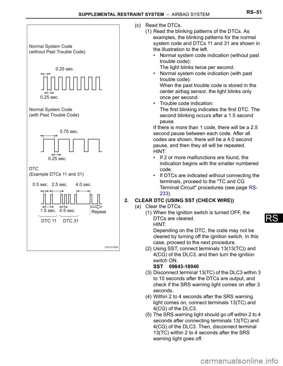
(1) Read the blinking patterns of the DTCs. As
examples, the blinking patterns for the normal
system code and DTCs 11 and 31 are shown in
the illustration to the left.
• Normal system code indication (without past
trouble code):
The light blinks twice per second.
• Normal system code indication (with past
trouble code):
When the past trouble code is stored in the
center airbag sensor, the light blinks only
once per second.
• Trouble code indication:
The first blinking indicates the first DTC. The
second blinking occurs after a 1.5 second
pause.
If there is more than 1 code, there will be a 2.5
second pause between each code. After all
codes are shown, there will be a 4.0 second
pause, and then they all will be repeated.
HINT:
• If 2 or more malfunctions are found, the
indication begins with the smaller numbered
code.
• If DTCs are indicated without connecting the
terminals, proceed to the "TC and CG
Terminal Circuit" procedures (see page RS-
233).
2. CLEAR DTC (USING SST (CHECK WIRE))
(a) Clear the DTCs.
(1) When the ignition switch is turned OFF, the
DTCs are cleared.
HINT:
Depending on the DTC, the code may not be
cleared by turning off the ignition switch. In this
case, proceed to the next procedure.
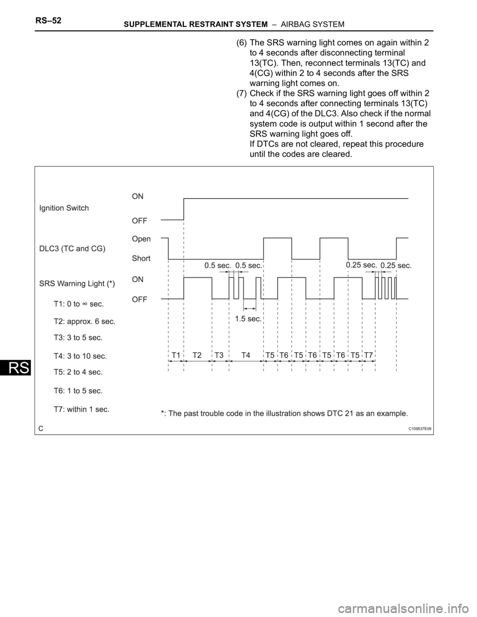
(2) Using SST, connect terminals 13(13(TC)) and
4(CG) of the DLC3, and then turn the ignition
switch ON.
SST 09843-18040
(3) Disconnect terminal 13(TC) of the DLC3 within 3
to 10 seconds after the DTCs are output, and
check if the SRS warning light comes on after 3
seconds.
(4) Within 2 to 4 seconds after the SRS warning
light comes on, connect terminals 13(TC) and
4(CG) of the DLC3.
(5) The SRS warning light should go off within 2 to 4
seconds after connecting terminals 13(TC) and
4(CG) of the DLC3. Then, disconnect terminal
13(TC) within 2 to 4 seconds after the SRS
warning light goes off.
H101311E04
Page 1701 of 2000
RS–52SUPPLEMENTAL RESTRAINT SYSTEM – AIRBAG SYSTEM
RS
(6) The SRS warning light comes on again within 2
to 4 seconds after disconnecting terminal
13(TC). Then, reconnect terminals 13(TC) and
4(CG) within 2 to 4 seconds after the SRS
warning light comes on.
(7) Check if the SRS warning light goes off within 2
to 4 seconds after connecting terminals 13(TC)
and 4(CG) of the DLC3. Also check if the normal
system code is output within 1 second after the
SRS warning light goes off.
If DTCs are not cleared, repeat this procedure
until the codes are cleared.
C109537E09
Page 1704 of 2000
SUPPLEMENTAL RESTRAINT SYSTEM – AIRBAG SYSTEMRS–55
RS
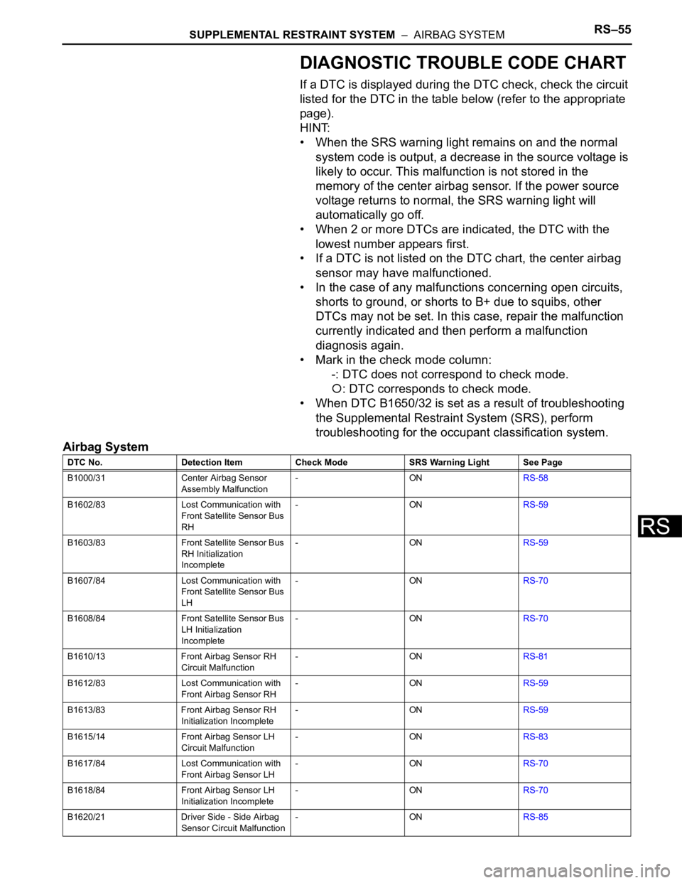
DIAGNOSTIC TROUBLE CODE CHART
If a DTC is displayed during the DTC check, check the circuit
listed for the DTC in the table below (refer to the appropriate
page).
HINT:
• When the SRS warning light remains on and the normal
system code is output, a decrease in the source voltage is
likely to occur. This malfunction is not stored in the
memory of the center airbag sensor. If the power source
voltage returns to normal, the SRS warning light will
automatically go off.
• When 2 or more DTCs are indicated, the DTC with the
lowest number appears first.
• If a DTC is not listed on the DTC chart, the center airbag
sensor may have malfunctioned.
• In the case of any malfunctions concerning open circuits,
shorts to ground, or shorts to B+ due to squibs, other
DTCs may not be set. In this case, repair the malfunction
currently indicated and then perform a malfunction
diagnosis again.
• Mark in the check mode column:
-: DTC does not correspond to check mode.
: DTC corresponds to check mode.
• When DTC B1650/32 is set as a result of troubleshooting
the Supplemental Restraint System (SRS), perform
troubleshooting for the occupant classification system.
Airbag System
DTC No. Detection Item Check Mode SRS Warning Light See Page
B1000/31 Center Airbag Sensor
Assembly Malfunction-ONRS-58
B1602/83 Lost Communication with
Front Satellite Sensor Bus
RH-ONRS-59
B1603/83 Front Satellite Sensor Bus
RH Initialization
Incomplete-ONRS-59
B1607/84 Lost Communication with
Front Satellite Sensor Bus
LH-ONRS-70
B1608/84 Front Satellite Sensor Bus
LH Initialization
Incomplete-ONRS-70
B1610/13 Front Airbag Sensor RH
Circuit Malfunction-ONRS-81
B1612/83 Lost Communication with
Front Airbag Sensor RH-ONRS-59
B1613/83 Front Airbag Sensor RH
Initialization Incomplete-ONRS-59
B1615/14 Front Airbag Sensor LH
Circuit Malfunction-ONRS-83
B1617/84 Lost Communication with
Front Airbag Sensor LH-ONRS-70
B1618/84 Front Airbag Sensor LH
Initialization Incomplete-ONRS-70
B1620/21 Driver Side - Side Airbag
Sensor Circuit Malfunction-ONRS-85
Page 1705 of 2000
RS–56SUPPLEMENTAL RESTRAINT SYSTEM – AIRBAG SYSTEM
RS
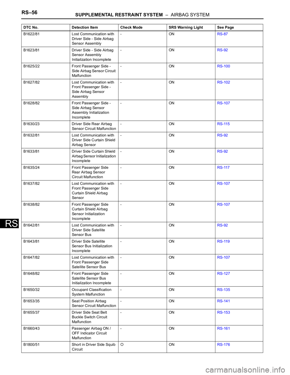
B1622/81 Lost Communication with
Driver Side - Side Airbag
Sensor Assembly-ONRS-87
B1623/81 Driver Side - Side Airbag
Sensor Assembly
Initialization Incomplete-ONRS-92
B1625/22 Front Passenger Side -
Side Airbag Sensor Circuit
Malfunction-ONRS-100
B1627/82 Lost Communication with
Front Passenger Side -
Side Airbag Sensor
Assembly-ONRS-102
B1628/82 Front Passenger Side -
Side Airbag Sensor
Assembly Initialization
Incomplete-ONRS-107
B1630/23 Driver Side Rear Airbag
Sensor Circuit Malfunction-ONRS-115
B1632/81 Lost Communication with
Driver Side Curtain Shield
Airbag Sensor-ONRS-92
B1633/81 Driver Side Curtain Shield
Airbag Sensor Initialization
Incomplete-ONRS-92
B1635/24 Front Passenger Side
Rear Airbag Sensor
Circuit Malfunction-ONRS-117
B1637/82 Lost Communication with
Front Passenger Side
Curtain Shield Airbag
Sensor-ONRS-107
B1638/82 Front Passenger Side
Curtain Shield Airbag
Sensor Initialization
Incomplete-ONRS-107
B1642/81 Lost Communication with
Driver Side Satellite
Sensor Bus-ONRS-92
B1643/81 Driver Side Satellite
Sensor Bus Initialization
Incomplete-ONRS-119
B1647/82 Lost Communication with
Front Passenger Side
Satellite Sensor Bus-ONRS-107
B1648/82 Front Passenger Side
Satellite Sensor Bus
Initialization Incomplete-ONRS-127
B1650/32 Occupant Classification
System Malfunction-ONRS-135
B1653/35 Seat Position Airbag
Sensor Circuit Malfunction-ONRS-141
B1655/37 Driver Side Seat Belt
Buckle Switch Circuit
Malfunction-ONRS-153
B1660/43 Passenger Airbag ON /
OFF Indicator Circuit
Malfunction-ONRS-161
B1800/51 Short in Driver Side Squib
Circuit
ONRS-176 DTC No. Detection Item Check Mode SRS Warning Light See Page
Page 1706 of 2000
SUPPLEMENTAL RESTRAINT SYSTEM – AIRBAG SYSTEMRS–57
RS
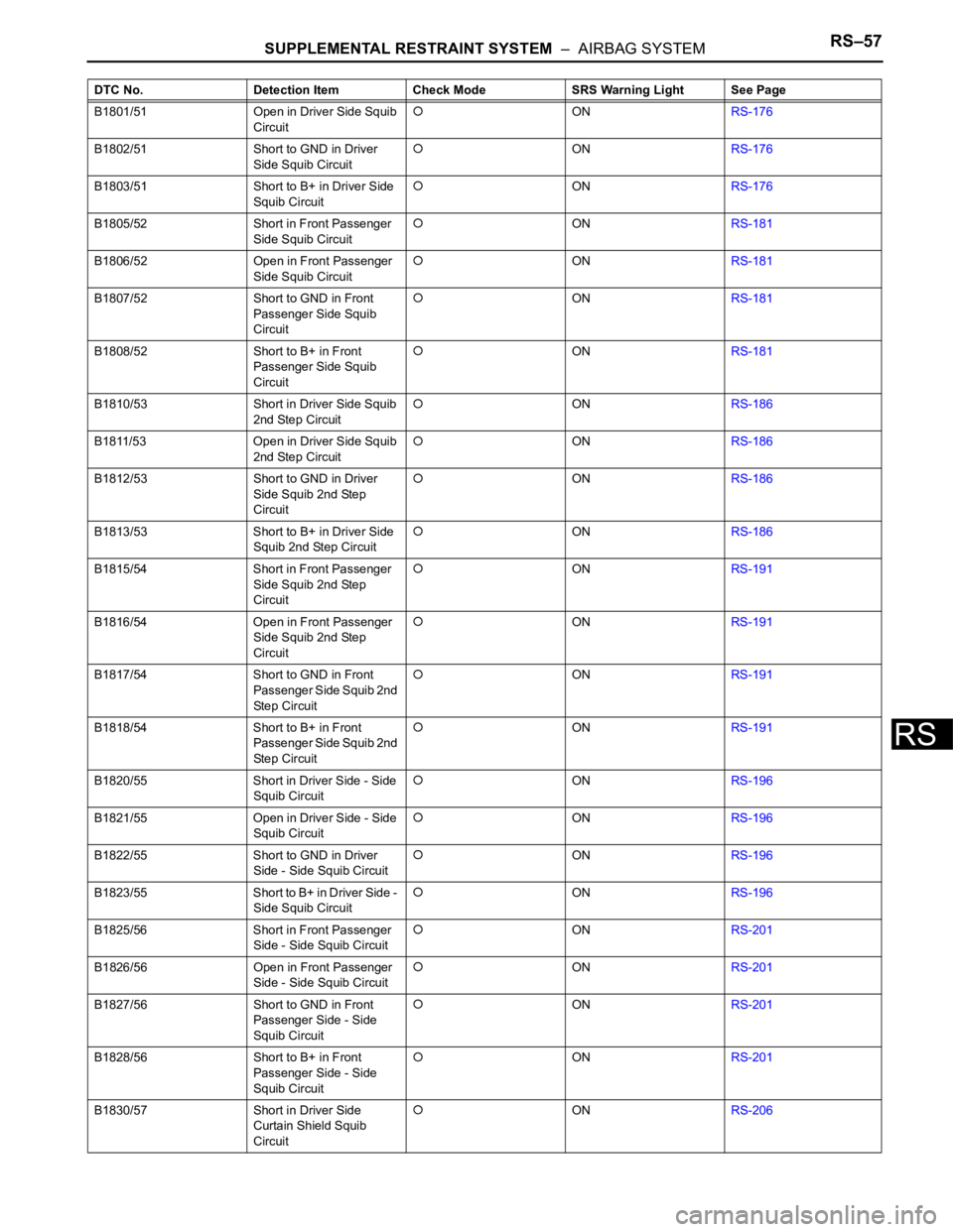
B1801/51 Open in Driver Side Squib
CircuitONRS-176
B1802/51 Short to GND in Driver
Side Squib Circuit
ONRS-176
B1803/51 Short to B+ in Driver Side
Squib Circuit
ONRS-176
B1805/52 Short in Front Passenger
Side Squib Circuit
ONRS-181
B1806/52 Open in Front Passenger
Side Squib Circuit
ONRS-181
B1807/52 Short to GND in Front
Passenger Side Squib
Circuit
ONRS-181
B1808/52 Short to B+ in Front
Passenger Side Squib
Circuit
ONRS-181
B1810/53 Short in Driver Side Squib
2nd Step Circuit
ONRS-186
B1811/53 Open in Driver Side Squib
2nd Step Circuit
ONRS-186
B1812/53 Short to GND in Driver
Side Squib 2nd Step
Circuit
ONRS-186
B1813/53 Short to B+ in Driver Side
Squib 2nd Step Circuit
ONRS-186
B1815/54 Short in Front Passenger
Side Squib 2nd Step
Circuit
ONRS-191
B1816/54 Open in Front Passenger
Side Squib 2nd Step
Circuit
ONRS-191
B1817/54 Short to GND in Front
Passenger Side Squib 2nd
Step Circuit
ONRS-191
B1818/54 Short to B+ in Front
Passenger Side Squib 2nd
Step Circuit
ONRS-191
B1820/55 Short in Driver Side - Side
Squib Circuit
ONRS-196
B1821/55 Open in Driver Side - Side
Squib Circuit
ONRS-196
B1822/55 Short to GND in Driver
Side - Side Squib Circuit
ONRS-196
B1823/55 Short to B+ in Driver Side -
Side Squib Circuit
ONRS-196
B1825/56 Short in Front Passenger
Side - Side Squib Circuit
ONRS-201
B1826/56 Open in Front Passenger
Side - Side Squib Circuit
ONRS-201
B1827/56 Short to GND in Front
Passenger Side - Side
Squib Circuit
ONRS-201
B1828/56 Short to B+ in Front
Passenger Side - Side
Squib Circuit
ONRS-201
B1830/57 Short in Driver Side
Curtain Shield Squib
Circuit
ONRS-206 DTC No. Detection Item Check Mode SRS Warning Light See Page