2006 TOYOTA RAV4 check transmission fluid
[x] Cancel search: check transmission fluidPage 419 of 2000

MA–12MAINTENANCE – CHASSIS
MA
GENERAL MAINTENANCE
(2006/01- )
1. INSPECT STEERING LINKAGE AND GEAR HOUSING
(a) Check the steering wheel free play.
(b) Check the steering linkage for looseness or
damage.
(1) Check that the tie rod ends do not have
excessive play.
(2) Check that the dust seals and boots are not
damaged.
(3) Check that the boot clamps are not loose.
(4) Check that the steering gear housing is not
damaged.
(5) Check that the connectors are properly
connected to the steering gear housing.
2. INSPECT BALL JOINTS AND DUST COVERS
(a) Inspect the ball joints for excessive looseness.
(1) Jack up the front of the vehicle and place
wooden blocks with a height of 180 to 200 mm
(7.09 to 7.87 in.) under the front tires.
(2) Lower the vehicle until the front coil spring has
about half its ordinary load. Place stands under
the vehicle for safety.
(3) Check that the front wheels are pointing
straight ahead. Use wheel chocks on all 4
wheels.
(4) Using a lever, pry up the end of the lower arm.
Check the amount of play.
Maximum ball joint vertical play:
0 mm (0 in.)
If there is any play, replace the ball joint.
(b) Check the dust cover for damage.
3. INSPECT DRIVE SHAFT BOOTS
(a) Check the drive shaft boots for loose clamps,
grease leakage, kinks or damage.
4. INSPECT AUTOMATIC TRANSAXLE FLUID LEVEL
(a) Visually check the transmission for fluid leakage. If
oil is leaking, find the cause and repair it.
5. INSPECT TRANSFER OIL (for 4WD)
(a) Visually check the transfer for oil leakage. If oil is
leaking, find the cause and repair it.
6. INSPECT REAR DIFFERENTIAL OIL (for 4WD)
(a) For the rear differential oil inspection, refer to the
following procedures (see page DF-3).
Type See procedures
U151E See page AX-126
U151F See page AX-126
Type See procedures
Front Oil See page TF-45
Rear Oil See page TF-45
Page 687 of 2000

2GR-FE ENGINE MECHANICAL – ENGINE ASSEMBLYEM–41
EM
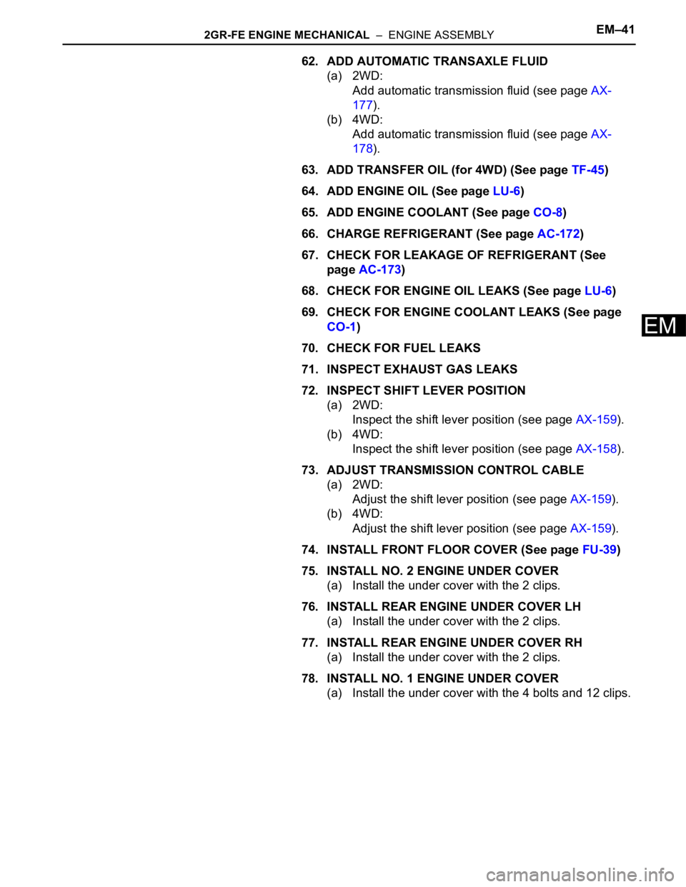
62. ADD AUTOMATIC TRANSAXLE FLUID
(a) 2WD:
Add automatic transmission fluid (see page AX-
177).
(b) 4WD:
Add automatic transmission fluid (see page AX-
178).
63. ADD TRANSFER OIL (for 4WD) (See page TF-45)
64. ADD ENGINE OIL (See page LU-6)
65. ADD ENGINE COOLANT (See page CO-8)
66. CHARGE REFRIGERANT (See page AC-172)
67. CHECK FOR LEAKAGE OF REFRIGERANT (See
page AC-173)
68. CHECK FOR ENGINE OIL LEAKS (See page LU-6)
69. CHECK FOR ENGINE COOLANT LEAKS (See page
CO-1)
70. CHECK FOR FUEL LEAKS
71. INSPECT EXHAUST GAS LEAKS
72. INSPECT SHIFT LEVER POSITION
(a) 2WD:
Inspect the shift lever position (see page AX-159).
(b) 4WD:
Inspect the shift lever position (see page AX-158).
73. ADJUST TRANSMISSION CONTROL CABLE
(a) 2WD:
Adjust the shift lever position (see page AX-159).
(b) 4WD:
Adjust the shift lever position (see page AX-159).
74. INSTALL FRONT FLOOR COVER (See page FU-39)
75. INSTALL NO. 2 ENGINE UNDER COVER
(a) Install the under cover with the 2 clips.
76. INSTALL REAR ENGINE UNDER COVER LH
(a) Install the under cover with the 2 clips.
77. INSTALL REAR ENGINE UNDER COVER RH
(a) Install the under cover with the 2 clips.
78. INSTALL NO. 1 ENGINE UNDER COVER
(a) Install the under cover with the 4 bolts and 12 clips.
Page 946 of 2000

AX–12U140F AUTOMATIC TRANSAXLE – AUTOMATIC TRANSAXLE SYSTEM
AX
NEXT
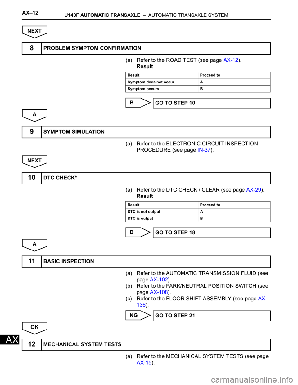
(a) Refer to the ROAD TEST (see page AX-12).
Result
B
A
(a) Refer to the ELECTRONIC CIRCUIT INSPECTION
PROCEDURE (see page IN-37).
NEXT
(a) Refer to the DTC CHECK / CLEAR (see page AX-29).
Result
B
A
(a) Refer to the AUTOMATIC TRANSMISSION FLUID (see
page AX-102).
(b) Refer to the PARK/NEUTRAL POSITION SWITCH (see
page AX-108).
(c) Refer to the FLOOR SHIFT ASSEMBLY (see page AX-
136).
NG
OK
(a) Refer to the MECHANICAL SYSTEM TESTS (see page
AX-15).
8PROBLEM SYMPTOM CONFIRMATION
Result Proceed to
Symptom does not occur A
Symptom occurs B
GO TO STEP 10
9SYMPTOM SIMULATION
10DTC CHECK*
Result Proceed to
DTC is not output A
DTC is output B
GO TO STEP 18
11BASIC INSPECTION
GO TO STEP 21
12MECHANICAL SYSTEM TESTS
Page 952 of 2000

AX–18U140F AUTOMATIC TRANSAXLE – AUTOMATIC TRANSAXLE SYSTEM
AX
MECHANICAL SYSTEM TESTS
1. STALL SPEED TEST
HINT:
This test is to check the overall performance of the
engine and transaxle.
NOTICE:
• Do not perform the stall speed test longer than 5
seconds.
• To ensure safety, perform this test in an open and
level area that provides good traction.
• The stall speed test should always be performed
with at least 2 people. One person should observe
the condition of the wheels and wheel chocks
while the other is performing the test.
(a) Connect the intelligent tester to the CAN VIM. Then
connect the CAN VIM to the DLC3.
(b) Run the vehicle until the transmission fluid
temperature has reached 50 to 80
C (122 to 176F).
(c) Allow the engine to idle with the air conditioning
OFF.
(d) Chock all 4 wheels.
(e) Set the parking brake and keep the brake pedal
depressed firmly with your left foot.
(f) Move the shift lever to the D position.
(g) Depress the accelerator pedal as much as possible
with your right foot.
(h) Read the engine rpm (stall speed) and release the
accelerator pedal immediately.
Standard value:
2,150 to 2,450 rpm
Evaluation:
NOTICE:
Perform the test at the normal operating ATF
temperature of 50 to 80
C (122 to 176F).
2. SHIFT TIME LAG TEST
HINT:
This test is to check the condition of the direct clutch,
forward clutch, 1st brake and reverse brake.
(a) Connect the intelligent tester to the CAN VIM. Then
connect the CAN VIM to the DLC3.
(b) Run the vehicle until the transmission fluid
temperature has reached 50 to 80
C (122 to 176F).
(c) Allow the engine to idle with the air conditioning
OFF.
Test Result Possible Cause
Stall speed is lower than standard value • Stator one-way clutch is not operating properly
• Torque converter is faulty (stall speed is less than standard value
by 600 rpm or more)
• Engine power may be insufficient
Stall speed is higher than standard value • Line pressure is low
• C1 clutch slipping
• F3 one-way clutch is not operating properly
• F4 one-way clutch is not operating properly
Page 1028 of 2000

AX–12U151E AUTOMATIC TRANSAXLE – AUTOMATIC TRANSAXLE SYSTEM
AX
NEXT
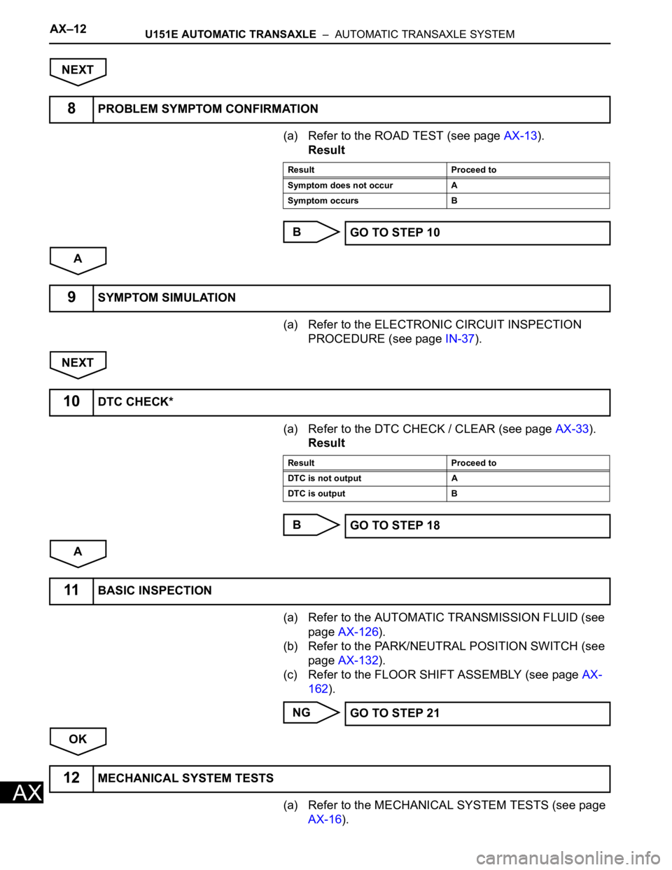
(a) Refer to the ROAD TEST (see page AX-13).
Result
B
A
(a) Refer to the ELECTRONIC CIRCUIT INSPECTION
PROCEDURE (see page IN-37).
NEXT
(a) Refer to the DTC CHECK / CLEAR (see page AX-33).
Result
B
A
(a) Refer to the AUTOMATIC TRANSMISSION FLUID (see
page AX-126).
(b) Refer to the PARK/NEUTRAL POSITION SWITCH (see
page AX-132).
(c) Refer to the FLOOR SHIFT ASSEMBLY (see page AX-
162).
NG
OK
(a) Refer to the MECHANICAL SYSTEM TESTS (see page
AX-16).
8PROBLEM SYMPTOM CONFIRMATION
Result Proceed to
Symptom does not occur A
Symptom occurs B
GO TO STEP 10
9SYMPTOM SIMULATION
10DTC CHECK*
Result Proceed to
DTC is not output A
DTC is output B
GO TO STEP 18
11BASIC INSPECTION
GO TO STEP 21
12MECHANICAL SYSTEM TESTS
Page 1034 of 2000

AX–18U151E AUTOMATIC TRANSAXLE – AUTOMATIC TRANSAXLE SYSTEM
AX
MECHANICAL SYSTEM TESTS
1. STALL SPEED TEST
HINT:
This test is to check the overall performance of the
engine and transaxle.
NOTICE:
• Do not perform the stall speed test longer than 10
seconds.
• To ensure safety, perform this test in an open and
level area that provides good traction.
• The stall speed test should always be performed
with at least 2 people. One person should observe
the condition of the wheels and wheel chocks
while the other is performing the test.
(a) Connect the intelligent tester to the CAN VIM. Then
connect the CAN VIM to the DLC3.
(b) Run the vehicle until the transmission fluid
temperature has reached 50 to 80
C (122 to 176F).
(c) Allow the engine to idle with the air conditioning
OFF.
(d) Chock all 4 wheels.
(e) Set the parking brake and keep the brake pedal
depressed firmly with your left foot.
(f) Move the shift lever to the D position.
(g) Depress the accelerator pedal as much as possible
with your right foot.
(h) Read the engine rpm (stall speed) and release the
accelerator pedal immediately.
Standard value:
2,030 to 2,330 rpm
Evaluation:
NOTICE:
Perform the test at the normal operating ATF
temperature of 50 to 80
C (122 to 176F).
2. SHIFT TIME LAG TEST
HINT:
This test is to check the condition of the direct clutch,
forward clutch, 1st brake and reverse brake.
(a) Connect the intelligent tester to the CAN VIM. Then
connect the CAN VIM to the DLC3.
(b) Run the vehicle until the transmission fluid
temperature has reached 50 to 80
C (122 to 176F).
Test Result Possible Cause
Stall speed is lower than standard value • Engine power output may be insufficient
• Stator one-way clutch not operating properly
HINT:
If the value is less than the specified value by 600 rpm or more, the
torque converter could be faulty.
Stall speed is higher than standard value • Line pressure is too low
• Forward clutch slipping
• U/D (underdrive) brake slipping
• U/D (underdrive) one-way clutch is not operating properly
• No. 1 one-way clutch not operating properly
• Improper fluid level
Page 1036 of 2000

AX–20U151E AUTOMATIC TRANSAXLE – AUTOMATIC TRANSAXLE SYSTEM
AX
HYDRAULIC TEST
1. PERFORM HYDRAULIC TEST
(a) Measure the line pressure.
NOTICE:
• Perform the test at the normal operating ATF
temperature: 50 to 80
C (122 to 176F).
• The line pressure test should always be
performed with at least 2 people. One person
should observe the condition of the wheels or
wheel chocks while the other is performing
the test.
• Be careful to prevent SST's hose from
interfering with the exhaust pipe.
• This test must be performed after checking
and adjusting the engine.
• Perform the test with the A/C OFF.
• When conducting the stall test, do not
continue for more than 10 seconds.
(1) Warm up the ATF (Automatic Transmission
Fluid).
(2) Lift the vehicle up.
(3) Remove the engine under cover.
(4) Connect the intelligent tester to the DLC3.
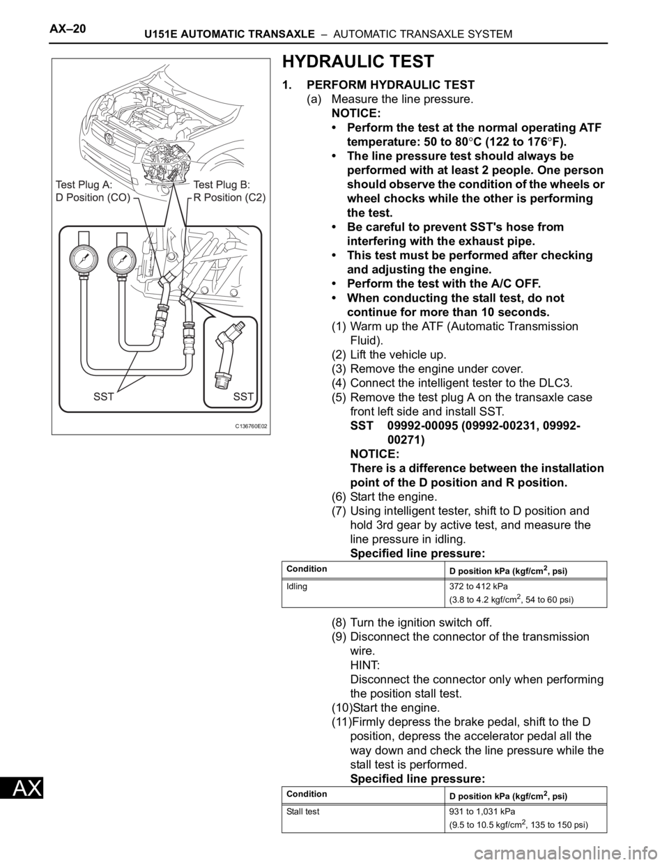
(5) Remove the test plug A on the transaxle case
front left side and install SST.
SST 09992-00095 (09992-00231, 09992-
00271)
NOTICE:
There is a difference between the installation
point of the D position and R position.
(6) Start the engine.
(7) Using intelligent tester, shift to D position and
hold 3rd gear by active test, and measure the
line pressure in idling.
Specified line pressure:
(8) Turn the ignition switch off.
(9) Disconnect the connector of the transmission
wire.
HINT:
Disconnect the connector only when performing
the position stall test.
(10)Start the engine.
(11)Firmly depress the brake pedal, shift to the D
position, depress the accelerator pedal all the
way down and check the line pressure while the
stall test is performed.
Specified line pressure:
C136760E02
Condition
D position kPa (kgf/cm2, psi)
Idling 372 to 412 kPa
(3.8 to 4.2 kgf/cm
2, 54 to 60 psi)
Condition
D position kPa (kgf/cm
2, psi)
Stall test 931 to 1,031 kPa
(9.5 to 10.5 kgf/cm
2, 135 to 150 psi)
Page 1037 of 2000

U151E AUTOMATIC TRANSAXLE – AUTOMATIC TRANSAXLE SYSTEMAX–21
AX
(12)Turn the ignition switch off.
(13)Remove SST, and install the test plug A.
(14)Remove the test plug B, install SST and start
the engine.
SST 09992-00095 (09992-00231, 09992-
00271)
(15)Connect the transmission wire connector,
depress the brake pedal firmly, shift to the R
position and check the line pressure while the
engine is idling and during the stall test.
Specified line pressure:
(16)Remove SST, and install the test plug B.
(17)Clear the DTC.
Evaluation:
Condition
R position kPa (kgf/cm2, psi)
Idling 672 to 742 kPa
(6.9 to 7.6 kgf/cm
2, 97 to 108 psi)
Stall test 1,768 to 1,968 kPa
(18.0 to 20.0 kgf/cm
2, 256 to 285 psi)
Problem Possible cause
Measured values at all positions are higher than specified • Shift solenoid valve SLT defective
• Regulator valve defective
Measured values at all positions are lower than specified • Shift solenoid valve SLT defective
• Regulator valve defective
• Oil pump defective
• U/D (underdrive) direct clutch defective
Pressure is low when shift lever is on D only • D position circuit fluid leak
• Forward clutch defective
Pressure is low when shift lever is on R only • R position circuit fluid leak
• Reverse clutch defective
• 1st and reverse brake defective