Page 186 of 2000
2AZ-FE ENGINE CONTROL SYSTEM – ECMES–429
ES
REMOVAL
1. DISCONNECT CABLE FROM NEGATIVE BATTERY
TERMINAL
CAUTION:
Wait at least 90 seconds after disconnecting the
cable from the negative (-) battery terminal to
prevent airbag and seat belt pretensioner activation.
2. REMOVE AIR CLEANER CAP (See page ES-411)
3. REMOVE AIR CLEANER CASE
(a) Disconnect the harness clamp.
(b) Remove the 3 bolts and air cleaner case.
4. REMOVE ECM
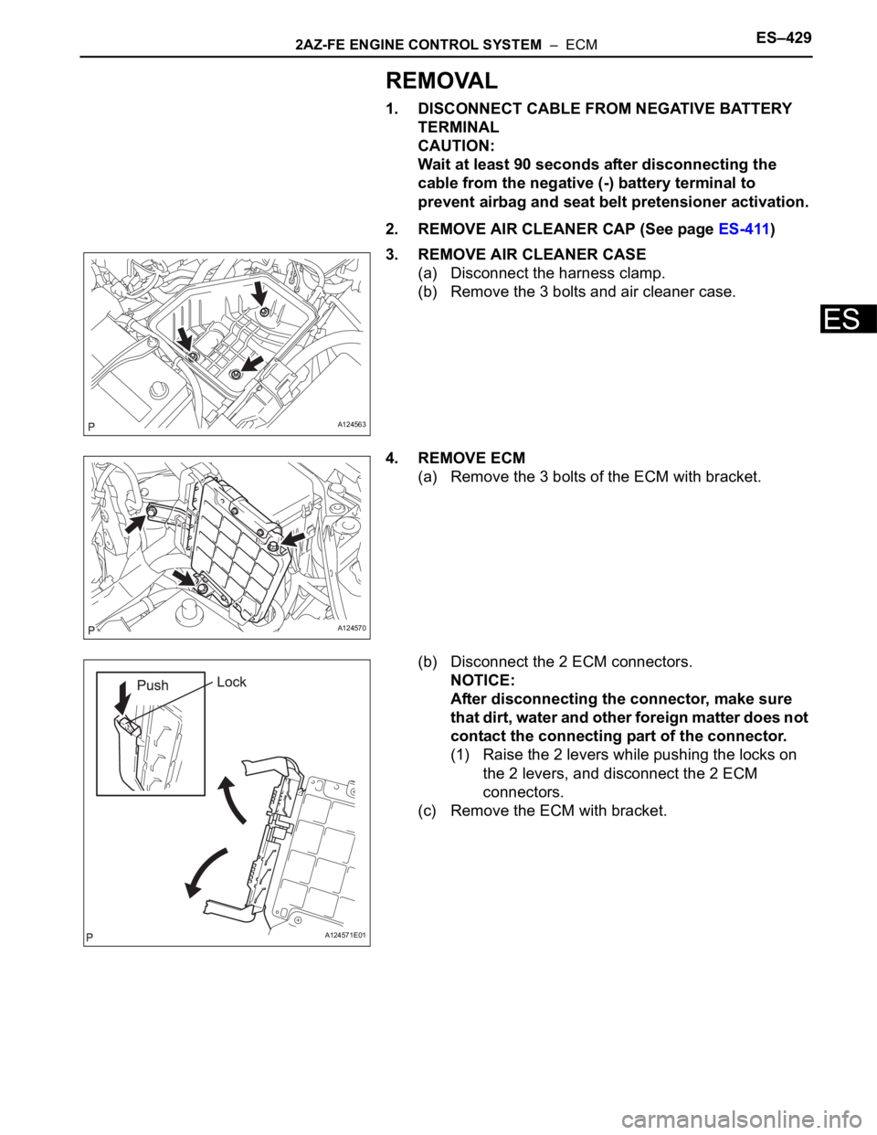
(a) Remove the 3 bolts of the ECM with bracket.
(b) Disconnect the 2 ECM connectors.
NOTICE:
After disconnecting the connector, make sure
that dirt, water and other foreign matter does not
contact the connecting part of the connector.
(1) Raise the 2 levers while pushing the locks on
the 2 levers, and disconnect the 2 ECM
connectors.
(c) Remove the ECM with bracket.
A124563
A124570
A124571E01
Page 193 of 2000
ES–4702GR-FE ENGINE CONTROL SYSTEM – ECM
ES
REMOVAL
1. DISCONNECT CABLE FROM NEGATIVE BATTERY
TERMINAL
CAUTION:
Wait at least 90 seconds after disconnecting the
cable from the negative (-) battery terminal to
prevent airbag and seat belt pretensioner activation.
2. REMOVE AIR CLEANER CAP (See page EM-23)
3. REMOVE AIR CLEANER CASE (See page EM-23)
4. REMOVE ECM
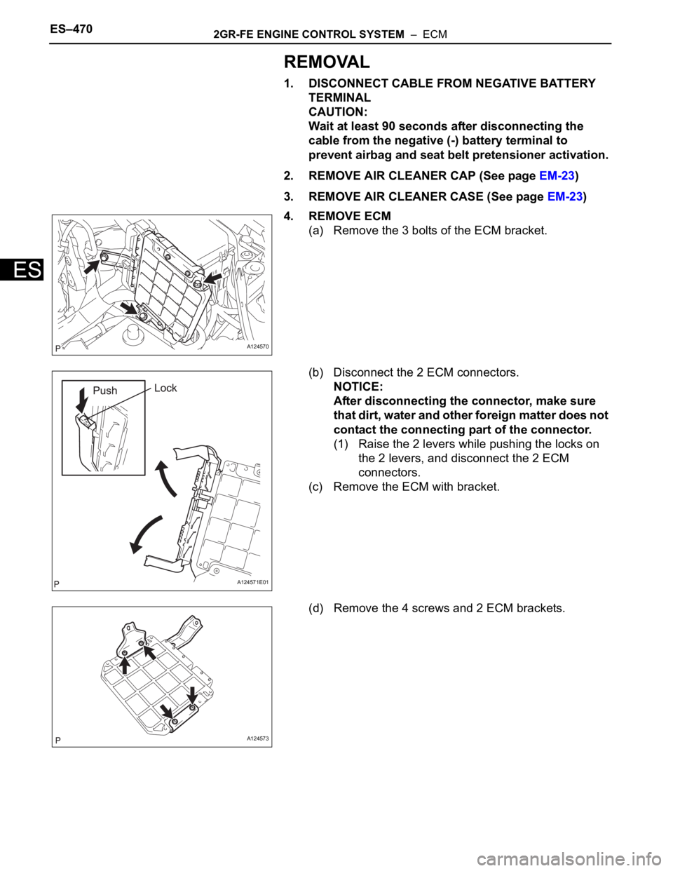
(a) Remove the 3 bolts of the ECM bracket.
(b) Disconnect the 2 ECM connectors.
NOTICE:
After disconnecting the connector, make sure
that dirt, water and other foreign matter does not
contact the connecting part of the connector.
(1) Raise the 2 levers while pushing the locks on
the 2 levers, and disconnect the 2 ECM
connectors.
(c) Remove the ECM with bracket.
(d) Remove the 4 screws and 2 ECM brackets.
A124570
A124571E01
A124573
Page 196 of 2000

2GR-FE ENGINE MECHANICAL – ENGINE ASSEMBLYEM–21
EM
REMOVAL
1. DISCHARGE REFRIGERANT FROM
REFRIGERATION SYSTEM (See page AC-172)
2. DISCHARGE FUEL SYSTEM PRESSURE (See page
FU-13)
3. DISCONNECT CABLE FROM NEGATIVE BATTERY
TERMINAL
CAUTION:
Wait at least 90 seconds after disconnecting the
cable from the negative (-) battery terminal to
prevent airbag and seat belt pretensioner activation.
4. REMOVE NO. 1 ENGINE UNDER COVER
(a) Remove the 4 bolts, 12 clips and under cover.
5. REMOVE REAR ENGINE UNDER COVER RH
(a) Remove the 2 clips and under cover.
6. REMOVE REAR ENGINE UNDER COVER LH
(a) Remove the 2 clips and under cover.
7. REMOVE NO. 2 ENGINE UNDER COVER
(a) Remove the 2 clips and under cover.
8. REMOVE FRONT FLOOR COVER (See page FU-34)
9. DRAIN ENGINE COOLANT (See page CO-8)
10. DRAIN ENGINE OIL (See page LU-4)
11. DRAIN AUTOMATIC TRANSAXLE FLUID
(a) 2WD:
Drain automatic transaxle fluid (see page AX-172).
(b) 4WD:
Drain automatic transaxle fluid (see page AX-173)
12. DRAIN TRANSFER OIL (for 4WD)
13. REMOVE HOOD SUB-ASSEMBLY (See page ED-4)
14. REMOVE V-BANK COVER SUB-ASSEMBLY
(a) Detach the 3 clips and remove the V-bank cover.
A137900
Page 247 of 2000
LU–122GR-FE LUBRICATION – OIL PUMP
LU
REMOVAL
1. DISCHARGE FUEL SYSTEM PRESSURE (See page
FU-9)
2. DISCONNECT CABLE FROM NEGATIVE BATTERY
TERMINAL
CAUTION:
Wait at least 90 seconds after disconnecting the
cable from the negative (-) battery terminal to
prevent airbag and seat belt pretensioner activation.
3. REMOVE ENGINE ASSEMBLY
(a) Remove the engine from the vehicle (see page EM-
21).
4. INSTALL ENGINE TO STAND
5. REMOVE NO. 2 OIL DIPSTICK GUIDE
(a) Remove the oil dipstick.
(b) Remove the bolt and dipstick guide.
6. REMOVE OIL DIPSTICK GUIDE
(a) Remove the bolt and dipstick guide.
7. REMOVE OIL FILTER CAP ASSEMBLY (See page LU-
4)
8. REMOVE OIL FILTER ELEMENT KIT (See page LU-5)
9. REMOVE NO. 2 OIL PAN SUB-ASSEMBLY
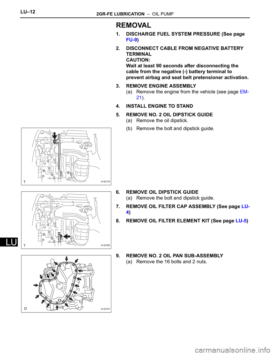
(a) Remove the 16 bolts and 2 nuts.
A132179
A132180
A132107
Page 347 of 2000
AX–136U140F AUTOMATIC TRANSAXLE – FLOOR SHIFT ASSEMBLY
AX
REMOVAL
1. DISCONNECT CABLE FROM NEGATIVE BATTERY
TERMINAL
CAUTION:
Wait at least 90 seconds after disconnecting the
cable from the negative (-) battery terminal to
prevent airbag and seat belt pretensioner activation.
2. REMOVE SHIFT LEVER KNOB SUB-ASSEMBLY
3. REMOVE REAR CONSOLE BOX SUB-ASSEMBLY
(a) Remove the console box (see page IP-20).
4. DISCONNECT TRANSAXLE CONTROL CABLE
ASSEMBLY
(a) Disconnect the control cable from the shift lever.
(b) Turn the nut and disconnect the control cable from
the shift lever retainer.
5. REMOVE FLOOR SHIFT ASSEMBLY
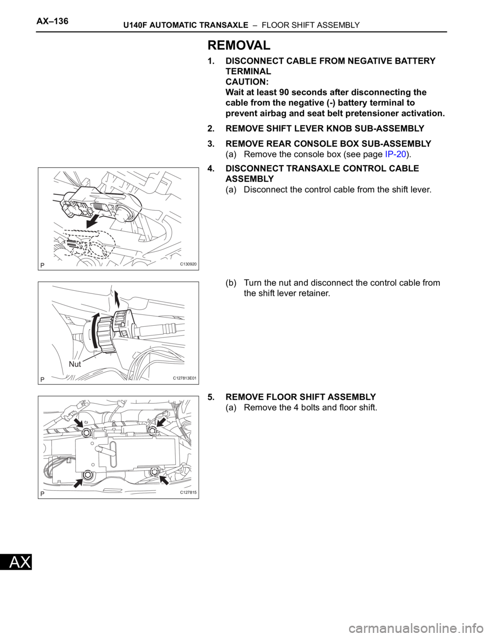
(a) Remove the 4 bolts and floor shift.
C130920
C127813E01
C127815
Page 355 of 2000
AX–162U151E AUTOMATIC TRANSAXLE – FLOOR SHIFT ASSEMBLY
AX
REMOVAL
1. DISCONNECT CABLE FROM NEGATIVE BATTERY
TERMINAL
CAUTION:
Wait at least 90 seconds after disconnecting the
cable from the negative (-) battery terminal to
prevent airbag and seat belt pretensioner activation.
2. REMOVE SHIFT LEVER KNOB SUB-ASSEMBLY
3. REMOVE REAR CONSOLE BOX SUB-ASSEMBLY
(a) Remove the console box (see page IP-26).
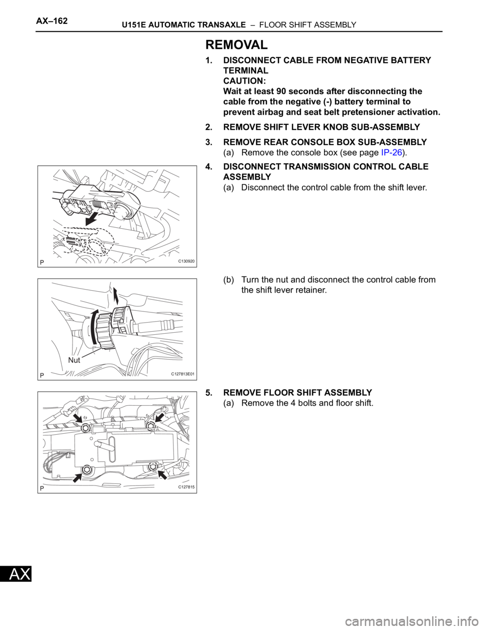
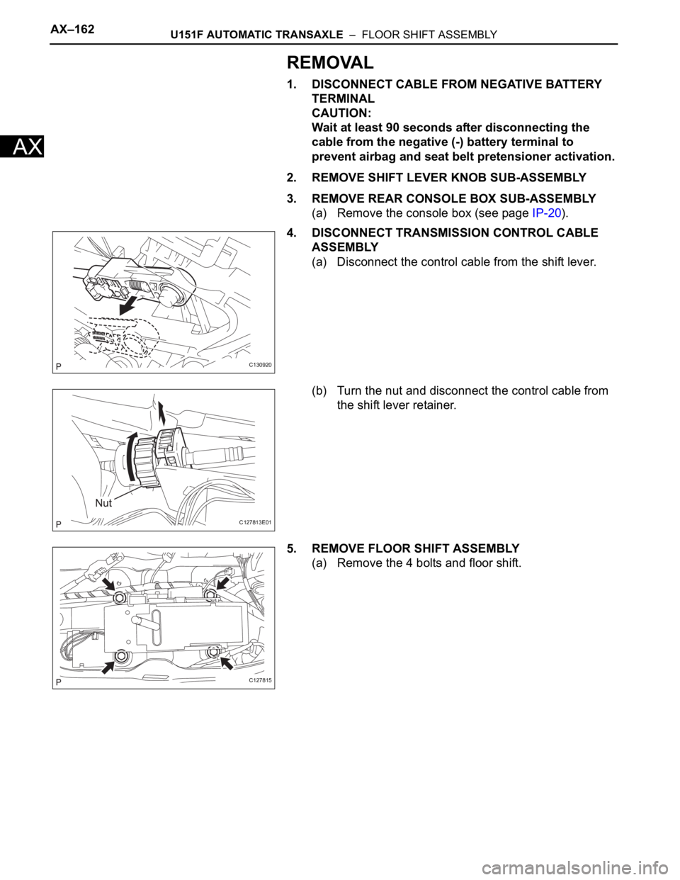
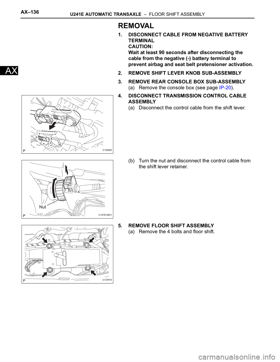
4. DISCONNECT TRANSMISSION CONTROL CABLE
ASSEMBLY
(a) Disconnect the control cable from the shift lever.
(b) Turn the nut and disconnect the control cable from
the shift lever retainer.
5. REMOVE FLOOR SHIFT ASSEMBLY
(a) Remove the 4 bolts and floor shift.
C130920
C127813E01
C127815
Page 361 of 2000
AX–162U151F AUTOMATIC TRANSAXLE – FLOOR SHIFT ASSEMBLY
AX
REMOVAL
1. DISCONNECT CABLE FROM NEGATIVE BATTERY
TERMINAL
CAUTION:
Wait at least 90 seconds after disconnecting the
cable from the negative (-) battery terminal to
prevent airbag and seat belt pretensioner activation.
2. REMOVE SHIFT LEVER KNOB SUB-ASSEMBLY
3. REMOVE REAR CONSOLE BOX SUB-ASSEMBLY
(a) Remove the console box (see page IP-20).
4. DISCONNECT TRANSMISSION CONTROL CABLE
ASSEMBLY
(a) Disconnect the control cable from the shift lever.
(b) Turn the nut and disconnect the control cable from
the shift lever retainer.
5. REMOVE FLOOR SHIFT ASSEMBLY
(a) Remove the 4 bolts and floor shift.
C130920
C127813E01
C127815
Page 373 of 2000
AX–136U241E AUTOMATIC TRANSAXLE – FLOOR SHIFT ASSEMBLY
AX
REMOVAL
1. DISCONNECT CABLE FROM NEGATIVE BATTERY
TERMINAL
CAUTION:
Wait at least 90 seconds after disconnecting the
cable from the negative (-) battery terminal to
prevent airbag and seat belt pretensioner activation.
2. REMOVE SHIFT LEVER KNOB SUB-ASSEMBLY
3. REMOVE REAR CONSOLE BOX SUB-ASSEMBLY
(a) Remove the console box (see page IP-20).
4. DISCONNECT TRANSMISSION CONTROL CABLE
ASSEMBLY
(a) Disconnect the control cable from the shift lever.
(b) Turn the nut and disconnect the control cable from
the shift lever retainer.
5. REMOVE FLOOR SHIFT ASSEMBLY
(a) Remove the 4 bolts and floor shift.
C130920
C127813E01
C127815