Page 79 of 2000

ENGINE - 2GR-FE ENGINE
285EG21
Timing Chain Cover
Wa t e r P u m p G a s k e t
Wa t e r P u m pWater Pump Swirl
Chamber
Oil Pump
Housing
Oil Pump RotorsTiming Chain
Cover
Oil Pump Chamber
View from Front Side View from Back Side
285EG22
Oil
Passage
Check Ball
Check Ball
Spring
Plunger SpringPlunger
Roller Rocker ArmCam
Oil
Passage
Hydraulic
Lash Adjuster
Service Tip
Valve clearance adjustment is not necessary because a hydraulic lash adjuster is used in this model.
EG-83
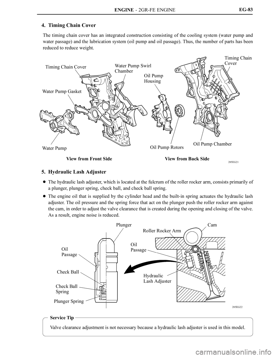
4. Timing Chain Cover
The timing chain cover has an integrated construction consisting of the cooling system (water pump and
water passage) and the lubrication system (oil pump and oil passage). Thus, the number of parts has been
reduced to reduce weight.
5. Hydraulic Lash Adjuster
The hydraulic lash adjuster, which is located at the fulcrum of the roller rocker arm, consists primarily of
a plunger, plunger spring, check ball, and check ball spring.
The engine oil that is supplied by the cylinder head and the built-in spring actuates the hydraulic lash
adjuster. The oil pressure and the spring force that act on the plunger push the roller rocker arm against
the cam, in order to adjust the valve clearance that is created during the opening and closing of the valve.
As a result, engine noise is reduced.
Page 82 of 2000
ENGINE - 2GR-FE ENGINE
285EG24
Timing Chain Cover
Oil Pump
Housing
Oil Pump Rotors
(Cycloid Rotor)Crankshaft
To Cylinder
Block
From Oil
Filter
To
Oil FilterFrom
Oil Strainer
Oil passage in the oil pump
285EG25
Oil Jet Cross Section
Oil JetsCheck
Va l v eEngine Oil EG-86
2. Oil Pump
A compact cycloid rotor type oil pump directly driven by the crankshaft is used.
This oil pump has used an internal relief method which circulates relief oil to the suction passage in the
oil pump. This aims to minimize oil level change in the oil pan, reduce friction, and reduce air mixing rate
in the oil.
3. Oil Jet
Oil jets for cooling and lubricating the pistons have been provided in the cylinder block, in the center of
the right and left banks.
These oil jets contain a check valve to prevent oil from being fed when the oil pressure is low. This prevents
the overall oil pressure in the engine from dropping.
Page 250 of 2000
2GR-FE LUBRICATION – OIL PUMPLU–15
LU
(c) Remove the gasket.
DISASSEMBLY
1. REMOVE OIL PUMP RELIEF VALVE
(a) Using a 27 mm socket wrench, remove the plug.
(b) Remove the valve spring and oil pump relief valve.
2. REMOVE OIL PUMP COVER
(a) Remove the 8 bolts, oil pump cover, drive rotor and
driven rotor.
NOTICE:
Be careful not to damage the drive and driven
rotors.
A132100
A132097
A131927
Page 385 of 2000
SERVICE SPECIFICATIONS – 2GR-FE ENGINE MECHANICALSS–23
SS
Cylinder head cover x
Cylinder head
(for Bank 1)for Bolt A 21 214 15
for Except bolt A 10 102 7
Oil pipe bracket x Cylinder head (for Bank 1) 10 102 7
Oil pipe union bolt x Cylinder head cover
(for Bank 1)65 663 48
Oil pipe union bolt x Cylinder head
(for Bank 1)65 663 48
Cylinder head cover x
Cylinder headfor Bolt A 21 214 15
for Except bolt A 10 102 7
No. 1 oil pipe union bolt x Cylinder head cover (for Bank
2)65 663 48
No. 1 oil pipe union bolt x Cylinder head (for Bank 2) 65 663 48
Water outlet x Cylinder head 10 102 7
Camshaft timing oil control valve x Cylinder head cover 10 102 7
VVT sensor x Cylinder head cover 10 102 7
Spark plug x Cylinder head 18 184 13 Part Tightened N*m kgf*cm ft.*lbf
Page 689 of 2000
EM–522GR-FE ENGINE MECHANICAL – ENGINE UNIT
EM
DISASSEMBLY
1. REMOVE OIL FILLER CAP SUB-ASSEMBLY
2. REMOVE SPARK PLUG
3. REMOVE CAMSHAFT TIMING CONTROL VALVE
ASSEMBLY (See page ES-440)
4. REMOVE VVT SENSOR (See page ES-443)
5. REMOVE WATER OUTLET
(a) Remove the 2 bolts, 4 nuts and water outlet.
(b) Remove the 2 gaskets and O-ring.
6. REMOVE OIL PIPE
(a) Remove the bolt, 2 union bolts and oil pipe.
(b) Remove the oil control valve filter RH and gaskets.
7. REMOVE CYLINDER HEAD COVER SUB-ASSEMBLY
(for Bank 1)
(a) Remove the 12 bolts, cylinder head cover and
gasket.
HINT:
Make sure the removed parts are returned to the
same places they were remove a from.
A129676
A129677
A132173
A132119
Page 690 of 2000
2GR-FE ENGINE MECHANICAL – ENGINE UNITEM–53
EM
8. REMOVE NO. 1 OIL PIPE
(a) Remove the 2 union bolts and oil pipe.
(b) Remove the oil control valve filter LH and gaskets.
9. REMOVE CYLINDER HEAD COVER SUB-ASSEMBLY
(for Bank 2)
(a) Remove the 12 bolts, cylinder head cover and
gasket.
HINT:
Make sure the removed parts are returned to the
same places they were remove a from.
10. REMOVE FRONT NO. 1 ENGINE MOUNTING
BRACKET
(a) Remove the 6 bolts and mounting bracket.
11. REMOVE WATER INLET HOUSING (See page CO-12)
12. REMOVE OIL FILTER CAP ASSEMBLY (See page LU-
4)
13. REMOVE OIL FILTER ELEMENT (See page LU-5)
14. REMOVE NO. 2 OIL PAN SUB-ASSEMBLY (See page
LU-12)
15. REMOVE OIL STRAINER SUB-ASSEMBLY (See page
LU-13)
16. REMOVE OIL PAN SUB-ASSEMBLY (See page LU-13)
17. REMOVE OIL PAN BAFFLE PLATE
(a) Remove the 7 bolts and baffle plate.
A132070
A132120
A136827
A129685
Page 765 of 2000

EM–1282GR-FE ENGINE MECHANICAL – ENGINE UNIT
EM
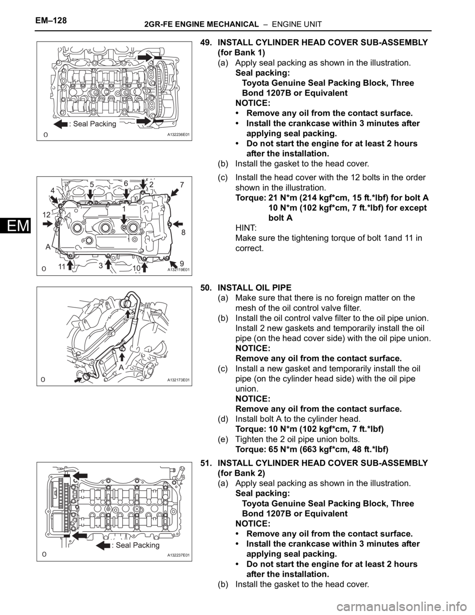
49. INSTALL CYLINDER HEAD COVER SUB-ASSEMBLY
(for Bank 1)
(a) Apply seal packing as shown in the illustration.
Seal packing:
Toyota Genuine Seal Packing Block, Three
Bond 1207B or Equivalent
NOTICE:
• Remove any oil from the contact surface.
• Install the crankcase within 3 minutes after
applying seal packing.
• Do not start the engine for at least 2 hours
after the installation.
(b) Install the gasket to the head cover.
(c) Install the head cover with the 12 bolts in the order
shown in the illustration.
Torque: 21 N*m (214 kgf*cm, 15 ft.*lbf) for bolt A
10 N*m (102 kgf*cm, 7 ft.*lbf) for except
bolt A
HINT:
Make sure the tightening torque of bolt 1and 11 in
correct.
50. INSTALL OIL PIPE
(a) Make sure that there is no foreign matter on the
mesh of the oil control valve filter.
(b) Install the oil control valve filter to the oil pipe union.
Install 2 new gaskets and temporarily install the oil
pipe (on the head cover side) with the oil pipe union.
NOTICE:
Remove any oil from the contact surface.
(c) Install a new gasket and temporarily install the oil
pipe (on the cylinder head side) with the oil pipe
union.
NOTICE:
Remove any oil from the contact surface.
(d) Install bolt A to the cylinder head.
Torque: 10 N*m (102 kgf*cm, 7 ft.*lbf)
(e) Tighten the 2 oil pipe union bolts.
Torque: 65 N*m (663 kgf*cm, 48 ft.*lbf)
51. INSTALL CYLINDER HEAD COVER SUB-ASSEMBLY
(for Bank 2)
(a) Apply seal packing as shown in the illustration.
Seal packing:
Toyota Genuine Seal Packing Block, Three
Bond 1207B or Equivalent
NOTICE:
• Remove any oil from the contact surface.
• Install the crankcase within 3 minutes after
applying seal packing.
• Do not start the engine for at least 2 hours
after the installation.
(b) Install the gasket to the head cover.
A132236E01
A132119E01
A132173E01
A132237E01
Page 766 of 2000

2GR-FE ENGINE MECHANICAL – ENGINE UNITEM–129
EM
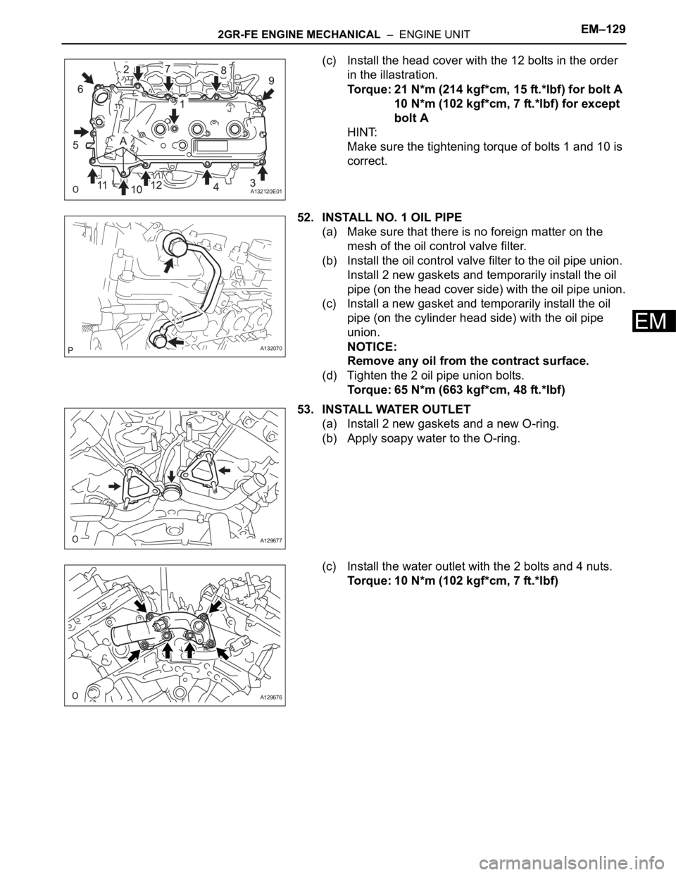
(c) Install the head cover with the 12 bolts in the order
in the illastration.
Torque: 21 N*m (214 kgf*cm, 15 ft.*lbf) for bolt A
10 N*m (102 kgf*cm, 7 ft.*lbf) for except
bolt A
HINT:
Make sure the tightening torque of bolts 1 and 10 is
correct.
52. INSTALL NO. 1 OIL PIPE
(a) Make sure that there is no foreign matter on the
mesh of the oil control valve filter.
(b) Install the oil control valve filter to the oil pipe union.
Install 2 new gaskets and temporarily install the oil
pipe (on the head cover side) with the oil pipe union.
(c) Install a new gasket and temporarily install the oil
pipe (on the cylinder head side) with the oil pipe
union.
NOTICE:
Remove any oil from the contract surface.
(d) Tighten the 2 oil pipe union bolts.
Torque: 65 N*m (663 kgf*cm, 48 ft.*lbf)
53. INSTALL WATER OUTLET
(a) Install 2 new gaskets and a new O-ring.
(b) Apply soapy water to the O-ring.
(c) Install the water outlet with the 2 bolts and 4 nuts.
Torque: 10 N*m (102 kgf*cm, 7 ft.*lbf)
A132120E01
A132070
A129677
A129676