Page 172 of 2000
PP–22PREPARATION – 2AZ-FE COOLING
PP
EQUIPMENT
Ohmmeter -
Radiator cap tester -
Thermometer -
To r q u e w r e n c h -
Slide calipers -
Heater -
Page 198 of 2000

2GR-FE ENGINE MECHANICAL – ENGINE ASSEMBLYEM–23
EM
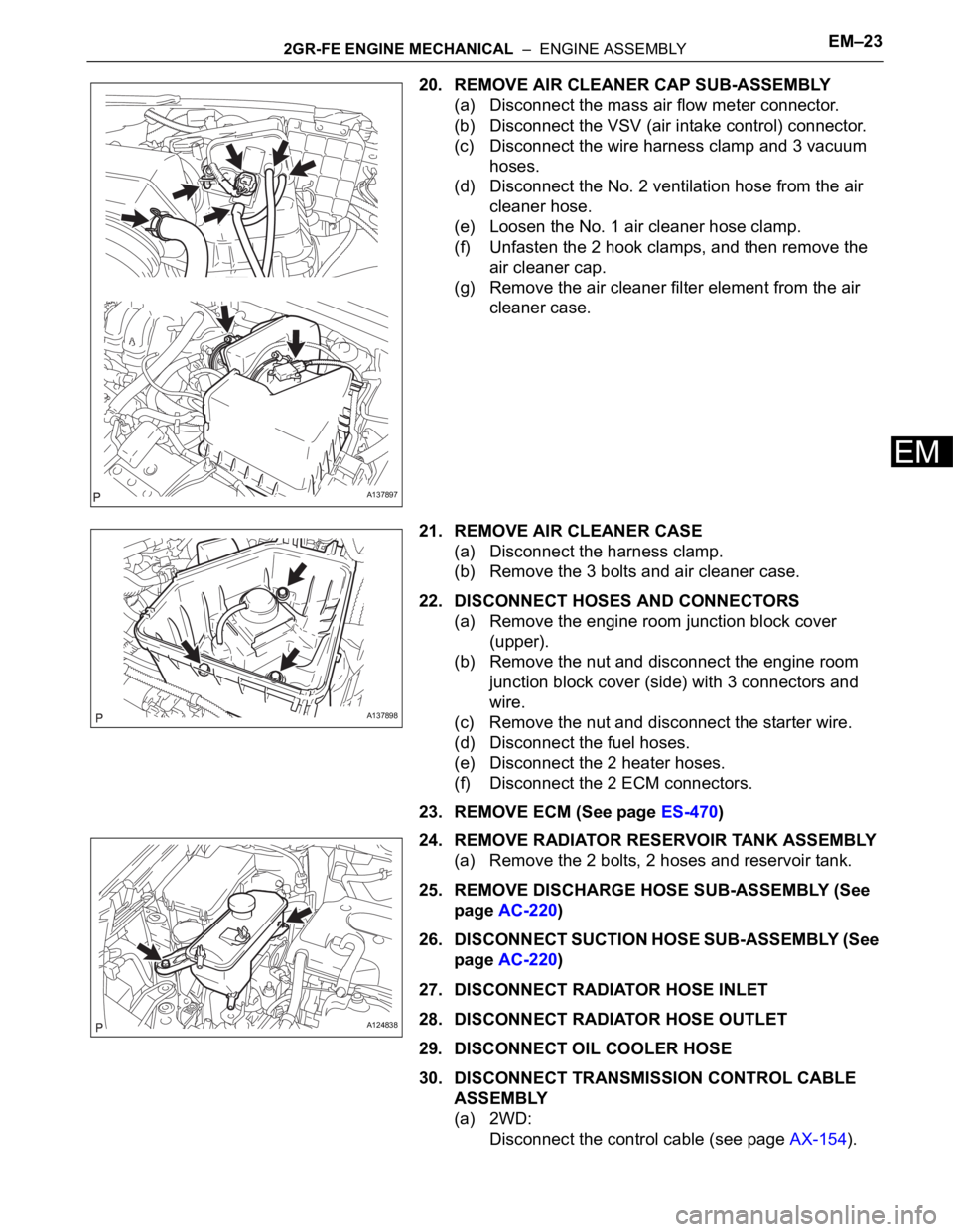
20. REMOVE AIR CLEANER CAP SUB-ASSEMBLY
(a) Disconnect the mass air flow meter connector.
(b) Disconnect the VSV (air intake control) connector.
(c) Disconnect the wire harness clamp and 3 vacuum
hoses.
(d) Disconnect the No. 2 ventilation hose from the air
cleaner hose.
(e) Loosen the No. 1 air cleaner hose clamp.
(f) Unfasten the 2 hook clamps, and then remove the
air cleaner cap.
(g) Remove the air cleaner filter element from the air
cleaner case.
21. REMOVE AIR CLEANER CASE
(a) Disconnect the harness clamp.
(b) Remove the 3 bolts and air cleaner case.
22. DISCONNECT HOSES AND CONNECTORS
(a) Remove the engine room junction block cover
(upper).
(b) Remove the nut and disconnect the engine room
junction block cover (side) with 3 connectors and
wire.
(c) Remove the nut and disconnect the starter wire.
(d) Disconnect the fuel hoses.
(e) Disconnect the 2 heater hoses.
(f) Disconnect the 2 ECM connectors.
23. REMOVE ECM (See page ES-470)
24. REMOVE RADIATOR RESERVOIR TANK ASSEMBLY
(a) Remove the 2 bolts, 2 hoses and reservoir tank.
25. REMOVE DISCHARGE HOSE SUB-ASSEMBLY (See
page AC-220)
26. DISCONNECT SUCTION HOSE SUB-ASSEMBLY (See
page AC-220)
27. DISCONNECT RADIATOR HOSE INLET
28. DISCONNECT RADIATOR HOSE OUTLET
29. DISCONNECT OIL COOLER HOSE
30. DISCONNECT TRANSMISSION CONTROL CABLE
ASSEMBLY
(a) 2WD:
Disconnect the control cable (see page AX-154).
A137897
A137898
A124838
Page 252 of 2000
PREPARATION – 2AZ-FE ENGINE MECHANICALPP–7
PP
EQUIPMENT
V-block -
Piston ring compressor -
Piston ring expander -
Valve seat cutter -
Feeler gauge -
CO/HC meter -
Connecting rod aligner -
Cylinder gauge -
Micrometer -
Precision straight edge -
Radiator cap tester -
Steel square -
Tachometer -
Torque wrench -
Vernier calipers -
Dial indicator with magnetic base -
Alignment tester -
toe-in gauge -
Spring tension gauge -
Slide calipers -
Sandpaper (#400) -
Piston heater -
Wooden block -
Plastigage -
Angle gauge -
Timing light -
Page 257 of 2000
PP–10PREPARATION – 2GR-FE ENGINE MECHANICAL
PP
EQUIPMENT
Alignment tester -
Angle gauge -
Brass bar -
Caliper gauge -
Chain block -
Compression gauge -
CO/HC meter -
Connecting rod aligner -
Cylinder gauge -
Dial indicator with magnetic base -
Engine stand -
Feeler gauge -
Gasket scraper -
Magnetic finger -
Micrometer -
Needle-nose pliers -
No. 1 engine hanger -
No. 2 engine hanger -
Pin hole grinder -
Piston ring compressor -
Piston ring expander -
Piston heater -
Plastigage -
Plastic-faced hammer -
Press -
Radiator cap tester -
Reamer (5.5 mm) -
Ridge reamer -
Rod aligner -
Sandpaper (#400) -
Slide calipers -
Straightedge -
Spring scale -
Spring tension gauge -
Steel square -
Tachometer -
Timing light -
Toe-in gauge -
To r q u e w r e n c h -
Valve seat cutter -
V-block -
Vernier calipers -
Vise -
Wooden block -
Page 299 of 2000
PREPARATION – 2GR-FE COOLINGPP–23
PP
EQUIPMENT
Ohmmeter -
Radiator cap tester -
Thermometer -
Torque wrench -
Side calipers -
Heater -
Page 379 of 2000

SS–12SERVICE SPECIFICATIONS – 2AZ-FE ENGINE MECHANICAL
SS
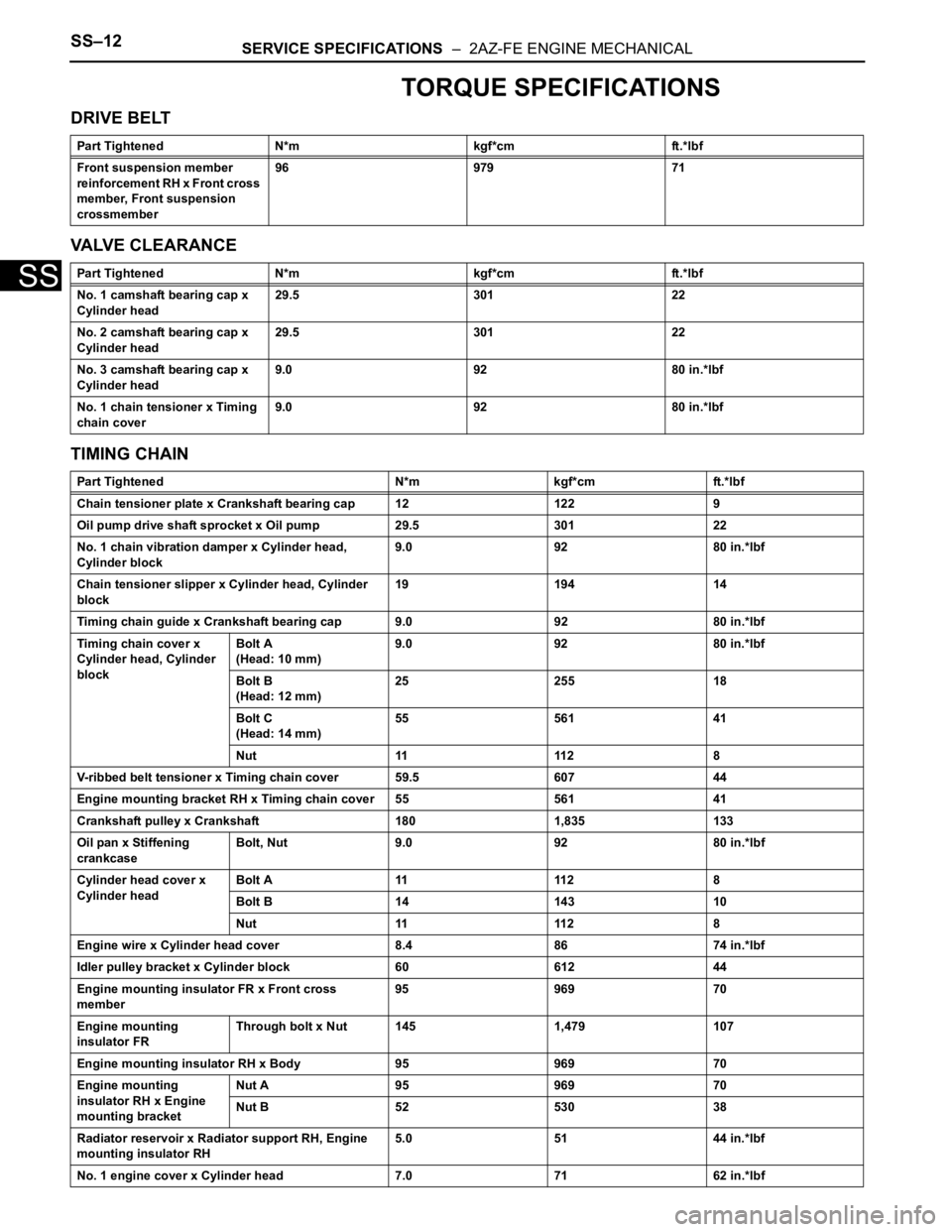
TORQUE SPECIFICATIONS
DRIVE BELT
VALVE CLEARANCE
TIMING CHAIN
Part Tightened N*m kgf*cm ft.*lbf
Front suspension member
reinforcement RH x Front cross
member, Front suspension
crossmember96 979 71
Part Tightened N*m kgf*cm ft.*lbf
No. 1 camshaft bearing cap x
Cylinder head29.5 301 22
No. 2 camshaft bearing cap x
Cylinder head29.5 301 22
No. 3 camshaft bearing cap x
Cylinder head9.0 92 80 in.*lbf
No. 1 chain tensioner x Timing
chain cover9.0 92 80 in.*lbf
Part Tightened N*m kgf*cm ft.*lbf
Chain tensioner plate x Crankshaft bearing cap 12 122 9
Oil pump drive shaft sprocket x Oil pump 29.5 301 22
No. 1 chain vibration damper x Cylinder head,
Cylinder block9.0 92 80 in.*lbf
Chain tensioner slipper x Cylinder head, Cylinder
block19 194 14
Timing chain guide x Crankshaft bearing cap 9.0 92 80 in.*lbf
Timing chain cover x
Cylinder head, Cylinder
blockBolt A
(Head: 10 mm)9.0 92 80 in.*lbf
Bolt B
(Head: 12 mm)25 255 18
Bolt C
(Head: 14 mm)55 561 41
Nut 11 112 8
V-ribbed belt tensioner x Timing chain cover 59.5 607 44
Engine mounting bracket RH x Timing chain cover 55 561 41
Crankshaft pulley x Crankshaft 180 1,835 133
Oil pan x Stiffening
crankcaseBolt, Nut 9.0 92 80 in.*lbf
Cylinder head cover x
Cylinder headBolt A 11 112 8
Bolt B 14 143 10
Nut 11 112 8
Engine wire x Cylinder head cover 8.4 86 74 in.*lbf
Idler pulley bracket x Cylinder block 60 612 44
Engine mounting insulator FR x Front cross
member95 969 70
Engine mounting
insulator FRThrough bolt x Nut 145 1,479 107
Engine mounting insulator RH x Body 95 969 70
Engine mounting
insulator RH x Engine
mounting bracketNut A 95 969 70
Nut B 52 530 38
Radiator reservoir x Radiator support RH, Engine
mounting insulator RH5.0 51 44 in.*lbf
No. 1 engine cover x Cylinder head 7.0 71 62 in.*lbf
Page 380 of 2000

SERVICE SPECIFICATIONS – 2AZ-FE ENGINE MECHANICALSS–13
SS
CYLINDER HEAD
ENGINE ASSEMBLY
Part Tightened N*m kgf*cm ft.*lbf
Camshaft position sensor x Cylinder head 9.0 92 80 in.*lbf
Oil pressure switch x Cylinder head 13 133 10
Radio setting condenser x Cylinder head 10 102 7
Cylinder head set bolt
Cylinder head x Cylinder
block1 st 70 714 52
2 nd Turn 90
Tu r n 9 0Tu r n 9 0
Camshaft timing gear x Camshaft 54 551 40
No. 2 camshaft timing sprocket x No. 2 camshaft 54 551 40
No. 1 and No. 2 camshaft bearing cap x Cylinder
head29.5 301 22
No. 3 camshaft bearing cap x Cylinder head 9.0 92 80 in.*lbf
Exhaust manifold x Cylinder head 37 377 27
No. 1 exhaust manifold heat insulator x Exhaust
manifold12 122 9
No. 1 and No. 2 manifold stay x Cylinder block,
Exhaust manifold44 449 32
Oil dipstick guide x Cylinder block 9.0 92 80 in.*lbf
Part Tightened N*m kgf*cm ft.*lbf
Drive plate x Crankshaft 98 1,000 72
Drive shaft bearing bracket x Cylinder block 64 653 47
No. 1 and No. 2 engine hanger x Cylinder head 38 387 28
Engine mounting insulator LH x Body 95 969 70
Engine mounting
insulator LHThrough bolt 56 571 41
Engine mounting insulator RH x Body 95 969 70
Engine mounting
insulator RH x Engine
mounting bracketNut A 95 969 70
Nut B 52 530 38
Engine mounting
insulator RR x Front
suspension
crossmemberBolt and Nut 95 969 70
Engine mounting
insulator RR x Engine
mounting bracketThough bolt 95 969 70
Engine mounting insulator FR x Front cross
member95 969 70
Engine mounting
insulator FRThough bolt 145 1,479 107
Battery carrier bracket x Body 20 204 15
Battery bracket reinforcement x Battery carrier 20 204 15
Front battery carrier x Battery bracket
reinforcement20 204 15
Air cleaner filter element x Body 5.0 51 44 in.*lbf
Radiator reservoir x Radiator support RH, Engine
mounting insulator RH5.0 51 44 in.*lbf
Battery clamp x Upper
Radiator supportFor bolt 8.5 87 75 in.*lbf
Battery clamp x Battery
clamp boltFor nut 5.0 51 44 in.*lbf
Page 601 of 2000

2AZ-FE ENGINE MECHANICAL – CYLINDER HEADEM–57
EM
REMOVAL
1. DISCHARGE FUEL SYSTEM PRESSURE (See page
FU-9)
2. DISCONNECT CABLE FROM NEGATIVE BATTERY
TERMINAL
CAUTION:
Wait at least 90 seconds after disconnecting the
cable from the negative (-) battery terminal to
prevent airbag and seat belt pretensioner activation.
3. REMOVE RADIATOR SUPPORT OPENING COVER
4. REMOVE FRONT WHEEL RH
5. REMOVE NO. 1 ENGINE UNDER COVER
6. REMOVE FRONT FENDER APRON RH
7. REMOVE NO. 1 ENGINE COVER (See page EM-22)
8. DRAIN ENGINE COOLANT (See page CO-6)
9. DRAIN ENGINE OIL (See page LU-4)
10. REMOVE AIR CLEANER CAP (See page ES-411)
11. REMOVE THROTTLE BODY (See page ES-412)
12. REMOVE FUEL DELIVERY PIPE SUB-ASSEMBLY
(See page FU-10)
13. REMOVE INTAKE MANIFOLD (See page ES-419)
14. REMOVE INTAKE MANIFOLD INSULATOR (See page
ES-420)
15. REMOVE FRONT EXHAUST PIPE (See page EX-3)
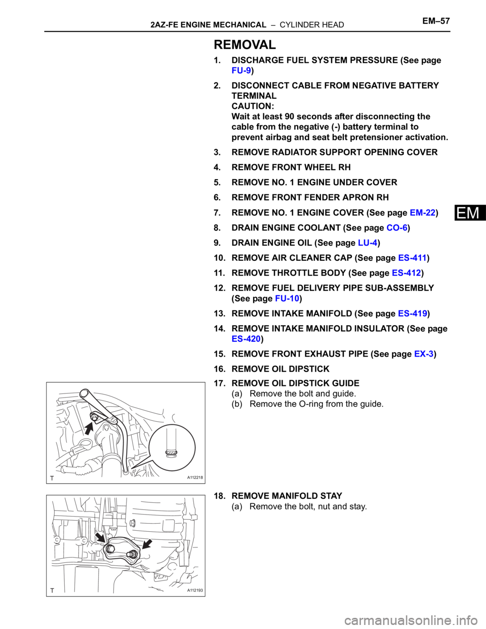
16. REMOVE OIL DIPSTICK
17. REMOVE OIL DIPSTICK GUIDE
(a) Remove the bolt and guide.
(b) Remove the O-ring from the guide.
18. REMOVE MANIFOLD STAY
(a) Remove the bolt, nut and stay.
A112218
A112193