2006 TOYOTA RAV4 refrigerant
[x] Cancel search: refrigerantPage 49 of 2000

ENGINE - 2AZ-FE ENGINE
01NEG09Y
01NEG10Y
Air
Conditioning
ECU
Engine Coolant
Temperature SensorFANL
ECM
FA N HCooling Fan
Relay No.3
Cooling Fan
Motor No.2
Cooling Fan
Relay No.1
Cooling Fan
Motor No.1
Low Speed (Series Connection)
High Speed (Parallel Connection) Air
Conditioning
ECU
Engine Coolant
Temperature SensorFA N L
ECM
FA N HCooling Fan
Relay No.3
Cooling Fan
Motor No.2
Cooling Fan
Relay No.1
Cooling Fan
Relay No.2
Cooling Fan
Motor No.1 : CAN
Cooling Fan
Relay No.2
EG-52
8. Cooling Fan Control
On the models with air conditioning, the ECM controls the operation of the cooling fan in two speeds (Low
and High) based on the engine coolant temperature sensor signal and the air conditioning ECU signal. This
control is accomplished by operating the 2 fan motors in 2 stages through low speed (series connection) and
high speed (parallel connection).
Wiring Diagram
Cooling Fan Operation
Air Conditioning ConditionEngine Coolant Temperature C (F)
A / C CompressorRefrigerant Pressure94 (201.2) or lower95.5 (203.9) or higher
OFF1.2 MPa (12.5 kgf / cm2, 178 psi) or lowerOFFHigh
ON1.2 MPa (12.5 kgf / cm2, 178 psi) or lowerLowHighON1.2 MPa (12.5 kgf / cm2, 178 psi) or higherHighHigh
Page 126 of 2000

ENGINE - 2GR-FE ENGINE
189EG14 189EG13
189EG16 189EG15
Fan
Speed
Engine Coolant TemperatureFan
Speed
Refrigerant Pressure
Fan
Speed
Engine SpeedFan
Speed
Vehicle Speed (A) Fan speed required by
engine coolant temperature(B) Fan speed required by
air conditioning
refrigerant pressure
(C) Fan speed required by
engine speed(D) Fan speed required by
vehicle speed EG-130
Operation
As illustrated below, the ECM determines the required fan speed by selecting the fastest fan speed from
among the following:
(A) Fan speed required by the engine coolant temperature
(B) Fan speed required by the air conditioning refrigerant pressure
(C) Fan speed required by the engine speed
(D) Fan speed required by the vehicle speed
Page 196 of 2000

2GR-FE ENGINE MECHANICAL – ENGINE ASSEMBLYEM–21
EM
REMOVAL
1. DISCHARGE REFRIGERANT FROM
REFRIGERATION SYSTEM (See page AC-172)
2. DISCHARGE FUEL SYSTEM PRESSURE (See page
FU-13)
3. DISCONNECT CABLE FROM NEGATIVE BATTERY
TERMINAL
CAUTION:
Wait at least 90 seconds after disconnecting the
cable from the negative (-) battery terminal to
prevent airbag and seat belt pretensioner activation.
4. REMOVE NO. 1 ENGINE UNDER COVER
(a) Remove the 4 bolts, 12 clips and under cover.
5. REMOVE REAR ENGINE UNDER COVER RH
(a) Remove the 2 clips and under cover.
6. REMOVE REAR ENGINE UNDER COVER LH
(a) Remove the 2 clips and under cover.
7. REMOVE NO. 2 ENGINE UNDER COVER
(a) Remove the 2 clips and under cover.
8. REMOVE FRONT FLOOR COVER (See page FU-34)
9. DRAIN ENGINE COOLANT (See page CO-8)
10. DRAIN ENGINE OIL (See page LU-4)
11. DRAIN AUTOMATIC TRANSAXLE FLUID
(a) 2WD:
Drain automatic transaxle fluid (see page AX-172).
(b) 4WD:
Drain automatic transaxle fluid (see page AX-173)
12. DRAIN TRANSFER OIL (for 4WD)
13. REMOVE HOOD SUB-ASSEMBLY (See page ED-4)
14. REMOVE V-BANK COVER SUB-ASSEMBLY
(a) Detach the 3 clips and remove the V-bank cover.
A137900
Page 687 of 2000
2GR-FE ENGINE MECHANICAL – ENGINE ASSEMBLYEM–41
EM
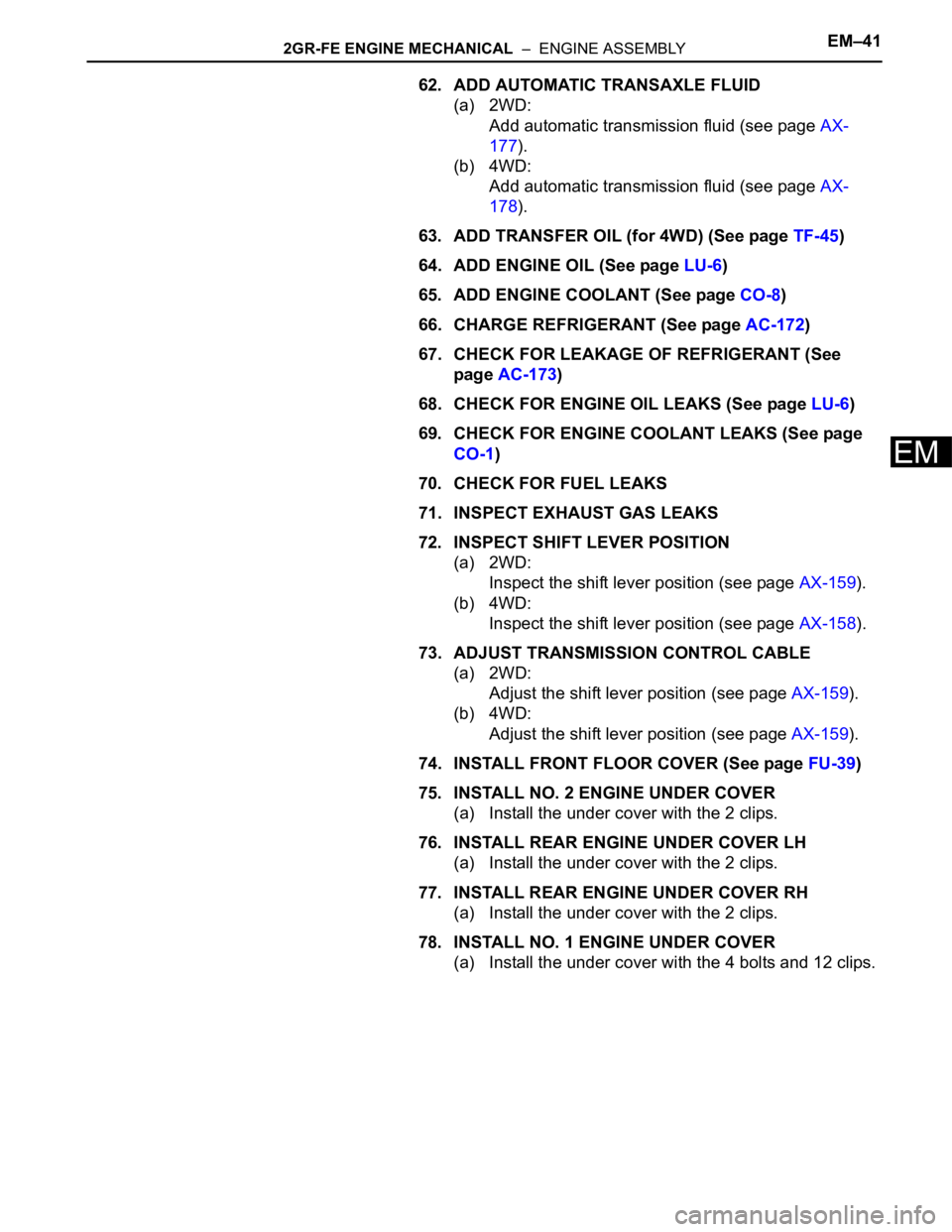
62. ADD AUTOMATIC TRANSAXLE FLUID
(a) 2WD:
Add automatic transmission fluid (see page AX-
177).
(b) 4WD:
Add automatic transmission fluid (see page AX-
178).
63. ADD TRANSFER OIL (for 4WD) (See page TF-45)
64. ADD ENGINE OIL (See page LU-6)
65. ADD ENGINE COOLANT (See page CO-8)
66. CHARGE REFRIGERANT (See page AC-172)
67. CHECK FOR LEAKAGE OF REFRIGERANT (See
page AC-173)
68. CHECK FOR ENGINE OIL LEAKS (See page LU-6)
69. CHECK FOR ENGINE COOLANT LEAKS (See page
CO-1)
70. CHECK FOR FUEL LEAKS
71. INSPECT EXHAUST GAS LEAKS
72. INSPECT SHIFT LEVER POSITION
(a) 2WD:
Inspect the shift lever position (see page AX-159).
(b) 4WD:
Inspect the shift lever position (see page AX-158).
73. ADJUST TRANSMISSION CONTROL CABLE
(a) 2WD:
Adjust the shift lever position (see page AX-159).
(b) 4WD:
Adjust the shift lever position (see page AX-159).
74. INSTALL FRONT FLOOR COVER (See page FU-39)
75. INSTALL NO. 2 ENGINE UNDER COVER
(a) Install the under cover with the 2 clips.
76. INSTALL REAR ENGINE UNDER COVER LH
(a) Install the under cover with the 2 clips.
77. INSTALL REAR ENGINE UNDER COVER RH
(a) Install the under cover with the 2 clips.
78. INSTALL NO. 1 ENGINE UNDER COVER
(a) Install the under cover with the 4 bolts and 12 clips.
Page 1650 of 2000
AC–22AIR CONDITIONING – AIR CONDITIONING SYSTEM (for Automatic Air Conditioning Sys-
tem)
AC
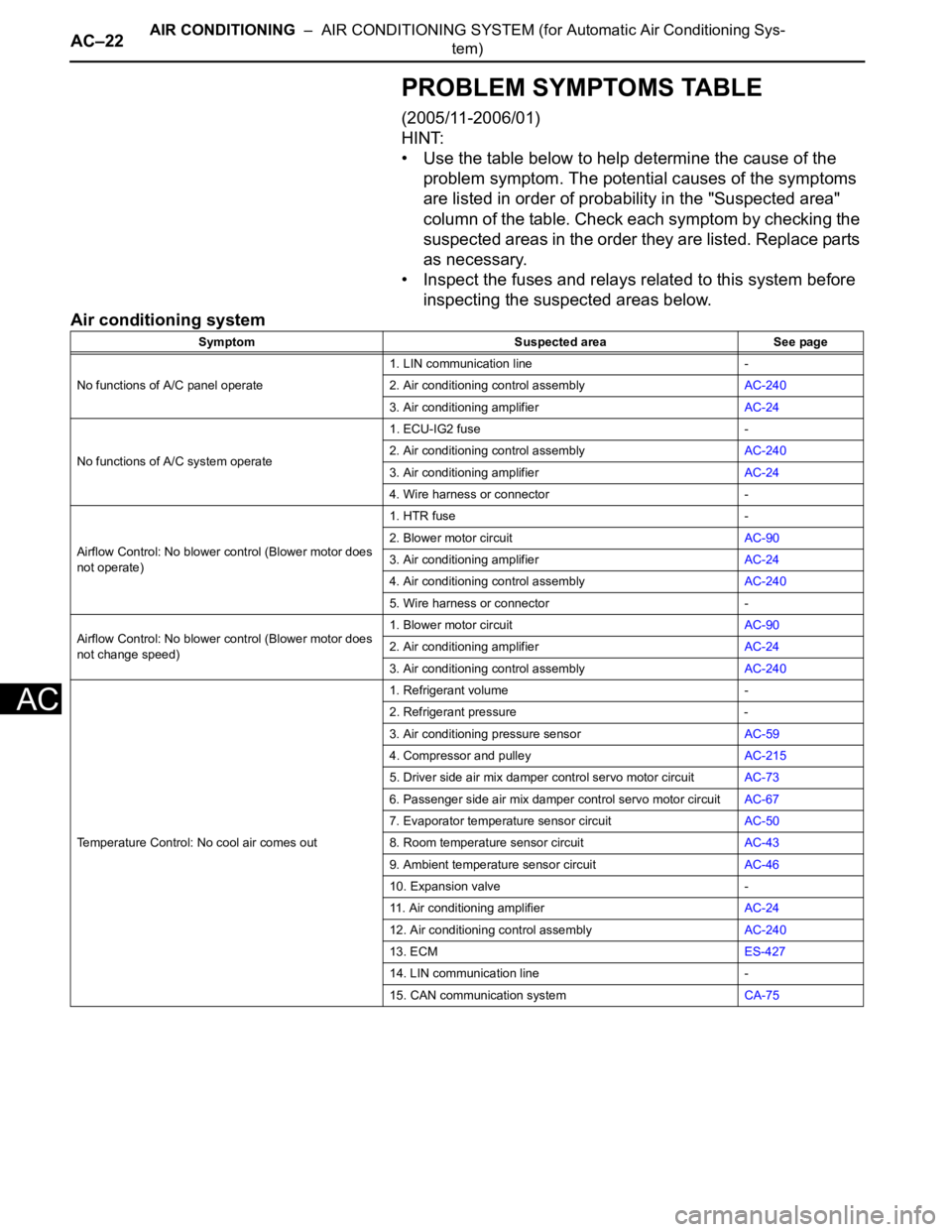
PROBLEM SYMPTOMS TABLE
(2005/11-2006/01)
HINT:
• Use the table below to help determine the cause of the
problem symptom. The potential causes of the symptoms
are listed in order of probability in the "Suspected area"
column of the table. Check each symptom by checking the
suspected areas in the order they are listed. Replace parts
as necessary.
• Inspect the fuses and relays related to this system before
inspecting the suspected areas below.
Air conditioning system
Symptom Suspected area See page
No functions of A/C panel operate1. LIN communication line -
2. Air conditioning control assemblyAC-240
3. Air conditioning amplifierAC-24
No functions of A/C system operate1. ECU-IG2 fuse -
2. Air conditioning control assemblyAC-240
3. Air conditioning amplifierAC-24
4. Wire harness or connector -
Airflow Control: No blower control (Blower motor does
not operate)1. HTR fuse -
2. Blower motor circuitAC-90
3. Air conditioning amplifierAC-24
4. Air conditioning control assemblyAC-240
5. Wire harness or connector -
Airflow Control: No blower control (Blower motor does
not change speed)1. Blower motor circuitAC-90
2. Air conditioning amplifierAC-24
3. Air conditioning control assemblyAC-240
Temperature Control: No cool air comes out1. Refrigerant volume -
2. Refrigerant pressure -
3. Air conditioning pressure sensorAC-59
4. Compressor and pulleyAC-215
5. Driver side air mix damper control servo motor circuitAC-73
6. Passenger side air mix damper control servo motor circuitAC-67
7. Evaporator temperature sensor circuitAC-50
8. Room temperature sensor circuitAC-43
9. Ambient temperature sensor circuitAC-46
10. Expansion valve -
11. Air conditioning amplifierAC-24
12. Air conditioning control assemblyAC-240
13. ECMES-427
14. LIN communication line -
15. CAN communication systemCA-75
Page 1652 of 2000
AC–24AIR CONDITIONING – AIR CONDITIONING SYSTEM (for Automatic Air Conditioning Sys-
tem)
AC
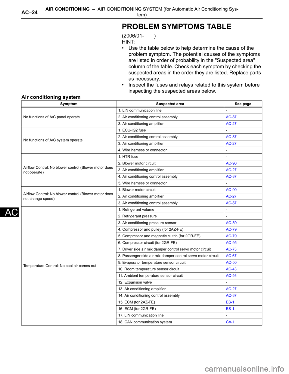
PROBLEM SYMPTOMS TABLE
(2006/01- )
HINT:
• Use the table below to help determine the cause of the
problem symptom. The potential causes of the symptoms
are listed in order of probability in the "Suspected area"
column of the table. Check each symptom by checking the
suspected areas in the order they are listed. Replace parts
as necessary.
• Inspect the fuses and relays related to this system before
inspecting the suspected areas below.
Air conditioning system
Symptom Suspected area See page
No functions of A/C panel operate1. LIN communication line -
2. Air conditioning control assemblyAC-87
3. Air conditioning amplifierAC-27
No functions of A/C system operate1. ECU-IG2 fuse -
2. Air conditioning control assemblyAC-87
3. Air conditioning amplifierAC-27
4. Wire harness or connector -
Airflow Control: No blower control (Blower motor does
not operate)1. HTR fuse -
2. Blower motor circuitAC-90
3. Air conditioning amplifierAC-27
4. Air conditioning control assemblyAC-87
5. Wire harness or connector -
Airflow Control: No blower control (Blower motor does
not change speed)1. Blower motor circuitAC-90
2. Air conditioning amplifierAC-27
3. Air conditioning control assemblyAC-87
Temperature Control: No cool air comes out1. Refrigerant volume -
2. Refrigerant pressure -
3. Air conditioning pressure sensorAC-59
4. Compressor and pulley (for 2AZ-FE)AC-79
5. Compressor and magnetic clutch (for 2GR-FE)AC-79
6. Compressor circuit (for 2GR-FE)AC-95
7. Driver side air mix damper control servo motor circuitAC-73
8. Passenger side air mix damper control servo motor circuitAC-67
9. Evaporator temperature sensor circuitAC-50
10. Room temperature sensor circuitAC-43
11. Ambient temperature sensor circuitAC-46
12. Expansion valve -
13. Air conditioning amplifierAC-27
14. Air conditioning control assemblyAC-87
15. ECM (for 2AZ-FE)ES-1
16. ECM (for 2GR-FE)ES-1
17. LIN communication line -
18. CAN communication systemCA-1
Page 1654 of 2000
AC–26AIR CONDITIONING – AIR CONDITIONING SYSTEM (for Automatic Air Conditioning Sys-
tem)
AC
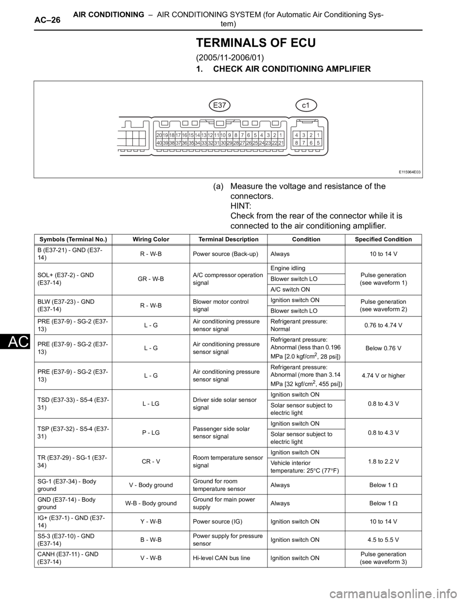
TERMINALS OF ECU
(2005/11-2006/01)
1. CHECK AIR CONDITIONING AMPLIFIER
(a) Measure the voltage and resistance of the
connectors.
HINT:
Check from the rear of the connector while it is
connected to the air conditioning amplifier.
E115964E03
Symbols (Terminal No.) Wiring Color Terminal Description ConditionSpecified Condition
B (E37-21) - GND (E37-
14)R - W-B Power source (Back-up) Always 10 to 14 V
SOL+ (E37-2) - GND
(E37-14)GR - W-BA/C compressor operation
signalEngine idling
Pulse generation
(see waveform 1) Blower switch LO
A/C switch ON
BLW (E37-23) - GND
(E37-14)R - W-BBlower motor control
signalIgnition switch ON
Pulse generation
(see waveform 2)
Blower switch LO
PRE (E37-9) - SG-2 (E37-
13)L - GAir conditioning pressure
sensor signalRefrigerant pressure:
Normal0.76 to 4.74 V
PRE (E37-9) - SG-2 (E37-
13)L - GAir conditioning pressure
sensor signalRefrigerant pressure:
Abnormal (less than 0.196
MPa [2.0 kgf/cm
2, 28 psi]) Below 0.76 V
PRE (E37-9) - SG-2 (E37-
13)L - GAir conditioning pressure
sensor signalRefrigerant pressure:
Abnormal (more than 3.14
MPa [32 kgf/cm
2, 455 psi])4.74 V or higher
TSD (E37-33) - S5-4 (E37-
31)L - LGDriver side solar sensor
signalIgnition switch ON
0.8 to 4.3 V
Solar sensor subject to
electric light
TSP (E37-32) - S5-4 (E37-
31)P - LGPassenger side solar
sensor signalIgnition switch ON
0.8 to 4.3 V
Solar sensor subject to
electric light
TR (E37-29) - SG-1 (E37-
34)CR - VRoom temperature sensor
signalIgnition switch ON
1.8 to 2.2 V
Vehicle interior
temperature: 25
C (77F)
SG-1 (E37-34) - Body
groundV - Body groundGround for room
temperature sensorAlways Below 1
GND (E37-14) - Body
groundW-B - Body groundGround for main power
supplyAlways Below 1
IG+ (E37-1) - GND (E37-
14)Y - W-B Power source (IG) Ignition switch ON 10 to 14 V
S5-3 (E37-10) - GND
(E37-14)B - W-BPower supply for pressure
sensorIgnition switch ON 4.5 to 5.5 V
CANH (E37-11) - GND
(E37-14)V - W-B Hi-level CAN bus line Ignition switch ONPulse generation
(see waveform 3)
Page 1657 of 2000
AIR CONDITIONING – AIR CONDITIONING SYSTEM (for Automatic Air Conditioning Sys-
tem)AC–29
AC
TERMINALS OF ECU
(2006/01- )
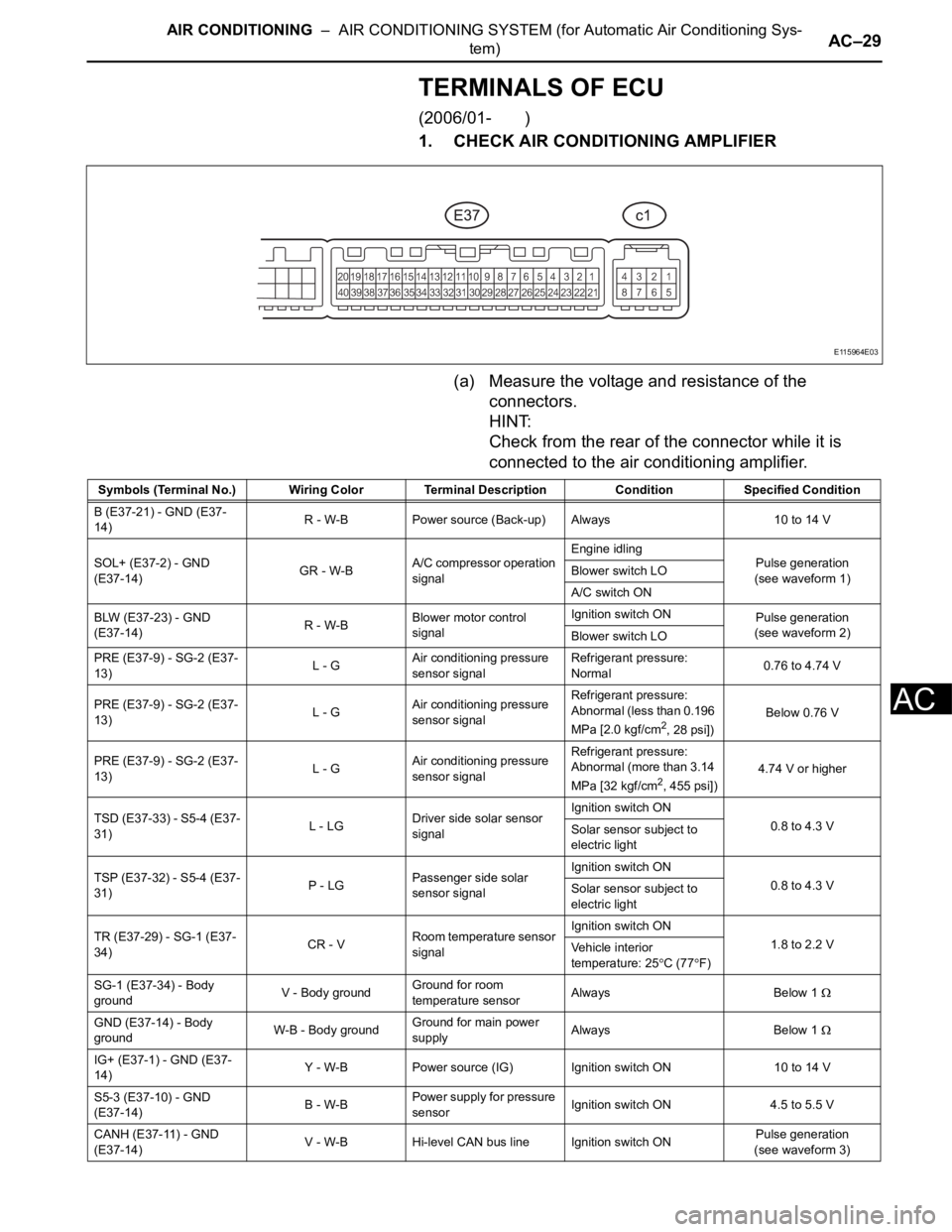
1. CHECK AIR CONDITIONING AMPLIFIER
(a) Measure the voltage and resistance of the
connectors.
HINT:
Check from the rear of the connector while it is
connected to the air conditioning amplifier.
E115964E03
Symbols (Terminal No.) Wiring Color Terminal Description ConditionSpecified Condition
B (E37-21) - GND (E37-
14)R - W-B Power source (Back-up) Always 10 to 14 V
SOL+ (E37-2) - GND
(E37-14)GR - W-BA/C compressor operation
signalEngine idling
Pulse generation
(see waveform 1) Blower switch LO
A/C switch ON
BLW (E37-23) - GND
(E37-14)R - W-BBlower motor control
signalIgnition switch ON
Pulse generation
(see waveform 2)
Blower switch LO
PRE (E37-9) - SG-2 (E37-
13)L - GAir conditioning pressure
sensor signalRefrigerant pressure:
Normal0.76 to 4.74 V
PRE (E37-9) - SG-2 (E37-
13)L - GAir conditioning pressure
sensor signalRefrigerant pressure:
Abnormal (less than 0.196
MPa [2.0 kgf/cm
2, 28 psi]) Below 0.76 V
PRE (E37-9) - SG-2 (E37-
13)L - GAir conditioning pressure
sensor signalRefrigerant pressure:
Abnormal (more than 3.14
MPa [32 kgf/cm
2, 455 psi])4.74 V or higher
TSD (E37-33) - S5-4 (E37-
31)L - LGDriver side solar sensor
signalIgnition switch ON
0.8 to 4.3 V
Solar sensor subject to
electric light
TSP (E37-32) - S5-4 (E37-
31)P - LGPassenger side solar
sensor signalIgnition switch ON
0.8 to 4.3 V
Solar sensor subject to
electric light
TR (E37-29) - SG-1 (E37-
34)CR - VRoom temperature sensor
signalIgnition switch ON
1.8 to 2.2 V
Vehicle interior
temperature: 25
C (77F)
SG-1 (E37-34) - Body
groundV - Body groundGround for room
temperature sensorAlways Below 1
GND (E37-14) - Body
groundW-B - Body groundGround for main power
supplyAlways Below 1
IG+ (E37-1) - GND (E37-
14)Y - W-B Power source (IG) Ignition switch ON 10 to 14 V
S5-3 (E37-10) - GND
(E37-14)B - W-BPower supply for pressure
sensorIgnition switch ON 4.5 to 5.5 V
CANH (E37-11) - GND
(E37-14)V - W-B Hi-level CAN bus line Ignition switch ONPulse generation
(see waveform 3)