2006 TOYOTA RAV4 brakes
[x] Cancel search: brakesPage 133 of 2000

CHASSIS - 4WD SYSTEM CH-66
4WD SYSTEM
DESCRIPTION
The 4WD system of the ’06 RAV4 uses an active torque control 4WD system.
It is a compact, lightweight, and high performance 4WD system that optimally controls the torque
distribution to the front and rear wheels through the electric control coupling in the rear differential.
ACTIVE TORQUE CONTROL 4WD SYSTEM
1. General
Based on information provided by various sensors, the 4WD ECU controls the amperage that is applied
to the electric control coupling, in order to transmit drive torque to the rear wheels when needed, and in
the amount needed. The following describes the features of the active torque control 4WD system.
Traction performance
Realizes stable start-off and acceleration performance
Driving stability performanceRealizes stable cornering performance
Fuel economyRealizes better fuel economy by transmitting drive torque to the rear
wheels when needed, in the amount needed.
A four-wheel drive lock switch has been provided. This enables the driver to select between the AUTO
and LOCK modes by operating the switch. The system optimally controls the torque distribution to the
front and rear wheels in the respective modes.
Mode
Four-wheel Drive
Lock Switch and
Indicator Light
Outline
AUTOOFF
Optimally distributes drive torque to the front and rear wheels.
Ensures optimal start-off performance during a start-off, based on
information provided by various sensors.
Suppresses the tight corner braking phenomenon* during low-speed
cornering.
Reduces the amount of torque distribution to the rear wheels and
improves fuel economy when the system judges that the vehicle is
traveling steadily.
Disengages the 4WD during braking deceleration.
LOCKON
Distributes the maximum torque limit to the rear wheels.
Distributes the maximum torque limit to the rear wheels during
start-off.
Distributes optimal torque during low-speed cornering.
Disengages the 4WD during braking deceleration.
Disengages the LOCK mode and transfers to the AUTO mode when
the vehicle speed exceeds 40 km / h (25 mph).
*: Tight corner braking phenomenon: a condition in which the brakes are applied due to a rotational difference
between the front and rear wheels, such as during low-speed cornering in the 4WD mode.
The 4WD ECU effects cooperative control with the skid control ECU, in order to control the drive torque
distribution to the front and rear wheels in accordance with information received from the skid control
ECU. These controls ensure a smooth acceleration and driving stability.
Page 395 of 2000

SERVICE SPECIFICATIONS – BRAKESS–83
SS
TORQUE SPECIFICATIONS
Brake Pedal
Brake Master Cylinder
Brake Booster
Front Brake
Front Brake Flexible Hose
Rear Brake
Rear Brake Flexible Hose
Part tightened N*m kgf*cm ft.*lbf
Brake pedal support x Body 12.7 130 9
Brake pedal support x Instrument
panel reinforcement25 255 18
Stop light switch 1.5 or less 15 or less 13 in.*lbf or less
Part tightened N*m kgf*cm ft.*lbf
Brake master cylinder x Brake
booster12.5 127 9
Brake master cylinder x Brake
tube (without SST)15.2 155 11
Brake master cylinder x Brake
tube (with SST)14 144 10
Part tightened N*m kgf*cm ft.*lbf
Brake booster x Brake pedal
support12.7 130 9
Push rod clevis lock nut 26 265 19
Part tightened N*m kgf*cm ft.*lbf
Bleeder plug 8.3 85 73 in.*lbf
Cylinder mounting x Knuckle 98 999 72
Cylinder x Cylinder mounting 34.3 350 25
Flexible hose x Cylinder 29.4 300 22
Part tightened N*m kgf*cm ft.*lbf
Flexible hose x Brake cylinder 29.4 300 22
Flexible hose clamp bolt 18.5 189 14
Flexible hose x Brake tube
(without SST)15.2 155 11
Flexible hose x Brake tube (with
SST)14 144 10
Part tightened N*m kgf*cm ft.*lbf
Bleeder plug 8.3 85 73 in.*lbf
Cylinder mounting x Carrier 88 897 65
Cylinder x Cylinder mounting 26.5 270 20
Flexible hose x Cylinder 30.4 310 22
Part tightened N*m kgf*cm ft.*lbf
Flexible hose x Brake cylinder 30.4 310 22
Flexible hose x Brake tube
(without SST)15.2 155 11
Flexible hose x Brake tube (with
SST)14 144 10
Page 404 of 2000

AXLE – FRONT AXLE HUBAH–7
AH
REMOVAL
(2005/11-2006/01)
HINT:
• Use the same procedures for the RH side and LH side.
• The procedures listed below are for the LH side.
1. REMOVE FRONT WHEEL
2. DRAIN AUTOMATIC TRANSAXLE FLUID
(a) Drain the automatic transaxle fluid for U140F (see
page AX-147).
(b) Drain the automatic transaxle fluid for U241E (see
page AX-146).
3. DISCONNECT CABLE FROM NEGATIVE BATTERY
TERMINAL
CAUTION:
Wait at least 90 seconds after disconnecting the
cable from the negative (-) battery terminal to
prevent airbag and seat belt pretensioner activation.
4. REMOVE FRONT AXLE HUB NUT
(a) Using SST and a hammer, unstake the staked part
of the nut.
SST 09930-00010
NOTICE:
Loosen the staked part of the nut completely,
otherwise the screw of the drive shaft may be
damaged.
(b) While applying the brakes, remove the lock axle hub
nut.
5. REMOVE FRONT SPEED SENSOR LH (See page BC-
191)
6. REMOVE FRONT DISC BRAKE CYLINDER
ASSEMBLY LH (See page BR-40)
7. REMOVE FRONT DISC (See page BR-42)
8. DISCONNECT TIE ROD END SUB-ASSEMBLY LH
(See page PS-42)
9. DISCONNECT FRONT SUSPENSION NO. 1 LOWER
ARM SUB-ASSEMBLY LH
(a) Remove the bolt and 2 nuts.
(b) Disconnect the lower arm from the ball joint.
C129483E01
C127531
Page 416 of 2000
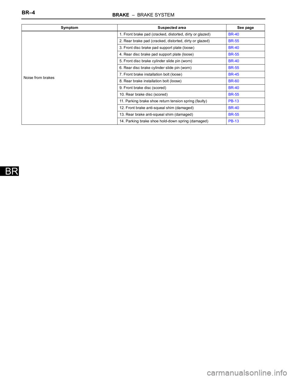
BR–4BRAKE – BRAKE SYSTEM
BR
Noise from brakes1. Front brake pad (cracked, distorted, dirty or glazed)BR-40
2. Rear brake pad (cracked, distorted, dirty or glazed)BR-55
3. Front disc brake pad support plate (loose)BR-40
4. Rear disc brake pad support plate (loose)BR-55
5. Front disc brake cylinder slide pin (worn)BR-40
6. Rear disc brake cylinder slide pin (worn)BR-55
7. Front brake installation bolt (loose)BR-45
8. Rear brake installation bolt (loose)BR-60
9. Front brake disc (scored)BR-40
10. Rear brake disc (scored)BR-55
11. Parking brake shoe return tension spring (faulty)PB-13
12. Front brake anti-squeal shim (damaged)BR-40
13. Rear brake anti-squeal shim (damaged)BR-55
14. Parking brake shoe hold-down spring (damaged)PB-13 Symptom Suspected area See page
Page 1343 of 2000
GF1A TRANSFER – ACTIVE TORQUE CONTROL 4WD SYSTEMTF–15
TF
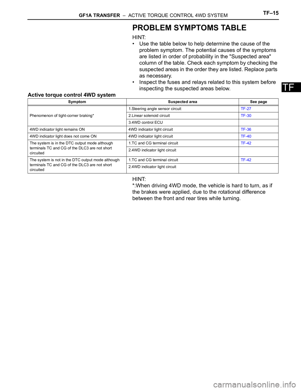
PROBLEM SYMPTOMS TABLE
HINT:
• Use the table below to help determine the cause of the
problem symptom. The potential causes of the symptoms
are listed in order of probability in the "Suspected area"
column of the table. Check each symptom by checking the
suspected areas in the order they are listed. Replace parts
as necessary.
• Inspect the fuses and relays related to this system before
inspecting the suspected areas below.
Active torque control 4WD system
HINT:
*:When driving 4WD mode, the vehicle is hard to turn, as if
the brakes were applied, due to the rotational difference
between the front and rear tires while turning.
Symptom Suspected area See page
Phenomenon of tight-corner braking*1.Steering angle sensor circuitTF-27
2.Linear solenoid circuitTF-30
3.4WD control ECU
4WD indicator light remains ON 4WD indicator light circuitTF-36
4WD indicator light does not come ON 4WD indicator light circuitTF-40
The system is in the DTC output mode although
terminals TC and CG of the DLC3 are not short
circuited1.TC and CG terminal circuitTF-42
2.4WD indicator light circuit
The system is not in the DTC output mode although
terminals TC and CG of the DLC3 are not short
circuited1.TC and CG terminal circuitTF-42
2.4WD indicator light circuit
Page 1450 of 2000
AXLE – FRONT AXLE HUBAH–9
AH
REMOVAL
(2006/01- )
HINT:
• Use the same procedures for the RH side and LH side.
• The procedures listed below are the LH side.
1. REMOVE FRONT WHEEL
2. DRAIN AUTOMATIC TRANSAXLE FLUID
(a) Drain the automatic transaxle fluid for U140F (see
page AX-147).
(b) Drain the automatic transaxle fluid for U241E (see
page AX-146).
(c) Drain the automatic transaxle fluid for U151E (see
page AX-172).
(d) Drain the automatic transaxle fluid for U151F (see
page AX-173).
3. DISCONNECT CABLE FROM NEGATIVE BATTERY
TERMINAL
CAUTION:
Wait at least 90 seconds after disconnecting the
cable from the negative (-) battery terminal to
prevent airbag and seat belt pretensioner activation.
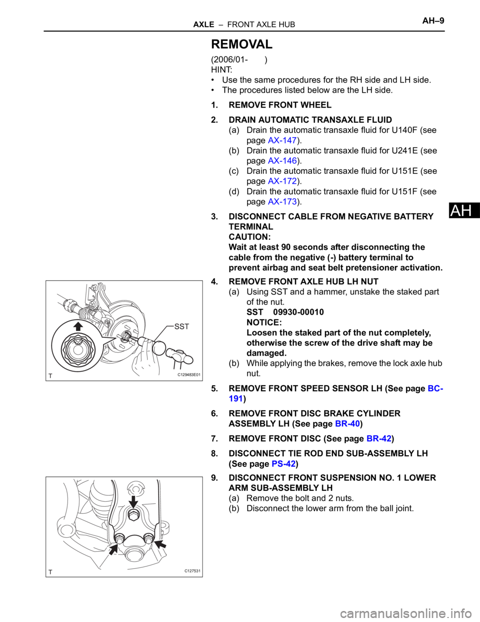
4. REMOVE FRONT AXLE HUB LH NUT
(a) Using SST and a hammer, unstake the staked part
of the nut.
SST 09930-00010
NOTICE:
Loosen the staked part of the nut completely,
otherwise the screw of the drive shaft may be
damaged.
(b) While applying the brakes, remove the lock axle hub
nut.
5. REMOVE FRONT SPEED SENSOR LH (See page BC-
191)
6. REMOVE FRONT DISC BRAKE CYLINDER
ASSEMBLY LH (See page BR-40)
7. REMOVE FRONT DISC (See page BR-42)
8. DISCONNECT TIE ROD END SUB-ASSEMBLY LH
(See page PS-42)
9. DISCONNECT FRONT SUSPENSION NO. 1 LOWER
ARM SUB-ASSEMBLY LH
(a) Remove the bolt and 2 nuts.
(b) Disconnect the lower arm from the ball joint.
C129483E01
C127531
Page 1509 of 2000
BC–6BRAKE CONTROL – VEHICLE STABILITY CONTROL SYSTEM
BC
SYSTEM DESCRIPTION
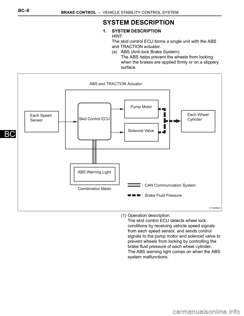
1. SYSTEM DESCRIPTION
HINT:
The skid control ECU forms a single unit with the ABS
and TRACTION actuator.
(a) ABS (Anti-lock Brake System):
The ABS helps prevent the wheels from locking
when the brakes are applied firmly or on a slippery
surface.
(1) Operation description:
The skid control ECU detects wheel lock
conditions by receiving vehicle speed signals
from each speed sensor, and sends control
signals to the pump motor and solenoid valve to
prevent wheels from locking by controlling the
brake fluid pressure of each wheel cylinder.
The ABS warning light comes on when the ABS
system malfunctions.
C115099E04
Page 1510 of 2000
BRAKE CONTROL – VEHICLE STABILITY CONTROL SYSTEMBC–7
BC
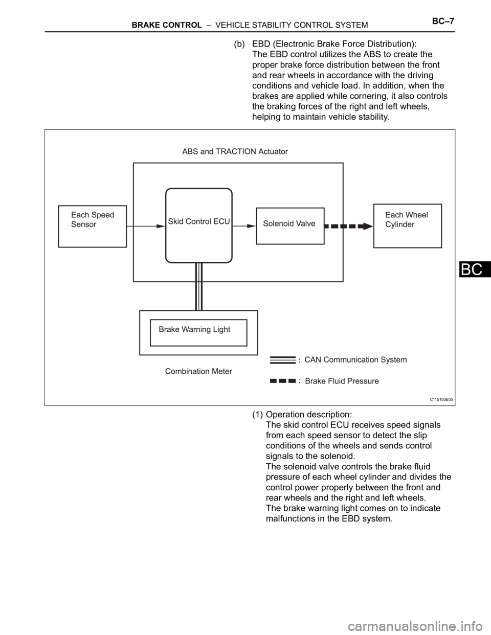
(b) EBD (Electronic Brake Force Distribution):
The EBD control utilizes the ABS to create the
proper brake force distribution between the front
and rear wheels in accordance with the driving
conditions and vehicle load. In addition, when the
brakes are applied while cornering, it also controls
the braking forces of the right and left wheels,
helping to maintain vehicle stability.
(1) Operation description:
The skid control ECU receives speed signals
from each speed sensor to detect the slip
conditions of the wheels and sends control
signals to the solenoid.
The solenoid valve controls the brake fluid
pressure of each wheel cylinder and divides the
control power properly between the front and
rear wheels and the right and left wheels.
The brake warning light comes on to indicate
malfunctions in the EBD system.
C115100E05