Page 81 of 2000
ENGINE - 2GR-FE ENGINE
285EG77
Main Oil Hole
Cylinder Head
(for Left Bank)
Oil
Filter
Exhaust
Camshaft
Timing OCV*
Intake
Camshaft
Timing OCV*
Oil
PumpExhaust
VVT-i
Controller
Intake
VVT-i
Controller
Relief
Va l v e
Cylinder Head
(for Right Bank)
Exhaust
Camshaft
Timing OCV*
Intake
Camshaft
Timing OCV*
Exhaust
VVT-i
Controller
Intake
VVT-i
Controller
Secondary
Chain
TensionerPrimary
Chain
Tensioner
Secondary
Chain
Tensioner
Cylinder
Block
Crankshaft
Journal
Crankshaft
Pins
Connecting
Rods
Cylinder Head
(for Left Bank)
Oil
Jets
Intake
Camshaft
Journal
Exhaust
Camshaft
Journal
Lash
Adjuster
Cylinder Head
(for Right Bank)
Intake
Camshaft
Journal
Exhaust
Camshaft
Journal
Lash
Adjuster
Oil PanEG-85
Oil Circuit
*: Oil Control Valve
Page 1946 of 2000

ES–582AZ-FE ENGINE CONTROL SYSTEM – SFI SYSTEM
ES
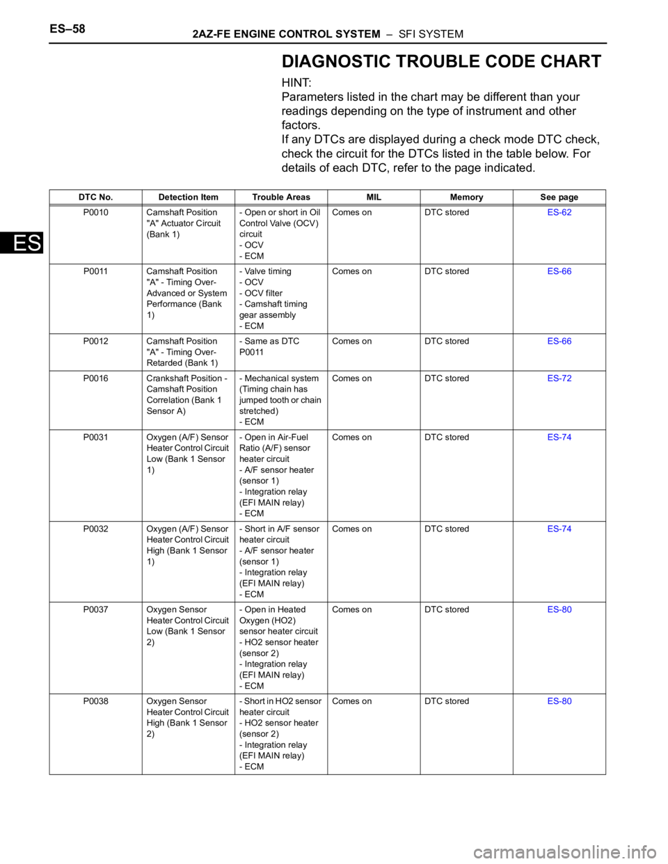
DIAGNOSTIC TROUBLE CODE CHART
HINT:
Parameters listed in the chart may be different than your
readings depending on the type of instrument and other
factors.
If any DTCs are displayed during a check mode DTC check,
check the circuit for the DTCs listed in the table below. For
details of each DTC, refer to the page indicated.
DTC No. Detection Item Trouble Areas MIL Memory See page
P0010 Camshaft Position
"A" Actuator Circuit
(Bank 1)- Open or short in Oil
Control Valve (OCV)
circuit
- OCV
- ECMComes on DTC storedES-62
P0011 Camshaft Position
"A" - Timing Over-
Advanced or System
Performance (Bank
1)- Valve timing
- OCV
- OCV filter
- Camshaft timing
gear assembly
- ECMComes on DTC storedES-66
P0012 Camshaft Position
"A" - Timing Over-
Retarded (Bank 1)- Same as DTC
P0011Comes on DTC storedES-66
P0016 Crankshaft Position -
Camshaft Position
Correlation (Bank 1
Sensor A)- Mechanical system
(Timing chain has
jumped tooth or chain
stretched)
- ECMComes on DTC storedES-72
P0031 Oxygen (A/F) Sensor
Heater Control Circuit
Low (Bank 1 Sensor
1)- Open in Air-Fuel
Ratio (A/F) sensor
heater circuit
- A/F sensor heater
(sensor 1)
- Integration relay
(EFI MAIN relay)
- ECMComes on DTC storedES-74
P0032 Oxygen (A/F) Sensor
Heater Control Circuit
High (Bank 1 Sensor
1)- Short in A/F sensor
heater circuit
- A/F sensor heater
(sensor 1)
- Integration relay
(EFI MAIN relay)
- ECMComes on DTC storedES-74
P0037 Oxygen Sensor
Heater Control Circuit
Low (Bank 1 Sensor
2)- Open in Heated
Oxygen (HO2)
sensor heater circuit
- HO2 sensor heater
(sensor 2)
- Integration relay
(EFI MAIN relay)
- ECMComes on DTC storedES-80
P0038 Oxygen Sensor
Heater Control Circuit
High (Bank 1 Sensor
2)- Short in HO2 sensor
heater circuit
- HO2 sensor heater
(sensor 2)
- Integration relay
(EFI MAIN relay)
- ECMComes on DTC storedES-80
Page 1962 of 2000

ES–742AZ-FE ENGINE CONTROL SYSTEM – SFI SYSTEM
ES
MONITOR DESCRIPTION
The ECM optimizes the intake valve timing using the VVT (Variable Valve Timing) system to control the
intake camshaft. The VVT system includes the ECM, the Oil Control Valve (OCV) and the VVT controller.
The ECM sends a target duty-cycle control signal to the OCV. This control signal regulates the oil
pressure supplied to the VVT controller. The VVT controller can advance or retard the intake camshaft.
If the difference between the target and actual intake valve timings is large, and changes in the actual
intake valve timing are small, the ECM interprets this as the VVT controller stuck malfunction and sets a
DTC.
Example:
A DTC is set when the following conditions 1, 2 and 3 are met:
1. The difference between the target and actual intake valve timing is more than 5
CA (Crankshaft
Angle) and the condition continues for more than 4.5 seconds.
2. It takes 5 seconds or more to change the valve timing by 5
CA.
3. After above conditions 1 and 2 are met, the OCV is forcibly activated 63 times or more.
DTC P0011 (Advanced Cam Timing) is subject to 1 trip detection logic.
DTC P0012 (Retarded Cam Timing) is subject to 2 trip detection logic.
These DTCs indicate that the VVT controller cannot operate properly due to OCV malfunctions or the
presence of foreign objects in the OCV.
The monitor will run if all of the following conditions are met:
– The engine is warm (the engine coolant temperature is 75
C [167F] or more).
– The vehicle has been driven at more than 64 km/h (40 mph) for 3 minutes.
– The engine has idled for 3 minutes.
MONITOR STRATEGY
DTC No. DTC Detection Conditions Trouble Areas
P0011Advanced camshaft timing:
With warm engine and engine speed of between 550 rpm and
4,000 rpm, all conditions (1), (2) and (3) met (1 trip detection
logic):
1. Difference between target and actual intake valve timings
more than 5
CA (Crankshaft Angle) for 4.5 seconds
2. Current intake valve timing fixed (timing changes less than
5
CA in 5 seconds)
3. Variations in VVT controller timing more than 19
CA of
maximum delayed timing (malfunction in advance timing)• Valve timing
•OCV
• OCV filter
• Camshaft timing gear assembly
•ECM
P0012Retarded camshaft timing:
With warm engine and engine speed of between 550 rpm and
4,000 rpm, all conditions (1), (2) and (3) met (2 trip detection
logic):
1. Difference between target and actual intake valve timings
more than 5
CA (Crankshaft Angle) for 4.5 seconds
2. Current intake valve timing fixed (timing changes less than
5
CA in 5 seconds)
3. Variations in VVT controller timing 19CA or less of
maximum delayed timing (malfunction in retarded timing)• Valve timing
•OCV
• OCV filter
• Camshaft timing gear assembly
•ECM
Related DTCsP0011: Advanced camshaft timing
P0012: Retarded camshaft timing
Required Sensors/Components (Main) VVT OCV and VVT Actuator
Required Sensors/Components (Related)Crankshaft position sensor, camshaft position sensor and Engine
coolant temperature sensor
Frequency of Operation Once per driving cycle
Duration Within 10 seconds
MIL OperationAdvanced camshaft timing: Immediate
Retarded camshaft timing: 2 driving cycles
Sequence of Operation None
Page 1965 of 2000

2AZ-FE ENGINE CONTROL SYSTEM – SFI SYSTEMES–77
ES
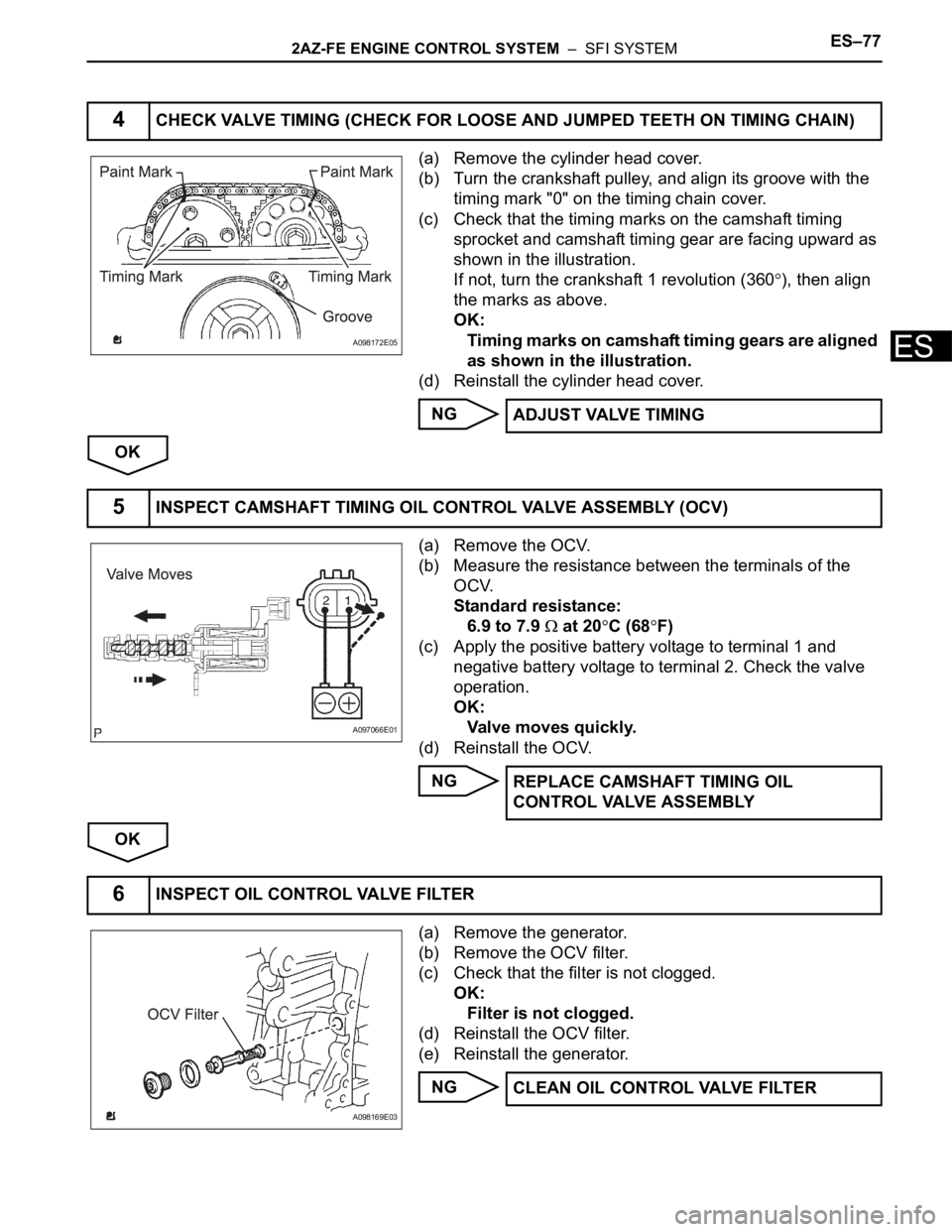
(a) Remove the cylinder head cover.
(b) Turn the crankshaft pulley, and align its groove with the
timing mark "0" on the timing chain cover.
(c) Check that the timing marks on the camshaft timing
sprocket and camshaft timing gear are facing upward as
shown in the illustration.
If not, turn the crankshaft 1 revolution (360
), then align
the marks as above.
OK:
Timing marks on camshaft timing gears are aligned
as shown in the illustration.
(d) Reinstall the cylinder head cover.
NG
OK
(a) Remove the OCV.
(b) Measure the resistance between the terminals of the
OCV.
Standard resistance:
6.9 to 7.9
at 20C (68F)
(c) Apply the positive battery voltage to terminal 1 and
negative battery voltage to terminal 2. Check the valve
operation.
OK:
Valve moves quickly.
(d) Reinstall the OCV.
NG
OK
(a) Remove the generator.
(b) Remove the OCV filter.
(c) Check that the filter is not clogged.
OK:
Filter is not clogged.
(d) Reinstall the OCV filter.
(e) Reinstall the generator.
NG
4CHECK VALVE TIMING (CHECK FOR LOOSE AND JUMPED TEETH ON TIMING CHAIN)
A098172E05
ADJUST VALVE TIMING
5INSPECT CAMSHAFT TIMING OIL CONTROL VALVE ASSEMBLY (OCV)
A097066E01
REPLACE CAMSHAFT TIMING OIL
CONTROL VALVE ASSEMBLY
6INSPECT OIL CONTROL VALVE FILTER
A098169E03
CLEAN OIL CONTROL VALVE FILTER