2006 TOYOTA RAV4 Brake booster
[x] Cancel search: Brake boosterPage 395 of 2000

SERVICE SPECIFICATIONS – BRAKESS–83
SS
TORQUE SPECIFICATIONS
Brake Pedal
Brake Master Cylinder
Brake Booster
Front Brake
Front Brake Flexible Hose
Rear Brake
Rear Brake Flexible Hose
Part tightened N*m kgf*cm ft.*lbf
Brake pedal support x Body 12.7 130 9
Brake pedal support x Instrument
panel reinforcement25 255 18
Stop light switch 1.5 or less 15 or less 13 in.*lbf or less
Part tightened N*m kgf*cm ft.*lbf
Brake master cylinder x Brake
booster12.5 127 9
Brake master cylinder x Brake
tube (without SST)15.2 155 11
Brake master cylinder x Brake
tube (with SST)14 144 10
Part tightened N*m kgf*cm ft.*lbf
Brake booster x Brake pedal
support12.7 130 9
Push rod clevis lock nut 26 265 19
Part tightened N*m kgf*cm ft.*lbf
Bleeder plug 8.3 85 73 in.*lbf
Cylinder mounting x Knuckle 98 999 72
Cylinder x Cylinder mounting 34.3 350 25
Flexible hose x Cylinder 29.4 300 22
Part tightened N*m kgf*cm ft.*lbf
Flexible hose x Brake cylinder 29.4 300 22
Flexible hose clamp bolt 18.5 189 14
Flexible hose x Brake tube
(without SST)15.2 155 11
Flexible hose x Brake tube (with
SST)14 144 10
Part tightened N*m kgf*cm ft.*lbf
Bleeder plug 8.3 85 73 in.*lbf
Cylinder mounting x Carrier 88 897 65
Cylinder x Cylinder mounting 26.5 270 20
Flexible hose x Cylinder 30.4 310 22
Part tightened N*m kgf*cm ft.*lbf
Flexible hose x Brake cylinder 30.4 310 22
Flexible hose x Brake tube
(without SST)15.2 155 11
Flexible hose x Brake tube (with
SST)14 144 10
Page 415 of 2000
BRAKE – BRAKE SYSTEMBR–3
BR
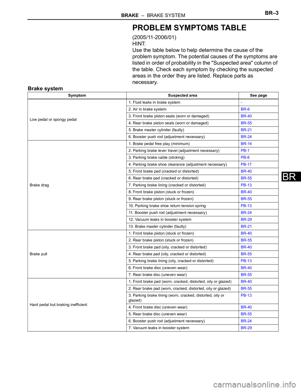
PROBLEM SYMPTOMS TABLE
(2005/11-2006/01)
HINT:
Use the table below to help determine the cause of the
problem symptom. The potential causes of the symptoms are
listed in order of probability in the "Suspected area" column of
the table. Check each symptom by checking the suspected
areas in the order they are listed. Replace parts as
necessary.
Brake system
Symptom Suspected area See page
Low pedal or spongy pedal1. Fluid leaks in brake system -
2. Air in brake systemBR-6
3. Front brake piston seals (worn or damaged)BR-40
4. Rear brake piston seals (worn or damaged)BR-55
5. Brake master cylinder (faulty)BR-21
6. Booster push rod (adjustment necessary)BR-24
Brake drag1. Brake pedal free play (minimum)BR-14
2. Parking brake lever travel (adjustment necessary)PB-1
3. Parking brake cable (sticking)PB-8
4. Parking brake shoe clearance (adjustment necessary)PB-17
5. Front brake pad (cracked or distorted)BR-40
6. Rear brake pad (cracked or distorted)BR-55
7. Parking brake lining (cracked or distorted)PB-13
8. Front brake piston (stuck or frozen)BR-40
9. Rear brake piston (stuck or frozen)BR-55
10. Parking brake shoe return tension springPB-13
11. Booster push rod (adjustment necessary)BR-24
12. Vacuum leaks in booster systemBR-29
13. Brake master cylinder (faulty)BR-21
Brake pull1. Front brake piston (stuck or frozen)BR-40
2. Rear brake piston (stuck or frozen)BR-55
3. Front brake pad (oily, cracked or distorted)BR-40
4. Rear brake pad (oily, cracked or distorted)BR-55
5. Parking brake lining (oily, cracked or distorted)PB-13
6. Front brake disc (uneven wear)BR-40
7. Rear brake disc (uneven wear)BR-55
Hard pedal but braking inefficient1. Front brake pad (worn, cracked, distorted, oily or glazed)BR-40
2. Rear brake pad (worn, cracked, distorted, oily or glazed)BR-55
3. Parking brake lining (worn, cracked, distorted, oily or
glazed)PB-13
4. Front brake disc (uneven wear)BR-40
5. Rear brake disc (uneven wear)BR-55
6. Booster push rod (adjustment necessary)BR-24
7. Vacuum leaks in booster systemBR-29
Page 1534 of 2000
BRAKE CONTROL – VEHICLE STABILITY CONTROL SYSTEMBC–31
BC
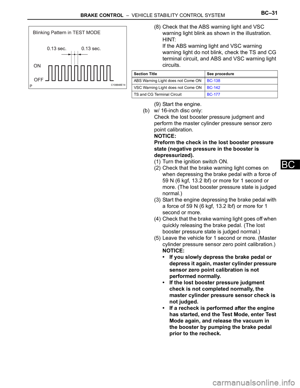
(8) Check that the ABS warning light and VSC
warning light blink as shown in the illustration.
HINT:
If the ABS warning light and VSC warning
warning light do not blink, check the TS and CG
terminal circuit, and ABS and VSC warning light
circuits.
(9) Start the engine.
(b) w/ 16-inch disc only:
Check the lost booster pressure judgment and
perform the master cylinder pressure sensor zero
point calibration.
NOTICE:
Preform the check in the lost booster pressure
state (negative pressure in the booster is
depressurized).
(1) Turn the ignition switch ON.
(2) Check that the brake warning light comes on
when depressing the brake pedal with a force of
59 N (6 kgf, 13.2 lbf) or more for 1 second or
more. (The lost booster pressure state is judged
normal.)
(3) Start the engine depressing the brake pedal with
a force of 59 N (6 kgf, 13.2 lbf) or more for 1
second or more.
(4) Check that the brake warning light goes off when
quickly releasing the brake pedal. (The lost
booster pressure state is judged normal.)
(5) Leave the vehicle for 1 second or more. (Master
cylinder pressure sensor zero point calibration.)
NOTICE:
• If you slowly depress the brake pedal or
depress it again, master cylinder pressure
sensor zero point calibration is not
performed normally.
• If the lost booster pressure judgment
check is not completed normally, the
master cylinder pressure sensor check is
not judged.
• If a recheck is performed after the engine
has started, end the Test Mode, enter Test
Mode again, and release the vacuum in
the booster by pumping the brake pedal
prior to the recheck.
C108848E14
Section Title See procedure
ABS Warning Light does not Come ONBC-138
VSC Warning Light does not Come ONBC-142
TS and CG Terminal CircuitBC-177
Page 1538 of 2000
BRAKE CONTROL – VEHICLE STABILITY CONTROL SYSTEMBC–35
BC
HINT:
See the list of the DTCs (refer to "DTC OF TEST
MODE FUNCTION (SIGNAL CHECK)" below).
2. CHECK SENSOR SIGNAL BY TEST MODE (When not
Using Intelligent Tester)
(a) Procedures for test mode:
(1) Turn the ignition switch OFF.
(2) Check that the steering wheel is in the centered
position.
(3) Check that the shift lever is in the P position and
apply the parking brake.
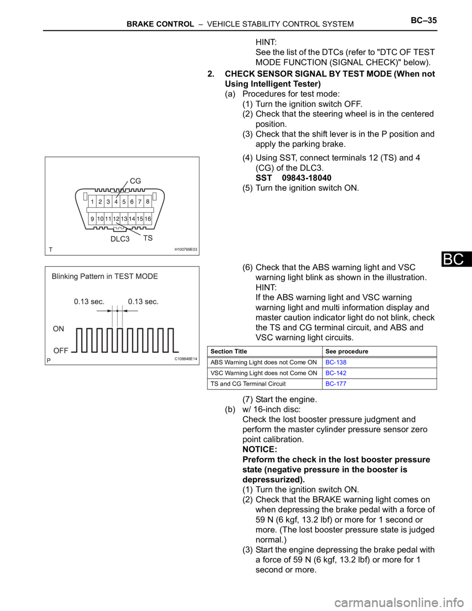
(4) Using SST, connect terminals 12 (TS) and 4
(CG) of the DLC3.
SST 09843-18040
(5) Turn the ignition switch ON.
(6) Check that the ABS warning light and VSC
warning light blink as shown in the illustration.
HINT:
If the ABS warning light and VSC warning
warning light and multi information display and
master caution indicator light do not blink, check
the TS and CG terminal circuit, and ABS and
VSC warning light circuits.
(7) Start the engine.
(b) w/ 16-inch disc:
Check the lost booster pressure judgment and
perform the master cylinder pressure sensor zero
point calibration.
NOTICE:
Preform the check in the lost booster pressure
state (negative pressure in the booster is
depressurized).
(1) Turn the ignition switch ON.
(2) Check that the BRAKE warning light comes on
when depressing the brake pedal with a force of
59 N (6 kgf, 13.2 lbf) or more for 1 second or
more. (The lost booster pressure state is judged
normal.)
(3) Start the engine depressing the brake pedal with
a force of 59 N (6 kgf, 13.2 lbf) or more for 1
second or more.
H100769E03
C108848E14Section Title See procedure
ABS Warning Light does not Come ONBC-138
VSC Warning Light does not Come ONBC-142
TS and CG Terminal CircuitBC-177
Page 1539 of 2000
BC–36BRAKE CONTROL – VEHICLE STABILITY CONTROL SYSTEM
BC
(4) Check that the brake warning light goes off when
quickly releasing the brake pedal. (The lost
booster pressure state is judged normal.)
(5) Leave the vehicle for 1 second or more. (Master
cylinder pressure sensor zero point calibration.)
NOTICE:
• If you slowly depress the brake pedal or
depress it again, master cylinder pressure
sensor zero point calibration is not
performed normally.
• If the lost booster pressure judgment
check is not completed normally, the
master cylinder pressure sensor check is
not judged.
• If a recheck is performed after the engine
has started, end the Test Mode, enter Test
Mode again, and release the vacuum in
the booster by pumping the brake pedal
prior to the recheck.
(c) Check the deceleration sensor.
(1) Keep the vehicle stationary on a level surface for
1 second or more.
HINT:
The deceleration sensor check can be
performed together with the following master
cylinder pressure sensor check.
(d) Check the master cylinder pressure sensor.
(1) Leave the vehicle in a stationary condition and
release the brake pedal for 1 second or more,
and quickly depress the brake pedal with a force
of 98 N (10 kgf, 22 lbf) or more for 1 second.
Check that the ABS warning light remains
illuminated for 3 seconds.
HINT:
• Ensure that the ABS warning light comes on.
• While the ABS warning light remains
illuminated, continue depressing the brake
pedal with a force of 98 N (10 kgf, 22 lbf) or
more.
• The ABS warning light comes on for 3
seconds every time the brake pedal operation
above is performed.
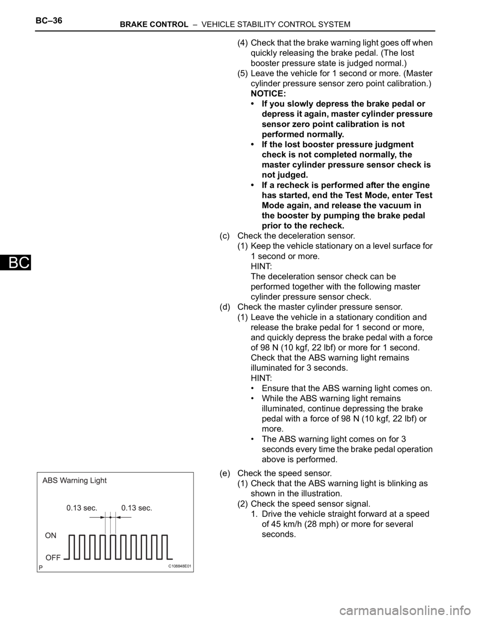
(e) Check the speed sensor.
(1) Check that the ABS warning light is blinking as
shown in the illustration.
(2) Check the speed sensor signal.
1. Drive the vehicle straight forward at a speed
of 45 km/h (28 mph) or more for several
seconds.
C108848E01
Page 1565 of 2000
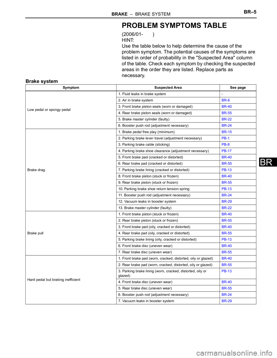
BRAKE – BRAKE SYSTEMBR–5
BR
PROBLEM SYMPTOMS TABLE
(2006/01- )
HINT:
Use the table below to help determine the cause of the
problem symptom. The potential causes of the symptoms are
listed in order of probability in the "Suspected Area" column
of the table. Check each symptom by checking the suspected
areas in the order they are listed. Replace parts as
necessary.
Brake system
Symptom Suspected Area See page
Low pedal or spongy pedal1. Fluid leaks in brake system -
2. Air in brake systemBR-6
3. Front brake piston seals (worn or damaged)BR-40
4. Rear brake piston seals (worn or damaged)BR-55
5. Brake master cylinder (faulty)BR-22
6. Booster push rod (adjustment necessary)BR-24
Brake drag1. Brake pedal free play (minimum)BR-15
2. Parking brake lever travel (adjustment necessary)PB-1
3. Parking brake cable (sticking)PB-8
4. Parking brake shoe clearance (adjustment necessary)PB-17
5. Front brake pad (cracked or distorted)BR-40
6. Rear brake pad (cracked or distorted)BR-55
7. Parking brake lining (cracked or distorted)PB-13
8. Front brake piston (stuck or frozen)BR-40
9. Rear brake piston (stuck or frozen)BR-55
10. Parking brake shoe return tension springPB-13
11. Booster push rod (adjustment necessary)BR-24
12. Vacuum leaks in booster systemBR-29
13. Brake master cylinder (faulty)BR-22
Brake pull1. Front brake piston (stuck or frozen)BR-40
2. Rear brake piston (stuck or frozen)BR-55
3. Front brake pad (oily, cracked or distorted)BR-40
4. Rear brake pad (oily, cracked or distorted)BR-55
5. Parking brake lining (oily, cracked or distorted)PB-13
6. Front brake disc (uneven wear)BR-40
7. Rear brake disc (uneven wear)BR-55
Hard pedal but braking inefficient1. Front brake pad (worn, cracked, distorted, oily or glazed)BR-40
2. Rear brake pad (worn, cracked, distorted, oily or glazed)BR-55
3. Parking brake lining (worn, cracked, distorted, oily or
glazed)PB-13
4. Front brake disc (uneven wear)BR-40
5. Rear brake disc (uneven wear)BR-55
6. Booster push rod (adjustment necessary)BR-24
7. Vacuum leaks in booster systemBR-29
Page 1569 of 2000
BR–14BRAKE – BRAKE PEDAL
BR
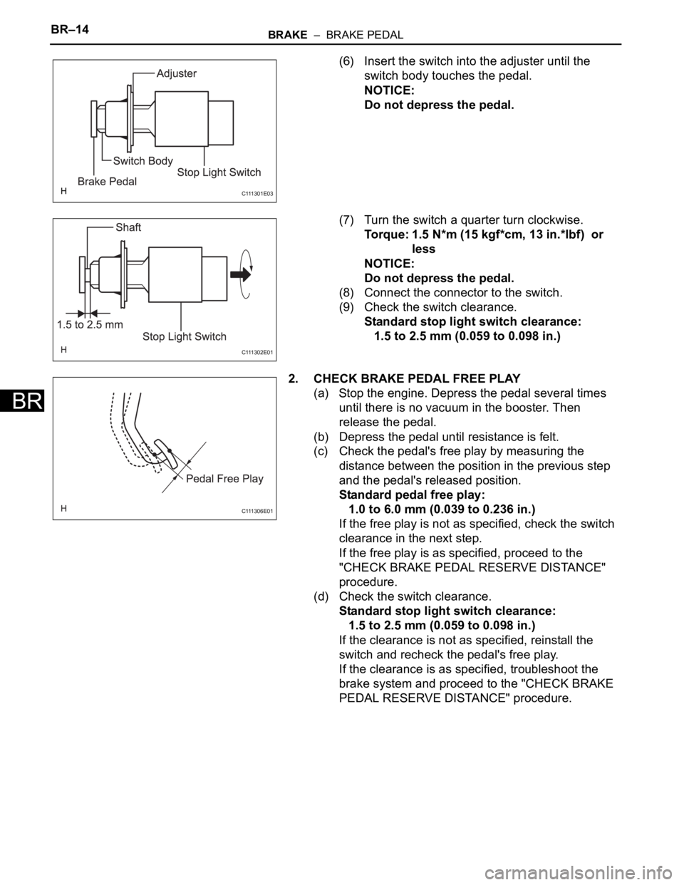
(6) Insert the switch into the adjuster until the
switch body touches the pedal.
NOTICE:
Do not depress the pedal.
(7) Turn the switch a quarter turn clockwise.
Torque: 1.5 N*m (15 kgf*cm, 13 in.*lbf) or
less
NOTICE:
Do not depress the pedal.
(8) Connect the connector to the switch.
(9) Check the switch clearance.
Standard stop light switch clearance:
1.5 to 2.5 mm (0.059 to 0.098 in.)
2. CHECK BRAKE PEDAL FREE PLAY
(a) Stop the engine. Depress the pedal several times
until there is no vacuum in the booster. Then
release the pedal.
(b) Depress the pedal until resistance is felt.
(c) Check the pedal's free play by measuring the
distance between the position in the previous step
and the pedal's released position.
Standard pedal free play:
1.0 to 6.0 mm (0.039 to 0.236 in.)
If the free play is not as specified, check the switch
clearance in the next step.
If the free play is as specified, proceed to the
"CHECK BRAKE PEDAL RESERVE DISTANCE"
procedure.
(d) Check the switch clearance.
Standard stop light switch clearance:
1.5 to 2.5 mm (0.059 to 0.098 in.)
If the clearance is not as specified, reinstall the
switch and recheck the pedal's free play.
If the clearance is as specified, troubleshoot the
brake system and proceed to the "CHECK BRAKE
PEDAL RESERVE DISTANCE" procedure.
C 111 3 0 1 E 0 3
C 111 3 0 2 E 0 1
C 111 3 0 6 E 0 1
Page 1571 of 2000
BR–16BRAKE – BRAKE PEDAL
BR
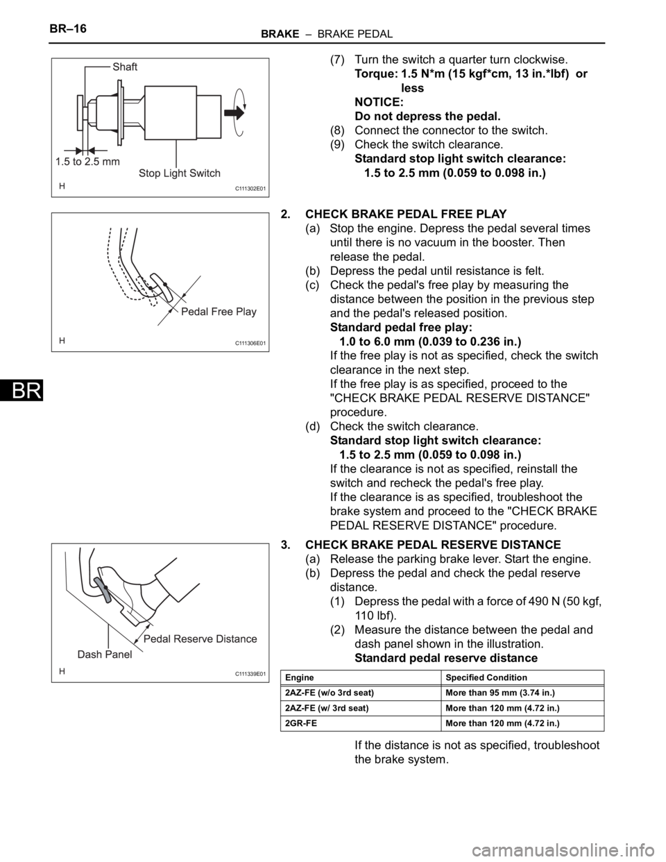
(7) Turn the switch a quarter turn clockwise.
Torque: 1.5 N*m (15 kgf*cm, 13 in.*lbf) or
less
NOTICE:
Do not depress the pedal.
(8) Connect the connector to the switch.
(9) Check the switch clearance.
Standard stop light switch clearance:
1.5 to 2.5 mm (0.059 to 0.098 in.)
2. CHECK BRAKE PEDAL FREE PLAY
(a) Stop the engine. Depress the pedal several times
until there is no vacuum in the booster. Then
release the pedal.
(b) Depress the pedal until resistance is felt.
(c) Check the pedal's free play by measuring the
distance between the position in the previous step
and the pedal's released position.
Standard pedal free play:
1.0 to 6.0 mm (0.039 to 0.236 in.)
If the free play is not as specified, check the switch
clearance in the next step.
If the free play is as specified, proceed to the
"CHECK BRAKE PEDAL RESERVE DISTANCE"
procedure.
(d) Check the switch clearance.
Standard stop light switch clearance:
1.5 to 2.5 mm (0.059 to 0.098 in.)
If the clearance is not as specified, reinstall the
switch and recheck the pedal's free play.
If the clearance is as specified, troubleshoot the
brake system and proceed to the "CHECK BRAKE
PEDAL RESERVE DISTANCE" procedure.
3. CHECK BRAKE PEDAL RESERVE DISTANCE
(a) Release the parking brake lever. Start the engine.
(b) Depress the pedal and check the pedal reserve
distance.
(1) Depress the pedal with a force of 490 N (50 kgf,
11 0 l b f ) .
(2) Measure the distance between the pedal and
dash panel shown in the illustration.
Standard pedal reserve distance
If the distance is not as specified, troubleshoot
the brake system.
C 111 3 0 2 E 0 1
C 111 3 0 6 E 0 1
C 111 3 3 9 E 0 1Engine Specified Condition
2AZ-FE (w/o 3rd seat) More than 95 mm (3.74 in.)
2AZ-FE (w/ 3rd seat) More than 120 mm (4.72 in.)
2GR-FE More than 120 mm (4.72 in.)