2006 TOYOTA RAV4 power steering
[x] Cancel search: power steeringPage 221 of 2000

INTRODUCTION – TERMSIN–49
IN
IAT Intake Air Temperature Intake or Inlet Air Temperature
ICM Ignition Control Module -
IFI Indirect Fuel Injection Indirect Injection (IDL)
IFS Inertia Fuel-Shutoff -
ISC Idle Speed Control -
KS Knock Sensor Knock Sensor
MAF Mass Airflow Air Flow Meter
MAP Manifold Absolute Pressure Manifold Pressure Intake Vacuum
MC Mixture ControlElectric Bleed Air Control Valve (EBCV)
Mixture Control Valve (MCV)
Electric Air Control Valve (EACV)
MDP Manifold Differential Pressure -
MFI Multiport Fuel Injection Electronic Fuel Injection (EFI)
MIL Malfunction Indicator Lamp Check Engine Lamp
MST Manifold Surface Temperature -
MVZ Manifold Vacuum Zone -
NVRAM Non-Volatile Random Access Memory -
O2S Oxygen Sensor Oxygen Sensor, O2 Sensor (O2S)
OBD On-Board Diagnostic On-Board Diagnostic System (OBD)
OC Oxidation Catalytic Converter Oxidation Catalyst Converter (OC), CCo
OL Open Loop Open Loop
PAIR Pulsed Secondary Air Injection Air Suction (AS)
PCM Powertrain Control Module -
PNP Park/Neutral Position -
PROM Programmable Read Only Memory -
PSP Power Steering Pressure -
PTOX Periodic Trap OxidizerDiesel Particulate Filter (DPF)
Diesel Particulate Trap (DPT)
RAM Random Access Memory Random Access Memory (RAM)
RM Relay Module -
ROM Read Only Memory Read Only Memory (ROM)
RPM Engine Speed Engine Speed
SC Supercharger Supercharger
SCB Supercharger Bypass E-ABV
SFI Sequential Multiport Fuel Injection Electronic Fuel Injection (EFI), Sequential Injection
SPL Smoke Puff Limiter -
SRI Service Reminder Indicator -
SRT System Readiness Test -
ST Scan Tool -
TB Throttle Body Throttle Body
TBI Throttle Body Fuel InjectionSingle Point Injection
Central Fuel Injection (Ci)
TC Turbocharger Turbocharger
TCC Torque Converter Clutch Torque Converter
TCM Transmission Control Module Transmission ECU, ECT ECU
TP Throttle Position Throttle Position
TR Transmission Range -
TVV Thermal Vacuum ValveBimetallic Vacuum Switching Valve (BVSV)
Thermostatic Vacuum Switching Valve (TVSV) SAE
ABBREVIATIONSSAE TERMS TOYOTA TERMS ( )-ABBREVIATIONS
Page 329 of 2000

PREPARATION – POWER STEERINGPP–81
PP
EQUIPMENT
Torque wrench -
Page 421 of 2000

STEERING COLUMN – STEERING SYSTEMSR–3
SR
PROBLEM SYMPTOMS TABLE
(2006/01- )
HINT:
Use the table below to help determine the cause of the
problem symptom. The potential causes of the symptoms are
listed in order of probability in the "Suspected Area" column
of the table. Check each symptom by checking the suspected
areas in the order they are listed. Replace parts as
necessary.
Steering system
ON-VEHICLE INSPECTION
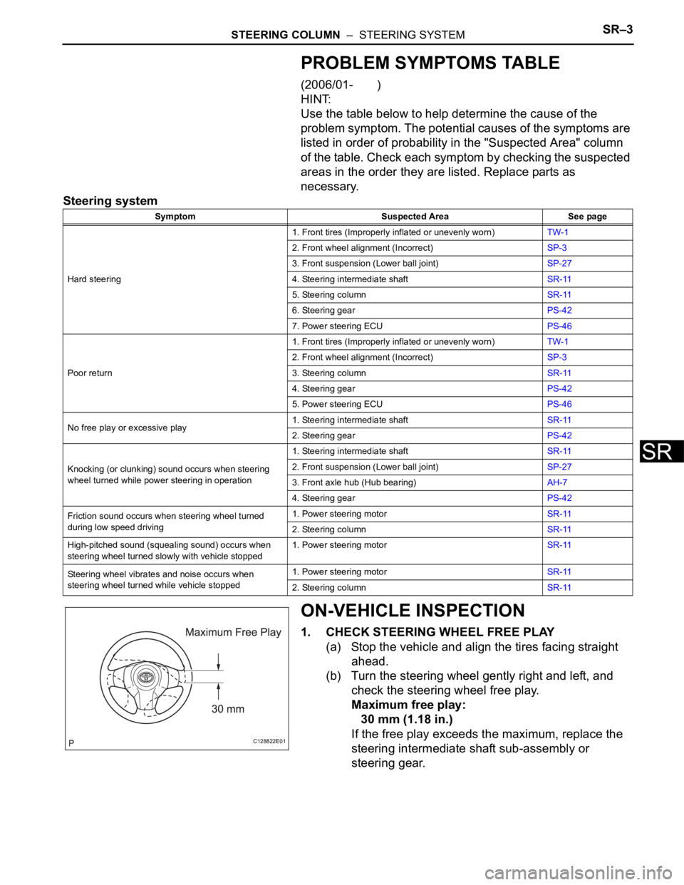
1. CHECK STEERING WHEEL FREE PLAY
(a) Stop the vehicle and align the tires facing straight
ahead.
(b) Turn the steering wheel gently right and left, and
check the steering wheel free play.
Maximum free play:
30 mm (1.18 in.)
If the free play exceeds the maximum, replace the
steering intermediate shaft sub-assembly or
steering gear.
Symptom Suspected Area See page
Hard steering1. Front tires (Improperly inflated or unevenly worn)TW-1
2. Front wheel alignment (Incorrect)SP-3
3. Front suspension (Lower ball joint)SP-27
4. Steering intermediate shaftSR-11
5. Steering columnSR-11
6. Steering gearPS-42
7. Power steering ECUPS-46
Poor return1. Front tires (Improperly inflated or unevenly worn)TW-1
2. Front wheel alignment (Incorrect)SP-3
3. Steering columnSR-11
4. Steering gearPS-42
5. Power steering ECUPS-46
No free play or excessive play1. Steering intermediate shaftSR-11
2. Steering gearPS-42
Knocking (or clunking) sound occurs when steering
wheel turned while power steering in operation1. Steering intermediate shaftSR-11
2. Front suspension (Lower ball joint)SP-27
3. Front axle hub (Hub bearing)AH-7
4. Steering gearPS-42
Friction sound occurs when steering wheel turned
during low speed driving1. Power steering motorSR-11
2. Steering columnSR-11
High-pitched sound (squealing sound) occurs when
steering wheel turned slowly with vehicle stopped1. Power steering motorSR-11
Steering wheel vibrates and noise occurs when
steering wheel turned while vehicle stopped1. Power steering motorSR-11
2. Steering columnSR-11
C128822E01
Page 423 of 2000

STEERING COLUMN – STEERING SYSTEMSR–5
SR
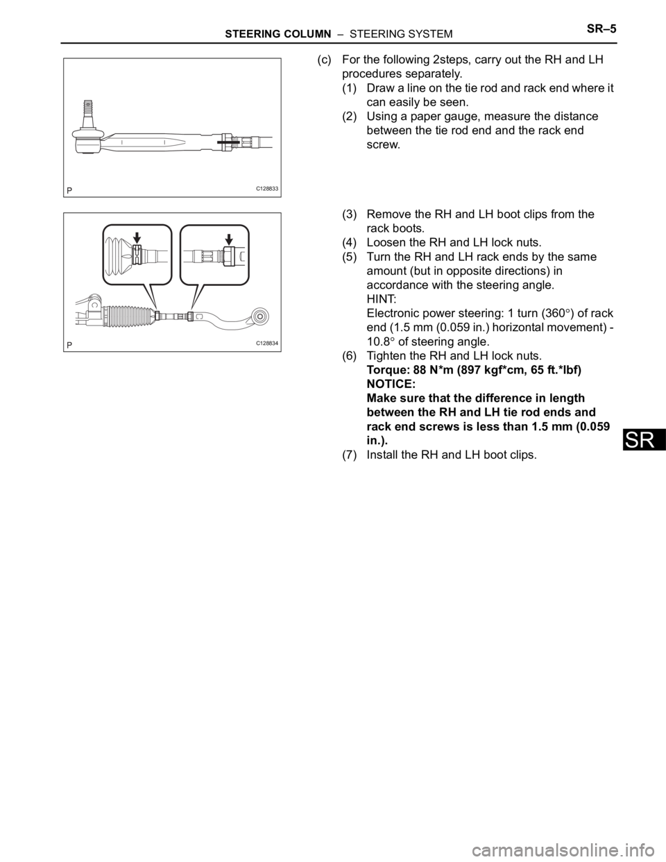
(c) For the following 2steps, carry out the RH and LH
procedures separately.
(1) Draw a line on the tie rod and rack end where it
can easily be seen.
(2) Using a paper gauge, measure the distance
between the tie rod end and the rack end
screw.
(3) Remove the RH and LH boot clips from the
rack boots.
(4) Loosen the RH and LH lock nuts.
(5) Turn the RH and LH rack ends by the same
amount (but in opposite directions) in
accordance with the steering angle.
HINT:
Electronic power steering: 1 turn (360
) of rack
end (1.5 mm (0.059 in.) horizontal movement) -
10.8
of steering angle.
(6) Tighten the RH and LH lock nuts.
Torque: 88 N*m (897 kgf*cm, 65 ft.*lbf)
NOTICE:
Make sure that the difference in length
between the RH and LH tie rod ends and
rack end screws is less than 1.5 mm (0.059
in.).
(7) Install the RH and LH boot clips.
C128833
C128834
Page 424 of 2000

PS–4POWER STEERING – ELECTRONIC POWER STEERING SYSTEM
PS
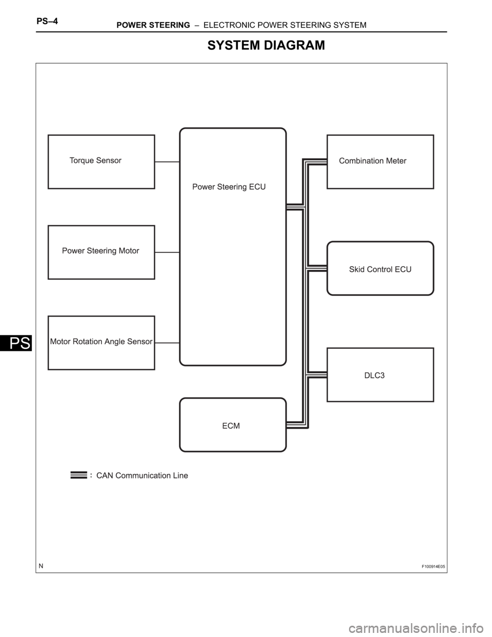
SYSTEM DIAGRAM
F100914E05
Page 425 of 2000

POWER STEERING – ELECTRONIC POWER STEERING SYSTEMPS–5
PS
SYSTEM DESCRIPTION
1. DESCRIPTION
The EPS (Electronic Power Steering) system generates
torque through the operation of the motor and the
reduction gear installed on the column shaft in order to
assist steering effort.
The power steering ECU determines directions and the
amount of assisting power in accordance with vehicle
speed signals and signals from the torque sensor built
into the steering column assembly. As a result, the power
steering adjusts the steering effort so that it is lighter
during low speed driving and heavier during high speed
driving.
(a) Power steering ECU:
The power steering ECU calculates assisting power
based on steering torque signals from the torque
sensor and vehicle speed signals from the skid
control ECU.
(b) Torque sensor:
The torque sensor detects the steering effort
generated when the steering wheel is turned and
converts it to an electrical signal.
(c) EPS motor:
The EPS motor is activated by the current from the
power steering ECU and generates torque to assist
the steering effort.
(d) Motor rotation angle sensor:
The motor rotation angle sensor consists of the
resolver sensor, which excels in reliability and
durability. The rotation angle sensor detects the
rotation angle of the motor and outputs it to the
power steering ECU. As a result, it ensures efficient
EPS control.
Page 497 of 2000

2AZ-FE ENGINE CONTROL SYSTEM – SFI SYSTEMES–43
ES
KNOCK FB VAL Feedback value of knocking -
ACCEL POS #1Absolute Accelerator Pedal Position (APP)
No.1-
ACCEL POS #2 Absolute APP No. 2 -
THROTTLE POS Throttle sensor positioning -
THROTTLE POS Throttle position -
THROTTLE POS #2 Throttle sensor positioning #2 -
THROTTLE MOT Throttle motor -
O2S B1 S2 Heated oxygen sensor outputPerforming INJ VOL or A/F CONTROL
function of ACTIVE TEST enables technician
to check output voltage of sensor
AFS B1 S1 A/F sensor outputPerforming INJ VOL or A/F CONTROL
function of ACTIVE TEST enables technician
to check output voltage of sensor
TOTAL FT #1 Total fuel trim -
SHORT FT #1 Short-term fuel trimShort-term fuel compensation used to
maintain air-fuel ratio at stoichiometric air-fuel
ratio
LONG FT #1 Long-term fuel trimOverall fuel compensation carried out in long-
term to compensate a continual deviation of
short-term fuel trim from central valve
FUEL SYS #1 Fuel system status• OL (Open Loop): Has not yet satisfied
conditions to go closed loop
• CL (Closed Loop): Using A/F sensor as
feedback for fuel control
• OL DRIVE: Open loop due to driving
conditions (fuel enrichment)
• OL FAULT: Open loop due to detected
system fault
• CL FAULT: Closed loop but A/F sensor,
which used for fuel control malfunctioning
O2FT B1 S2 Fuel trim at heated oxygen sensor -
AF FT B1 S1 Fuel trim at A/F sensor -
AFS B1 S1 A/F sensor current -
CAT TEMP B1S1 Estimated catalyst temperature (sensor 1) -
CAT TEMP B1S2 Estimated catalyst temperature (sensor 2) -
S O2S B1S2Sub heated oxygen sensor impedance
(sensor 2)-
INI COOL TEMP Engine coolant temperature at engine start -
INI INTAKE TEMP Intake air temperature at engine start -
INJ VOL Injection volume -
STARTER SIG Starter switch (STSW) signal -
PS SW Power steering signal -
PS SIGNAL Power steering signal (history)Signal status usually ON until ignition switch
turned OFF
CTP SW Closed throttle position switch -
A/C SIGNAL A/C signal -
PNP SW (NSW) Park/Neutral Position (PNP) switch signal -
ELECT LOAD SIG Electrical load signal -
STOP LIGHT SW Stop light switch -
BATTERY VOLTAGE Battery voltage -
ATM PRESSURE Atmosphere pressure -
EVAP (Purge) VSV EVAP Purge VSV -
FUEL PUMP/SPD Fuel pump/speed status -LABEL
(Intelligent Tester Display)Measurement Item Diagnostic Note
Page 571 of 2000

2GR-FE ENGINE CONTROL SYSTEM – SFI SYSTEMES–47
ES
KNOCK FB VAL Feedback value of knocking -
ACCEL POS #1Absolute Accelerator Pedal Position (APP)
No.1-
ACCEL POS #2 Absolute APP No. 2 -
THROTTLE POS Throttle sensor positioning -
THROTTLE POS Throttle position -
THROTTLE POS #2 Throttle sensor positioning #2 -
THROTTLE MOT Throttle motor -
O2S B1 S2
O2S B2 S2Heated oxygen sensor outputPerforming INJ VOL or A/F CONTROL
function of ACTIVE TEST enables technician
to check output voltage of sensor
AFS B1 S1
AFS B2 S1A/F sensor outputPerforming INJ VOL or A/F CONTROL
function of ACTIVE TEST enables technician
to check output voltage of sensor
TOTAL FT #1
TOTAL FT #2Total fuel trim -
SHORT FT #1
SHORT FT #2Short-term fuel trimShort-term fuel compensation used to
maintain air-fuel ratio at stoichiometric air-fuel
ratio
LONG FT #1
LONG FT #2Long-term fuel trimOverall fuel compensation carried out in long-
term to compensate a continual deviation of
short-term fuel trim from central valve
O2FT B1 S2
O2FT B2 S2Fuel trim at heated oxygen sensor -
AF FT B1 S1
AF FT B2 S1Fuel trim at A/F sensor-
AFS B1 S1
AFS B2 S1A/F sensor current-
CAT TEMP B1S1
CAT TEMP B2S1Estimated catalyst temperature (sensor 1)-
CAT TEMP B1S2
CAT TEMP B2S2Estimated catalyst temperature (sensor 2)-
S O2S B1S2
S O2S B2S2Sub heated oxygen sensor impedance
(sensor 2)-
INI COOL TEMP Engine coolant temperature at engine start -
INI INTAKE TEMP Intake air temperature at engine start -
INJ VOL Injection volume -
STARTER SIG Starter switch (STSW) signal -
PS SW Power steering signal -
PS SIGNAL Power steering signal (history)Signal status usually ON until ignition switch
turned OFF
CTP SW Closed throttle position switch -
A/C SIGNAL A/C signal -
PNP SW (NSW) Park/Neutral Position (PNP) switch signal -
ELECT LOAD SIG Electrical load signal -
STOP LIGHT SW Stop light switch -
BATTERY VOLTAGE Battery voltage -
ATM PRESSURE Atmosphere pressure -
FUEL PMP SP CTL Fuel pump speed control status -
ACIS VSVVSV for Acoustic Control Induction System
(ACIS)-
EVAP (Purge) VSV EVAP Purge VSV -
FUEL PUMP/SPD Fuel pump/speed status -LABEL
(Intelligent Tester Display)Measurement Item Diagnostic Note