2006 TOYOTA RAV4 brake rotor
[x] Cancel search: brake rotorPage 1363 of 2000
DRIVE SHAFT – FRONT DRIVE SHAFT ASSEMBLY (for 2WD)DS–7
DS
REMOVAL
(2005/11-2006/01)
1. REMOVE FRONT WHEEL
2. DRAIN AUTOMATIC TRANSAXLE FLUID
(a) Drain the automatic transaxle fluid for U140F (see
page AX-147).
(b) Drain the automatic transaxle fluid for U241E (see
page AX-146).
3. REMOVE FRONT AXLE HUB NUT (See page AH-6)
4. DISCONNECT FRONT SPEED SENSOR LH
(a) Disconnect the speed sensor (see page BC-191).
5. DISCONNECT FRONT SPEED SENSOR RH
HINT:
Use the same procedures described for the LH side.
6. DISCONNECT FRONT DISC BRAKE CYLINDER
ASSEMBLY LH (See page BR-40)
7. DISCONNECT FRONT DISC BRAKE CALIPER
ASSEMBLY RH
HINT:
Use the same procedures described for the LH side.
8. REMOVE FRONT STABILIZER LINK ASSEMBLY LH
(See page SP-30)
9. REMOVE FRONT STABILIZER LINK ASSEMBLY RH
HINT:
Use the same procedures described for the LH side.
10. DISCONNECT FRONT SUSPENSION LOWER NO. 1
ARM SUB-ASSEMBLY LH (See page AH-7)
11. DISCONNECT FRONT SUSPENSION LOWER NO. 1
ARM SUB-ASSEMBLY RH
HINT:
Use the same procedures described for the LH side.
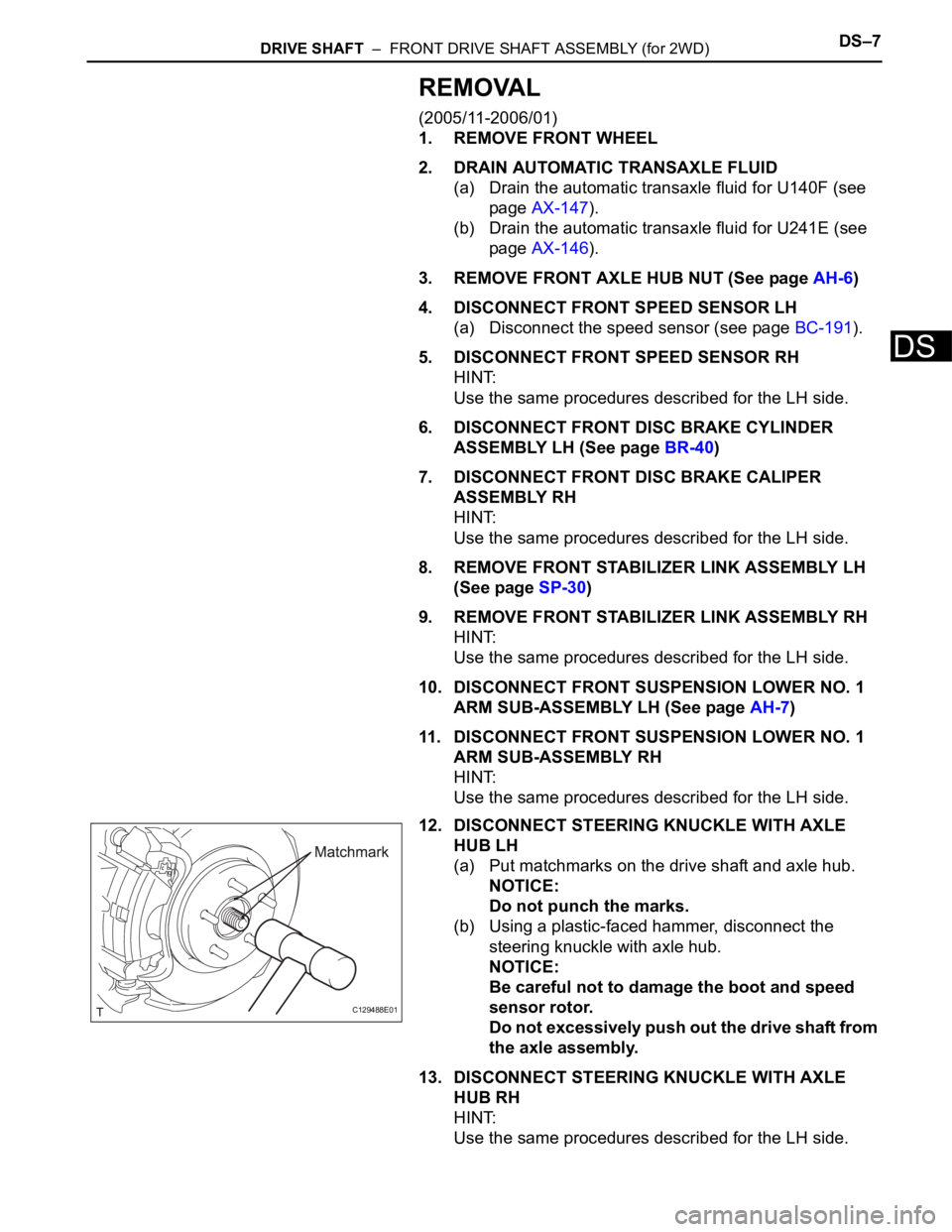
12. DISCONNECT STEERING KNUCKLE WITH AXLE
HUB LH
(a) Put matchmarks on the drive shaft and axle hub.
NOTICE:
Do not punch the marks.
(b) Using a plastic-faced hammer, disconnect the
steering knuckle with axle hub.
NOTICE:
Be careful not to damage the boot and speed
sensor rotor.
Do not excessively push out the drive shaft from
the axle assembly.
13. DISCONNECT STEERING KNUCKLE WITH AXLE
HUB RH
HINT:
Use the same procedures described for the LH side.
C129488E01
Page 1365 of 2000
DRIVE SHAFT – FRONT DRIVE SHAFT ASSEMBLY (for 2WD)DS–9
DS
REMOVAL
(2006/01- )
1. REMOVE FRONT WHEEL
2. DRAIN AUTOMATIC TRANSAXLE FLUID
(a) Drain the automatic transaxle fluid for U140F (see
page AX-147).
(b) Drain the automatic transaxle fluid for U241E (see
page AX-146).
(c) Drain the automatic transaxle fluid for U151E (see
page AX-172).
3. REMOVE FRONT AXLE HUB NUT (See page AH-8)
4. DISCONNECT FRONT SPEED SENSOR LH
(a) Disconnect the speed sensor (see page BC-191).
5. REMOVE FRONT SPEED SENSOR RH
HINT:
Use the same procedures described for the LH side.
6. DISCONNECT FRONT DISC BRAKE CYLINDER
ASSEMBLY LH (See page BR-40)
7. DISCONNECT FRONT DISC BRAKE CYLINDER
ASSEMBLY RH
HINT:
Use the same procedures described for the LH side.
8. REMOVE FRONT STABILIZER LINK ASSEMBLY LH
(See page SP-30)
9. REMOVE FRONT STABILIZER LINK ASSEMBLY RH
HINT:
Use the same procedures described for the LH side.
10. DISCONNECT FRONT SUSPENSION LOWER NO. 1
ARM SUB-ASSEMBLY LH (See page SP-21)
11. DISCONNECT FRONT SUSPENSION LOWER NO. 1
ARM SUB-ASSEMBLY RH
HINT:
Use the same procedures described for the LH side.
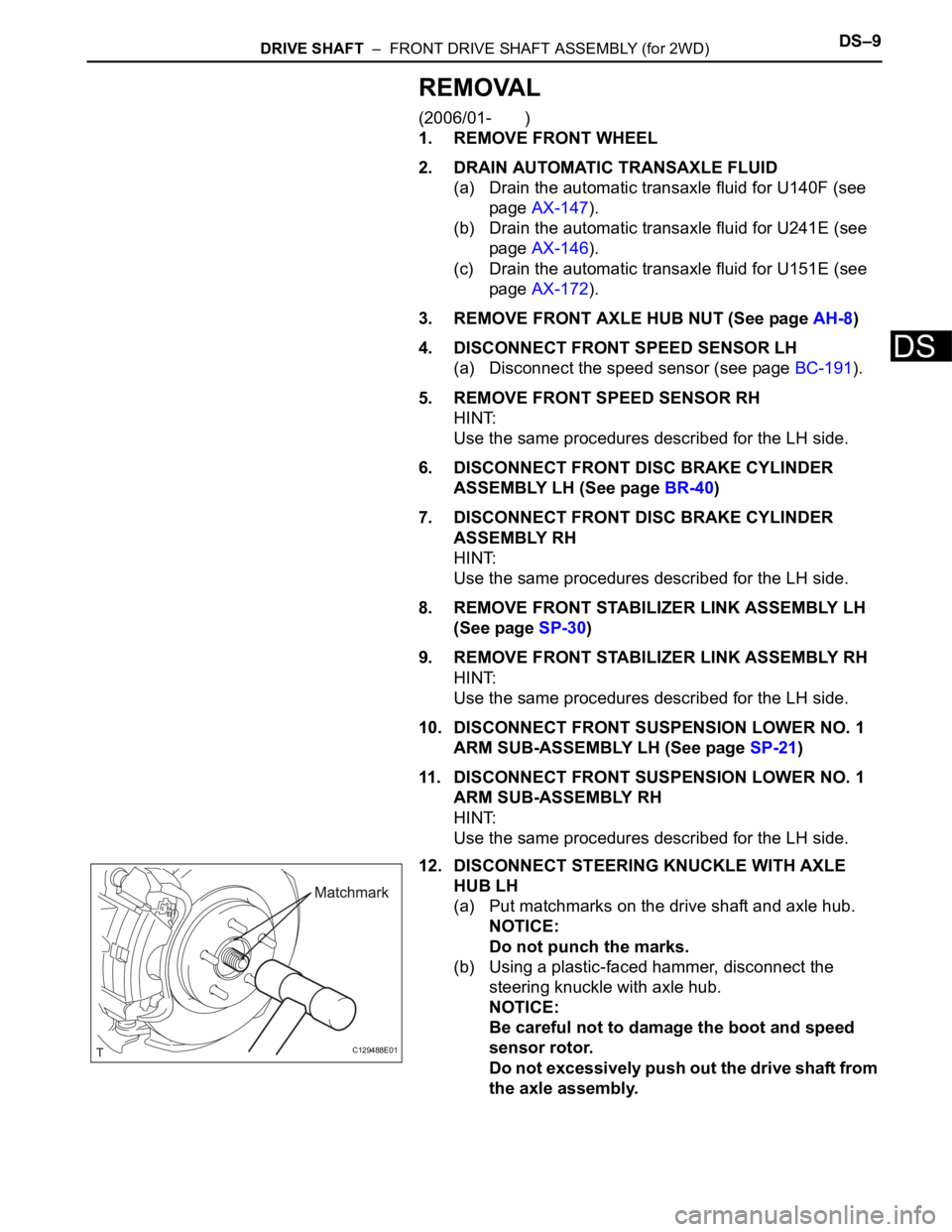
12. DISCONNECT STEERING KNUCKLE WITH AXLE
HUB LH
(a) Put matchmarks on the drive shaft and axle hub.
NOTICE:
Do not punch the marks.
(b) Using a plastic-faced hammer, disconnect the
steering knuckle with axle hub.
NOTICE:
Be careful not to damage the boot and speed
sensor rotor.
Do not excessively push out the drive shaft from
the axle assembly.
C129488E01
Page 1394 of 2000
DS–40DRIVE SHAFT – FRONT DRIVE SHAFT ASSEMBLY (for 4WD)
DS
REMOVAL
(2005/11-2006/01)
1. REMOVE FRONT WHEEL
2. DRAIN AUTOMATIC TRANSAXLE FLUID
(a) Drain the automatic transaxle fluid for U140F (see
page AX-147).
(b) Drain the automatic transaxle fluid for U241E (see
page AX-146).
3. REMOVE FRONT AXLE HUB NUT (See page AH-6)
4. DISCONNECT FRONT SPEED SENSOR LH (See page
BC-191)
5. DISCONNECT FRONT SPEED SENSOR RH
HINT:
Use the same procedures described for the LH side.
6. DISCONNECT FRONT DISC BRAKE CYLINDER
ASSEMBLY LH (See page BR-40)
7. DISCONNECT FRONT DISC BRAKE CYLINDER
ASSEMBLY RH
HINT:
Use the same procedures described for the LH side.
8. DISCONNECT FRONT STABILIZER LINK ASSEMBLY
LH (See page SP-9)
9. DISCONNECT FRONT STABILIZER LINK ASSEMBLY
RH
HINT:
Use the same procedures described for the LH side.
10. DISCONNECT FRONT SUSPENSION LOWER NO. 1
ARM SUB-ASSEMBLY LH (See page AH-7)
11. DISCONNECT FRONT SUSPENSION LOWER NO. 1
ARM SUB-ASSEMBLY RH
HINT:
Use the same procedures described for the LH side.
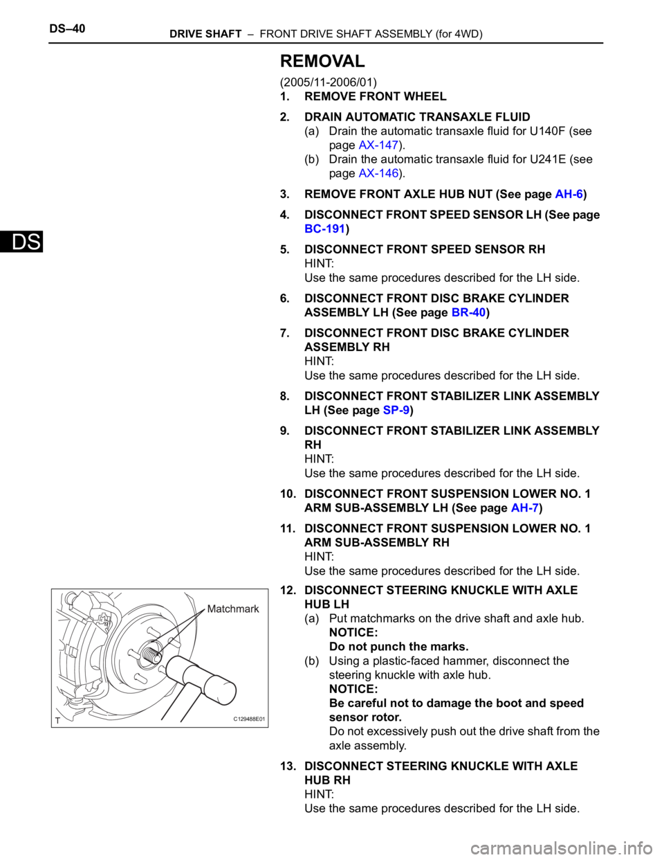
12. DISCONNECT STEERING KNUCKLE WITH AXLE
HUB LH
(a) Put matchmarks on the drive shaft and axle hub.
NOTICE:
Do not punch the marks.
(b) Using a plastic-faced hammer, disconnect the
steering knuckle with axle hub.
NOTICE:
Be careful not to damage the boot and speed
sensor rotor.
Do not excessively push out the drive shaft from the
axle assembly.
13. DISCONNECT STEERING KNUCKLE WITH AXLE
HUB RH
HINT:
Use the same procedures described for the LH side.
C129488E01
Page 1396 of 2000
DS–42DRIVE SHAFT – FRONT DRIVE SHAFT ASSEMBLY (for 4WD)
DS
REMOVAL
(2006/01- )
1. REMOVE FRONT WHEEL
2. DRAIN AUTOMATIC TRANSAXLE FLUID
(a) Drain the automatic transaxle fluid for U140F (see
page AX-147).
(b) Drain the automatic transaxle fluid for U241E (see
page AX-146).
(c) Drain the automatic transaxle fluid for U151F (see
page AX-173).
3. REMOVE FRONT AXLE HUB NUT (See page AH-8)
4. DISCONNECT FRONT SPEED SENSOR LH (See page
BC-191)
5. DISCONNECT FRONT SPEED SENSOR RH
HINT:
Use the same procedures described for the LH side.
6. DISCONNECT FRONT DISC BRAKE CYLINDER
ASSEMBLY LH (See page BR-40)
7. DISCONNECT FRONT DISC BRAKE CYLINDER
ASSEMBLY RH
HINT:
Use the same procedures described for the LH side.
8. DISCONNECT FRONT STABILIZER LINK ASSEMBLY
LH (See page SP-30)
9. DISCONNECT FRONT STABILIZER LINK ASSEMBLY
RH
10. DISCONNECT FRONT SUSPENSION LOWER NO. 1
ARM SUB-ASSEMBLY LH (See page SP-22)
11. DISCONNECT FRONT SUSPENSION LOWER NO. 1
ARM SUB-ASSEMBLY RH
HINT:
Use the same procedures described for the LH side.
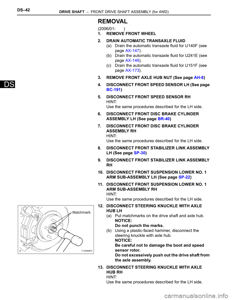
12. DISCONNECT STEERING KNUCKLE WITH AXLE
HUB LH
(a) Put matchmarks on the drive shaft and axle hub.
NOTICE:
Do not punch the marks.
(b) Using a plastic-faced hammer, disconnect the
steering knuckle with axle hub.
NOTICE:
Be careful not to damage the boot and speed
sensor rotor.
Do not excessively push out the drive shaft from
the axle assembly.
13. DISCONNECT STEERING KNUCKLE WITH AXLE
HUB RH
HINT:
Use the same procedures described for the LH side.
C129488E01
Page 1452 of 2000
AXLE – FRONT AXLE HUBAH–11
AH
INSTALLATION
(2005/11-2006/01)
HINT:
• Use the same procedures for the RH side and LH side.
• The procedures listed below are for the LH side.
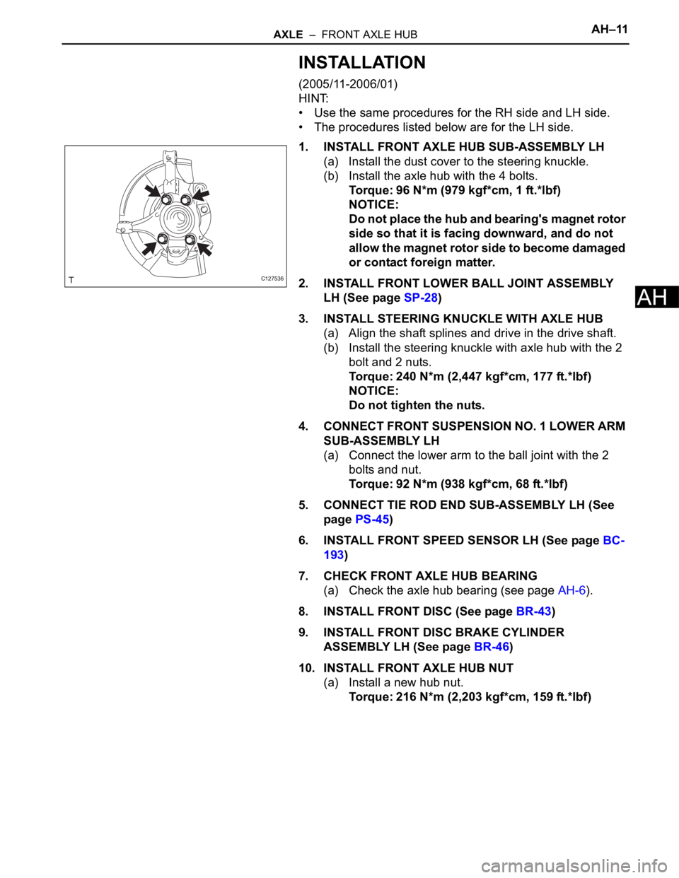
1. INSTALL FRONT AXLE HUB SUB-ASSEMBLY LH
(a) Install the dust cover to the steering knuckle.
(b) Install the axle hub with the 4 bolts.
Torque: 96 N*m (979 kgf*cm, 1 ft.*lbf)
NOTICE:
Do not place the hub and bearing's magnet rotor
side so that it is facing downward, and do not
allow the magnet rotor side to become damaged
or contact foreign matter.
2. INSTALL FRONT LOWER BALL JOINT ASSEMBLY
LH (See page SP-28)
3. INSTALL STEERING KNUCKLE WITH AXLE HUB
(a) Align the shaft splines and drive in the drive shaft.
(b) Install the steering knuckle with axle hub with the 2
bolt and 2 nuts.
Torque: 240 N*m (2,447 kgf*cm, 177 ft.*lbf)
NOTICE:
Do not tighten the nuts.
4. CONNECT FRONT SUSPENSION NO. 1 LOWER ARM
SUB-ASSEMBLY LH
(a) Connect the lower arm to the ball joint with the 2
bolts and nut.
Torque: 92 N*m (938 kgf*cm, 68 ft.*lbf)
5. CONNECT TIE ROD END SUB-ASSEMBLY LH (See
page PS-45)
6. INSTALL FRONT SPEED SENSOR LH (See page BC-
193)
7. CHECK FRONT AXLE HUB BEARING
(a) Check the axle hub bearing (see page AH-6).
8. INSTALL FRONT DISC (See page BR-43)
9. INSTALL FRONT DISC BRAKE CYLINDER
ASSEMBLY LH (See page BR-46)
10. INSTALL FRONT AXLE HUB NUT
(a) Install a new hub nut.
Torque: 216 N*m (2,203 kgf*cm, 159 ft.*lbf)
C127536
Page 1454 of 2000
AXLE – FRONT AXLE HUBAH–13
AH
INSTALLATION
(2006/01- )
HINT:
• Use the same procedures for the RH side and LH side.
• The procedures listed below are the LH side.
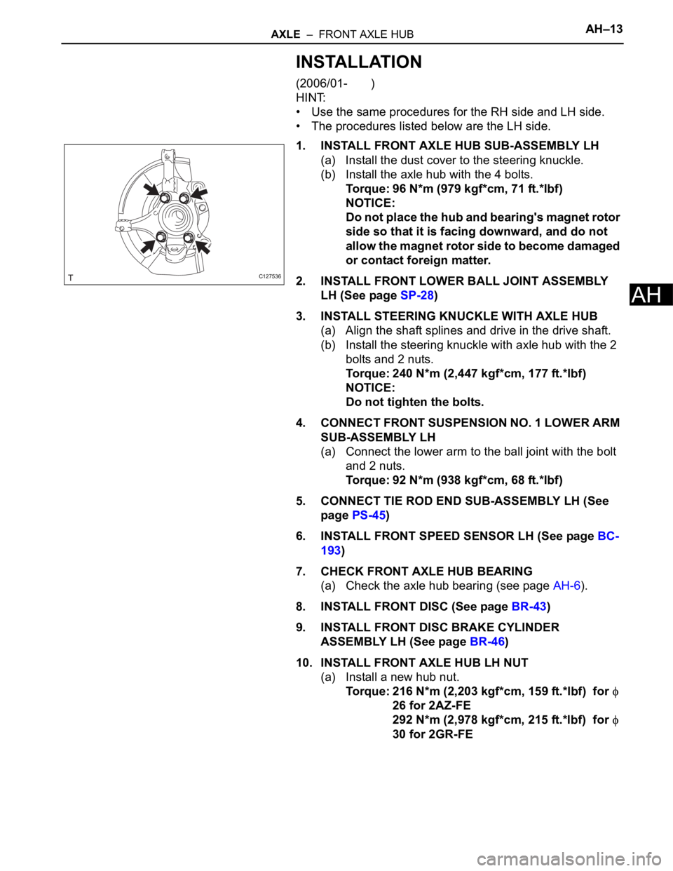
1. INSTALL FRONT AXLE HUB SUB-ASSEMBLY LH
(a) Install the dust cover to the steering knuckle.
(b) Install the axle hub with the 4 bolts.
Torque: 96 N*m (979 kgf*cm, 71 ft.*lbf)
NOTICE:
Do not place the hub and bearing's magnet rotor
side so that it is facing downward, and do not
allow the magnet rotor side to become damaged
or contact foreign matter.
2. INSTALL FRONT LOWER BALL JOINT ASSEMBLY
LH (See page SP-28)
3. INSTALL STEERING KNUCKLE WITH AXLE HUB
(a) Align the shaft splines and drive in the drive shaft.
(b) Install the steering knuckle with axle hub with the 2
bolts and 2 nuts.
Torque: 240 N*m (2,447 kgf*cm, 177 ft.*lbf)
NOTICE:
Do not tighten the bolts.
4. CONNECT FRONT SUSPENSION NO. 1 LOWER ARM
SUB-ASSEMBLY LH
(a) Connect the lower arm to the ball joint with the bolt
and 2 nuts.
Torque: 92 N*m (938 kgf*cm, 68 ft.*lbf)
5. CONNECT TIE ROD END SUB-ASSEMBLY LH (See
page PS-45)
6. INSTALL FRONT SPEED SENSOR LH (See page BC-
193)
7. CHECK FRONT AXLE HUB BEARING
(a) Check the axle hub bearing (see page AH-6).
8. INSTALL FRONT DISC (See page BR-43)
9. INSTALL FRONT DISC BRAKE CYLINDER
ASSEMBLY LH (See page BR-46)
10. INSTALL FRONT AXLE HUB LH NUT
(a) Install a new hub nut.
Torque: 216 N*m (2,203 kgf*cm, 159 ft.*lbf) for
26 for 2AZ-FE
292 N*m (2,978 kgf*cm, 215 ft.*lbf) for
30 for 2GR-FE
C127536
Page 1457 of 2000
AXLE – REAR AXLE HUB AND BEARINGAH–17
AH
REMOVAL
1. REMOVE REAR WHEEL
2. DISCONNECT CABLE FROM NEGATIVE BATTERY
TERMINAL
CAUTION:
Wait at least 90 seconds after disconnecting the
cable from the negative (-) battery terminal to
prevent airbag and seat belt pretensioner activation.
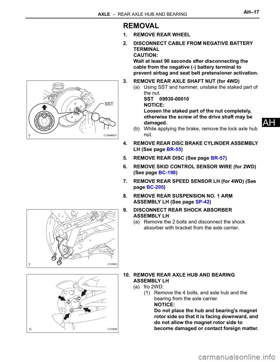
3. REMOVE REAR AXLE SHAFT NUT (for 4WD)
(a) Using SST and hammer, unstake the staked part of
the nut.
SST 09930-00010
NOTICE:
Loosen the staked part of the nut completely,
otherwise the screw of the drive shaft may be
damaged.
(b) While applying the brake, remove the lock axle hub
nut.
4. REMOVE REAR DISC BRAKE CYLINDER ASSEMBLY
LH (See page BR-55)
5. REMOVE REAR DISC (See page BR-57)
6. REMOVE SKID CONTROL SENSOR WIRE (for 2WD)
(See page BC-198)
7. REMOVE REAR SPEED SENSOR LH (for 4WD) (See
page BC-205)
8. REMOVE REAR SUSPENSION NO. 1 ARM
ASSEMBLY LH (See page SP-42)
9. DISCONNECT REAR SHOCK ABSORBER
ASSEMBLY LH
(a) Remove the 2 bolts and disconnect the shock
absorber with bracket from the axle carrier.
10. REMOVE REAR AXLE HUB AND BEARING
ASSEMBLY LH
(a) fro 2WD:
(1) Remove the 4 bolts, and axle hub and the
bearing from the axle carrier.
NOTICE:
Do not place the hub and bearing's magnet
rotor side so that it is facing downward, and
do not allow the magnet rotor side to
become damaged or contact foreign matter.
C129486E01
C129929
C130589
Page 1458 of 2000
AH–18AXLE – REAR AXLE HUB AND BEARING
AH
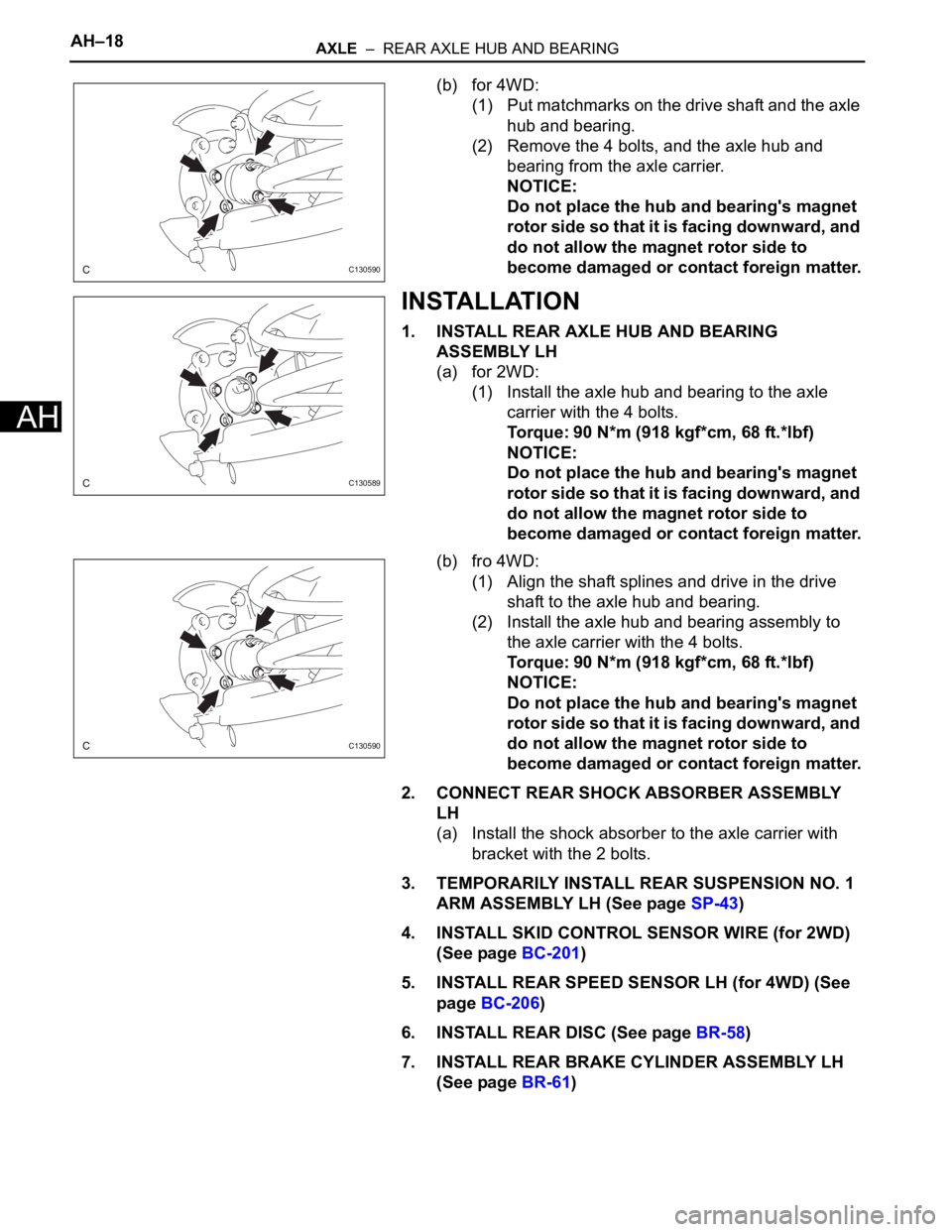
(b) for 4WD:
(1) Put matchmarks on the drive shaft and the axle
hub and bearing.
(2) Remove the 4 bolts, and the axle hub and
bearing from the axle carrier.
NOTICE:
Do not place the hub and bearing's magnet
rotor side so that it is facing downward, and
do not allow the magnet rotor side to
become damaged or contact foreign matter.
INSTALLATION
1. INSTALL REAR AXLE HUB AND BEARING
ASSEMBLY LH
(a) for 2WD:
(1) Install the axle hub and bearing to the axle
carrier with the 4 bolts.
Torque: 90 N*m (918 kgf*cm, 68 ft.*lbf)
NOTICE:
Do not place the hub and bearing's magnet
rotor side so that it is facing downward, and
do not allow the magnet rotor side to
become damaged or contact foreign matter.
(b) fro 4WD:
(1) Align the shaft splines and drive in the drive
shaft to the axle hub and bearing.
(2) Install the axle hub and bearing assembly to
the axle carrier with the 4 bolts.
Torque: 90 N*m (918 kgf*cm, 68 ft.*lbf)
NOTICE:
Do not place the hub and bearing's magnet
rotor side so that it is facing downward, and
do not allow the magnet rotor side to
become damaged or contact foreign matter.
2. CONNECT REAR SHOCK ABSORBER ASSEMBLY
LH
(a) Install the shock absorber to the axle carrier with
bracket with the 2 bolts.
3. TEMPORARILY INSTALL REAR SUSPENSION NO. 1
ARM ASSEMBLY LH (See page SP-43)
4. INSTALL SKID CONTROL SENSOR WIRE (for 2WD)
(See page BC-201)
5. INSTALL REAR SPEED SENSOR LH (for 4WD) (See
page BC-206)
6. INSTALL REAR DISC (See page BR-58)
7. INSTALL REAR BRAKE CYLINDER ASSEMBLY LH
(See page BR-61)
C130590
C130589
C130590