Page 381 of 2000

SS–14SERVICE SPECIFICATIONS – 2AZ-FE ENGINE MECHANICAL
SS
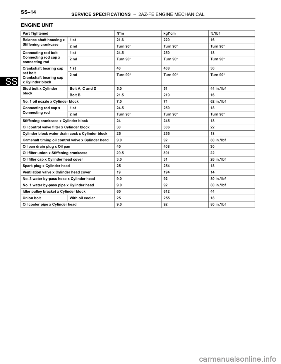
ENGINE UNIT
Part Tightened N*m kgf*cm ft.*lbf
Balance shaft housing x
Stiffening crankcase1 st 21.6 220 16
2 nd Turn 90
Tu r n 9 0Tu r n 9 0
Connecting rod bolt
Connecting rod cap x
connecting rod1 st 24.5 250 18
2 nd Turn 90
Tu r n 9 0Tu r n 9 0
Crankshaft bearing cap
set bolt
Crankshaft bearing cap
x Cylinder block1 st 40 408 30
2 nd Turn 90
Tu r n 9 0Tu r n 9 0
Stud bolt x Cylinder
blockBolt A, C and D 5.0 51 44 in.*lbf
Bolt B 21.5 219 16
No. 1 oil nozzle x Cylinder block 7.0 71 62 in.*lbf
Connecting rod cap x
Connecting rod1 st 24.5 250 18
2 nd Turn 90
Tu r n 9 0Tu r n 9 0
Stiffening crankcase x Cylinder block 24 245 18
Oil control valve filter x Cylinder block 30 306 22
Cylinder block water drain cock x Cylinder block 25 255 18
Camshaft timing oil control valve x Cylinder head 9.0 92 80 in.*lbf
Oil pan drain plug x Oil pan 40 408 30
Oil filter union x Stiffening crankcase 29.5 301 22
Oil filler cap x Cylinder head cover 3.0 31 26 in.*lbf
Spark plug x Cylinder head 25 254 18
Ventilation valve x Cylinder head cover 19 194 14
No. 3 water by-pass hose x Cylinder head 9.0 92 80 in.*lbf
No. 1 water by-pass pipe x Cylinder head 9.0 92 80 in.*lbf
Idler pulley bracket x Cylinder block 60 612 44
Union bolt With oil cooler 25 255 18
Oil cooler pipe x Cylinder head 9.0 92 80 in.*lbf
Page 384 of 2000

SS–22SERVICE SPECIFICATIONS – 2GR-FE ENGINE MECHANICAL
SS
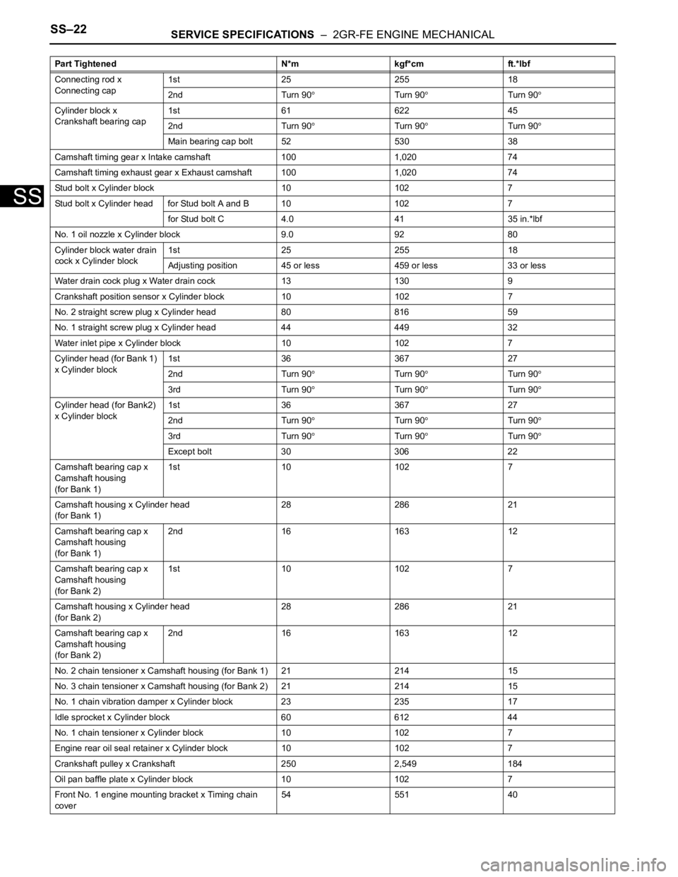
Connecting rod x
Connecting cap1st 25 255 18
2nd Turn 90
Turn 90Turn 90
Cylinder block x
Crankshaft bearing cap1st 61 622 45
2nd Turn 90
Turn 90Turn 90
Main bearing cap bolt 52 530 38
Camshaft timing gear x Intake camshaft 100 1,020 74
Camshaft timing exhaust gear x Exhaust camshaft 100 1,020 74
Stud bolt x Cylinder block 10 102 7
Stud bolt x Cylinder head for Stud bolt A and B 10 102 7
for Stud bolt C 4.0 41 35 in.*lbf
No. 1 oil nozzle x Cylinder block 9.0 92 80
Cylinder block water drain
cock x Cylinder block1st 25 255 18
Adjusting position 45 or less 459 or less 33 or less
Water drain cock plug x Water drain cock 13 130 9
Crankshaft position sensor x Cylinder block 10 102 7
No. 2 straight screw plug x Cylinder head 80 816 59
No. 1 straight screw plug x Cylinder head 44 449 32
Water inlet pipe x Cylinder block 10 102 7
Cylinder head (for Bank 1)
x Cylinder block1st 36 367 27
2nd Turn 90
Turn 90Turn 90
3rd Turn 90Turn 90Turn 90
Cylinder head (for Bank2)
x Cylinder block1st 36 367 27
2nd Turn 90
Turn 90Turn 90
3rd Turn 90Turn 90Turn 90
Except bolt 30 306 22
Camshaft bearing cap x
Camshaft housing
(for Bank 1)1st 10 102 7
Camshaft housing x Cylinder head
(for Bank 1)28 286 21
Camshaft bearing cap x
Camshaft housing
(for Bank 1)2nd 16 163 12
Camshaft bearing cap x
Camshaft housing
(for Bank 2)1st 10 102 7
Camshaft housing x Cylinder head
(for Bank 2)28 286 21
Camshaft bearing cap x
Camshaft housing
(for Bank 2)2nd 16 163 12
No. 2 chain tensioner x Camshaft housing (for Bank 1) 21 214 15
No. 3 chain tensioner x Camshaft housing (for Bank 2) 21 214 15
No. 1 chain vibration damper x Cylinder block 23 235 17
Idle sprocket x Cylinder block 60 612 44
No. 1 chain tensioner x Cylinder block 10 102 7
Engine rear oil seal retainer x Cylinder block 10 102 7
Crankshaft pulley x Crankshaft 250 2,549 184
Oil pan baffle plate x Cylinder block 10 102 7
Front No. 1 engine mounting bracket x Timing chain
cover54 551 40 Part Tightened N*m kgf*cm ft.*lbf
Page 653 of 2000

EM–1262AZ-FE ENGINE MECHANICAL – ENGINE UNIT
EM
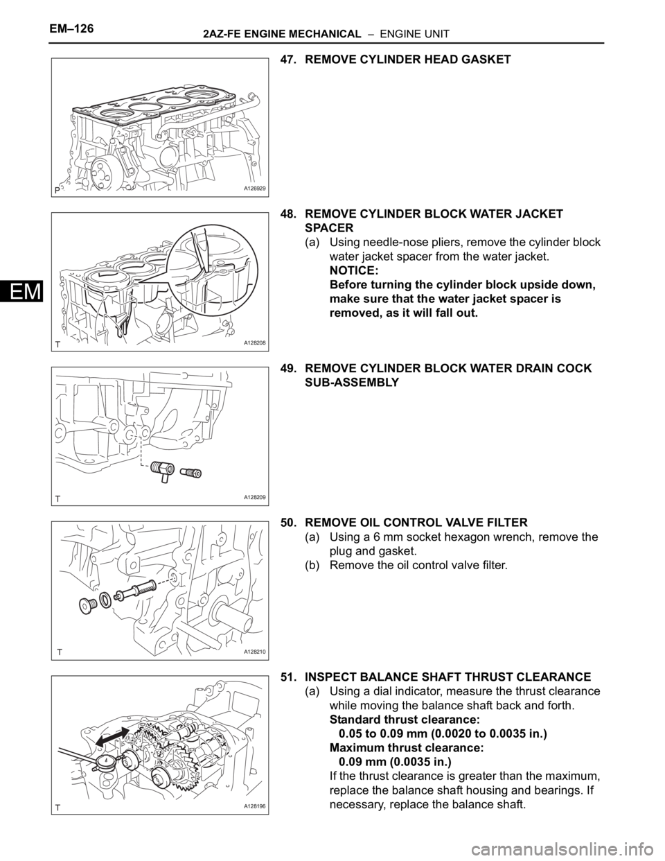
47. REMOVE CYLINDER HEAD GASKET
48. REMOVE CYLINDER BLOCK WATER JACKET
SPACER
(a) Using needle-nose pliers, remove the cylinder block
water jacket spacer from the water jacket.
NOTICE:
Before turning the cylinder block upside down,
make sure that the water jacket spacer is
removed, as it will fall out.
49. REMOVE CYLINDER BLOCK WATER DRAIN COCK
SUB-ASSEMBLY
50. REMOVE OIL CONTROL VALVE FILTER
(a) Using a 6 mm socket hexagon wrench, remove the
plug and gasket.
(b) Remove the oil control valve filter.
51. INSPECT BALANCE SHAFT THRUST CLEARANCE
(a) Using a dial indicator, measure the thrust clearance
while moving the balance shaft back and forth.
Standard thrust clearance:
0.05 to 0.09 mm (0.0020 to 0.0035 in.)
Maximum thrust clearance:
0.09 mm (0.0035 in.)
If the thrust clearance is greater than the maximum,
replace the balance shaft housing and bearings. If
necessary, replace the balance shaft.
A126929
A128208
A128209
A128210
A128196
Page 710 of 2000
2GR-FE ENGINE MECHANICAL – ENGINE UNITEM–73
EM
(v) Remove the upper bearings and upper thrust
washers from the cylinder block.
HINT:
Arrange the bearings and thrust washers in the
correct order.
57. REMOVE CYLINDER BLOCK WATER DRAIN COCK
SUB-ASSEMBLY
(a) Remove the 2 water drain cocks from the cylinder
block.
(b) Remove the water drain cock plugs from the water
drain cocks.
58. REMOVE NO. 1 OIL NOZZLE SUB-ASSEMBLY
(a) Using a 5 mm hexagon wrench, remove the 3 oil
nozzles.
(b) Check the oil nozzles for damage or clogging.
If necessary, replace the oil nozzle.
59. REMOVE PISTON RING SET
HINT:
Arrange the piston rings in the correct order.
(a) Using a piston ring expander, remove the 2
compression rings.
(b) Using a piston ring expander, remove the 2 side
rails.
(c) Remove the oil ring expander by hand.
A132018
A132017E01
A131986
A131938E01
Page 742 of 2000
2GR-FE ENGINE MECHANICAL – ENGINE UNITEM–105
EM
REASSEMBLY
1. INSTALL NO. 1 OIL NOZZLE SUB-ASSEMBLY
(a) Using a 5 mm hexagon wrench, install the 3 oil
nozzles with the bolts.
Torque: 9.0 N*m (92 kgf*cm, 80 in.*lbf)
2. INSTALL CYLINDER BLOCK WATER DRAIN COCK
SUB-ASSEMBLY
(a) Apply adhesive around the drain cocks.
Adhesive:
Toyota Genuine Adhesive 1324, Three Bond
1324 or Equivalent
(b) Install the cylinder block water drain cocks.
(1) Temporarily install the drain cocks.
Torque: 25 N*m (255 kgf*cm, 18 ft.*lbf)
A132040E01
A129732
A076531E01
Page 743 of 2000
EM–1062GR-FE ENGINE MECHANICAL – ENGINE UNIT
EM
(2) Within one full rotation, tighten the drain cock to
the angle shown in the illustration.
Torque: 45 N*m (459 kgf*cm, 33 ft.*lbf)
NOTICE:
Do not loosen the drain cock to adjust it. If
an adjustment is necessary, remove the
drain cock and reinstall it.
(c) Install the water drain cock plug to the water drain
cocks.
Torque: 13 N*m (130 kgf*cm, 9 ft.*lbf)
3. INSTALL PISTON WITH PIN SUB-ASSEMBLY
(a) Using a screwdriver, install a new snap ring at one
end of the piston pin hole.
HINT:
Be sure that the end gap of the snap ring is not
aligned with the pin hole cutout portion of the piston.
(b) Gradually heat the piston to approximately 80
C
(176
F).
(c) Coat the piston pin with engine oil.
A131970E01
A131876E01
A131877E01
Page 841 of 2000
2AZ-FE COOLING – WATER PUMPCO–11
CO
REMOVAL
1. DISCONNECT CABLE FROM NEGATIVE BATTERY
TERMINAL
CAUTION:
Wait at least 90 seconds after disconnecting the
cable from the negative (-) battery terminal to
prevent airbag and seat belt pretensioner activation.
2. REMOVE NO. 1 ENGINE UNDER COVER
3. REMOVE FRONT FENDER APRON RH
4. REMOVE RADIATOR SUPPORT OPENING COVER
5. DRAIN ENGINE COOLANT (See page CO-6)
6. REMOVE FRONT SUSPENSION MEMBER
REINFORCEMENT RH (See page EM-6)
7. REMOVE FAN AND GENERATOR V BELT (See page
EM-6)
8. REMOVE GENERATOR ASSEMBLY (See page CH-9)
9. REMOVE WATER PUMP PULLEY
(a) Using SST, remove the 4 bolts and water pump
pulley.
SST 09960-10010 (09962-01000, 09963-00700)
10. REMOVE WATER PUMP ASSEMBLY
(a) Remove the clamp of the crankshaft position sensor
from the water pump.
(b) Disconnect the wire of the crankshaft position
sensor from the clamp bracket.
(c) Remove the 4 bolts, 2 nuts and clamp bracket.
A098715E03
A094516E01
B012052E03
Page 842 of 2000
CO–122AZ-FE COOLING – WATER PUMP
CO
(d) Using a screwdriver, pry between the water pump
and cylinder block, and then remove the water
pump.
NOTICE:
Be careful not to damage the contact surfaces of
the water pump and cylinder block.
INSPECTION
1. INSPECT WATER PUMP ASSEMBLY
(a) Visually check the drain hole for coolant leakage.
If leakage is found, replace the water pump
assembly.
(b) Turn the pulley, and then check that the water pump
bearing moves smoothly without making a "click"
noise.
If it does not move smoothly, replace the water
pump assembly.
B012053E04
A112198