2006 TOYOTA RAV4 oil dipstick
[x] Cancel search: oil dipstickPage 182 of 2000
MAINTENANCE – UNDER HOODMA–7
MA
GENERAL MAINTENANCE
(2006/01- )
1. GENERAL NOTES
• Maintenance requirements vary depending on the
country.
• Check the maintenance schedule in the owner's
manual supplement.
• Following the maintenance schedule is mandatory.
• Determine the appropriate time to service the vehicle
using either miles driven or time elapsed, whichever
reaches the specification first.
• Maintain similar intervals between periodic
maintenance, unless otherwise noted.
• Failing to check each vehicle part could lead to poor
engine performance and increase exhaust emissions.
2. WINDSHIELD WASHER FLUID
(a) Check that there is sufficient fluid in the tank.
3. ENGINE COOLANT LEVEL
(a) Check that the coolant level is between the "FULL"
and "LOW" lines on the see-through reservoir.
4. RADIATOR AND HOSES
(a) Check that the front of the radiator is clean and not
blocked by leaves, dirt or bugs.
(b) Check the hoses for cracks, kinks, rot or loose
connections.
5. BATTERY ELECTROLYTE LEVEL
(a) Check that the electrolyte level of all the battery
cells is between the upper and lower level lines on
the case.
HINT:
If the electrolyte level is difficult to see, lightly shake
the vehicle.
6. BRAKE FLUID LEVEL
(a) Check that the brake fluid levels are near the upper
level lines on the see-through reservoirs.
7. ENGINE DRIVE BELT
(a) Check the drive belt for fraying, cracks, wear or
oiliness.
8. ENGINE OIL LEVEL
(a) Check the level on the dipstick with the engine
stopped.
9. AUTOMATIC TRANSAXLE FLUID LEVEL
10. EXHAUST SYSTEM
(a) Check for unusual exhaust sounds or abnormal
exhaust fumes. Inspect the cause and repair it.
Type See procedures
U151E See page AX-126
U151F See page AX-126
Page 204 of 2000
2GR-FE ENGINE MECHANICAL – ENGINE ASSEMBLYEM–29
EM
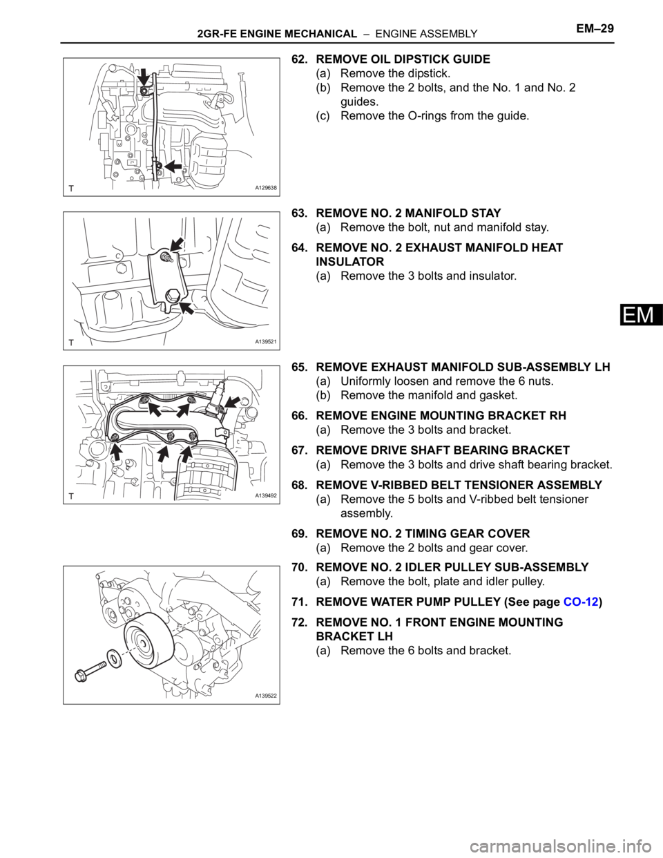
62. REMOVE OIL DIPSTICK GUIDE
(a) Remove the dipstick.
(b) Remove the 2 bolts, and the No. 1 and No. 2
guides.
(c) Remove the O-rings from the guide.
63. REMOVE NO. 2 MANIFOLD STAY
(a) Remove the bolt, nut and manifold stay.
64. REMOVE NO. 2 EXHAUST MANIFOLD HEAT
INSULATOR
(a) Remove the 3 bolts and insulator.
65. REMOVE EXHAUST MANIFOLD SUB-ASSEMBLY LH
(a) Uniformly loosen and remove the 6 nuts.
(b) Remove the manifold and gasket.
66. REMOVE ENGINE MOUNTING BRACKET RH
(a) Remove the 3 bolts and bracket.
67. REMOVE DRIVE SHAFT BEARING BRACKET
(a) Remove the 3 bolts and drive shaft bearing bracket.
68. REMOVE V-RIBBED BELT TENSIONER ASSEMBLY
(a) Remove the 5 bolts and V-ribbed belt tensioner
assembly.
69. REMOVE NO. 2 TIMING GEAR COVER
(a) Remove the 2 bolts and gear cover.
70. REMOVE NO. 2 IDLER PULLEY SUB-ASSEMBLY
(a) Remove the bolt, plate and idler pulley.
71. REMOVE WATER PUMP PULLEY (See page CO-12)
72. REMOVE NO. 1 FRONT ENGINE MOUNTING
BRACKET LH
(a) Remove the 6 bolts and bracket.
A129638
A139521
A139492
A139522
Page 227 of 2000
2AZ-FE EMISSION CONTROL – EMISSION CONTROL SYSTEMEC–7
EC
ON-VEHICLE INSPECTION
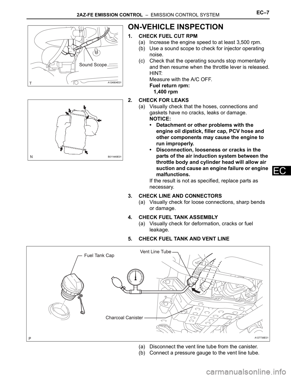
1. CHECK FUEL CUT RPM
(a) Increase the engine speed to at least 3,500 rpm.
(b) Use a sound scope to check for injector operating
noise.
(c) Check that the operating sounds stop momentarily
and then resume when the throttle lever is released.
HINT:
Measure with the A/C OFF.
Fuel return rpm:
1,400 rpm
2. CHECK FOR LEAKS
(a) Visually check that the hoses, connections and
gaskets have no cracks, leaks or damage.
NOTICE:
• Detachment or other problems with the
engine oil dipstick, filler cap, PCV hose and
other components may cause the engine to
run improperly.
• Disconnection, looseness or cracks in the
parts of the air induction system between the
throttle body and cylinder head will allow air
suction and cause an engine failure or engine
malfunctions.
If the result is not as specified, replace parts as
necessary.
3. CHECK LINE AND CONNECTORS
(a) Visually check for loose connections, sharp bends
or damage.
4. CHECK FUEL TANK ASSEMBLY
(a) Visually check for deformation, cracks or fuel
leakage.
5. CHECK FUEL TANK AND VENT LINE
(a) Disconnect the vent line tube from the canister.
(b) Connect a pressure gauge to the vent line tube.
A124804E01
B011449E01
A127736E01
Page 247 of 2000
LU–122GR-FE LUBRICATION – OIL PUMP
LU
REMOVAL
1. DISCHARGE FUEL SYSTEM PRESSURE (See page
FU-9)
2. DISCONNECT CABLE FROM NEGATIVE BATTERY
TERMINAL
CAUTION:
Wait at least 90 seconds after disconnecting the
cable from the negative (-) battery terminal to
prevent airbag and seat belt pretensioner activation.
3. REMOVE ENGINE ASSEMBLY
(a) Remove the engine from the vehicle (see page EM-
21).
4. INSTALL ENGINE TO STAND
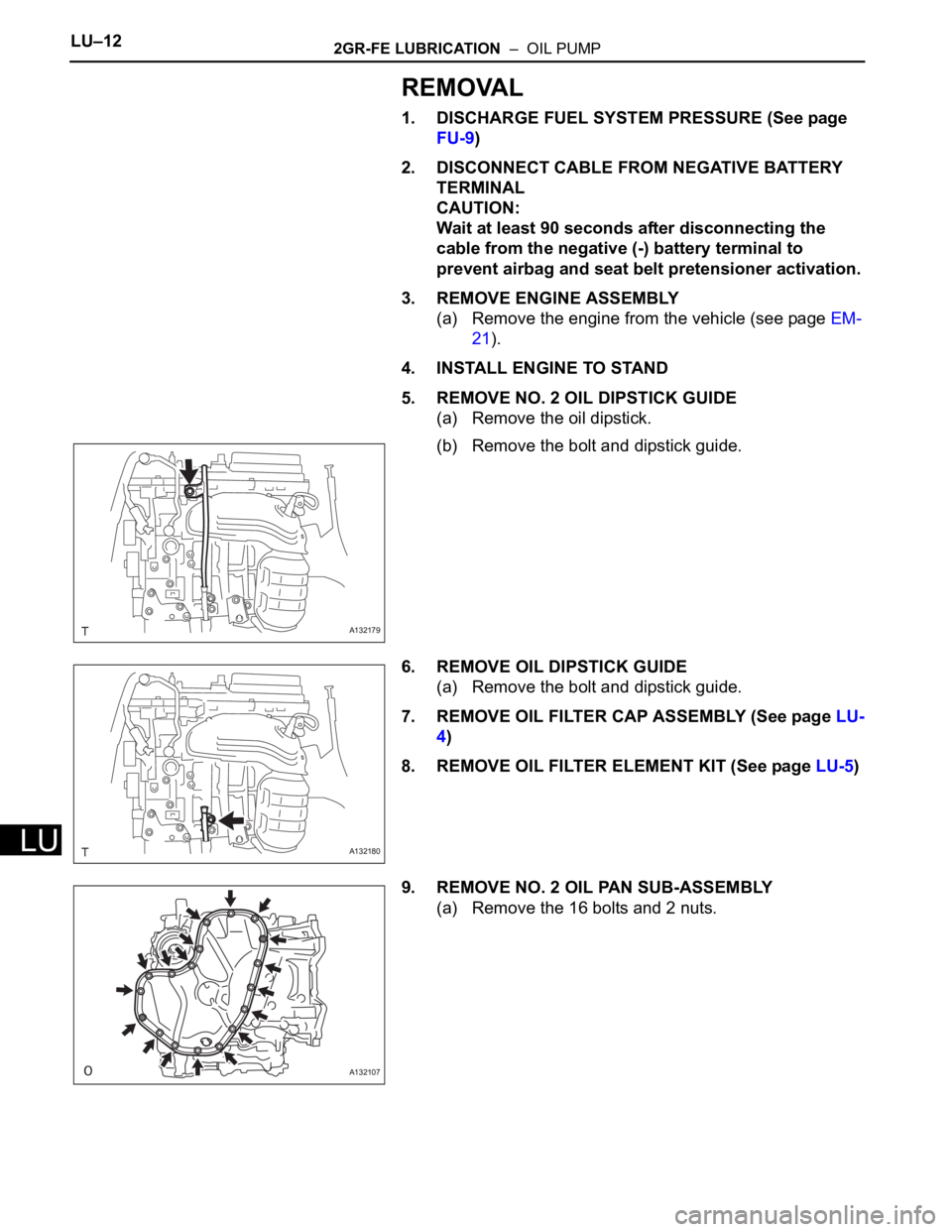
5. REMOVE NO. 2 OIL DIPSTICK GUIDE
(a) Remove the oil dipstick.
(b) Remove the bolt and dipstick guide.
6. REMOVE OIL DIPSTICK GUIDE
(a) Remove the bolt and dipstick guide.
7. REMOVE OIL FILTER CAP ASSEMBLY (See page LU-
4)
8. REMOVE OIL FILTER ELEMENT KIT (See page LU-5)
9. REMOVE NO. 2 OIL PAN SUB-ASSEMBLY
(a) Remove the 16 bolts and 2 nuts.
A132179
A132180
A132107
Page 380 of 2000
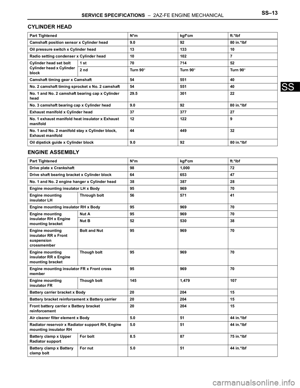
SERVICE SPECIFICATIONS – 2AZ-FE ENGINE MECHANICALSS–13
SS
CYLINDER HEAD
ENGINE ASSEMBLY
Part Tightened N*m kgf*cm ft.*lbf
Camshaft position sensor x Cylinder head 9.0 92 80 in.*lbf
Oil pressure switch x Cylinder head 13 133 10
Radio setting condenser x Cylinder head 10 102 7
Cylinder head set bolt
Cylinder head x Cylinder
block1 st 70 714 52
2 nd Turn 90
Tu r n 9 0Tu r n 9 0
Camshaft timing gear x Camshaft 54 551 40
No. 2 camshaft timing sprocket x No. 2 camshaft 54 551 40
No. 1 and No. 2 camshaft bearing cap x Cylinder
head29.5 301 22
No. 3 camshaft bearing cap x Cylinder head 9.0 92 80 in.*lbf
Exhaust manifold x Cylinder head 37 377 27
No. 1 exhaust manifold heat insulator x Exhaust
manifold12 122 9
No. 1 and No. 2 manifold stay x Cylinder block,
Exhaust manifold44 449 32
Oil dipstick guide x Cylinder block 9.0 92 80 in.*lbf
Part Tightened N*m kgf*cm ft.*lbf
Drive plate x Crankshaft 98 1,000 72
Drive shaft bearing bracket x Cylinder block 64 653 47
No. 1 and No. 2 engine hanger x Cylinder head 38 387 28
Engine mounting insulator LH x Body 95 969 70
Engine mounting
insulator LHThrough bolt 56 571 41
Engine mounting insulator RH x Body 95 969 70
Engine mounting
insulator RH x Engine
mounting bracketNut A 95 969 70
Nut B 52 530 38
Engine mounting
insulator RR x Front
suspension
crossmemberBolt and Nut 95 969 70
Engine mounting
insulator RR x Engine
mounting bracketThough bolt 95 969 70
Engine mounting insulator FR x Front cross
member95 969 70
Engine mounting
insulator FRThough bolt 145 1,479 107
Battery carrier bracket x Body 20 204 15
Battery bracket reinforcement x Battery carrier 20 204 15
Front battery carrier x Battery bracket
reinforcement20 204 15
Air cleaner filter element x Body 5.0 51 44 in.*lbf
Radiator reservoir x Radiator support RH, Engine
mounting insulator RH5.0 51 44 in.*lbf
Battery clamp x Upper
Radiator supportFor bolt 8.5 87 75 in.*lbf
Battery clamp x Battery
clamp boltFor nut 5.0 51 44 in.*lbf
Page 383 of 2000
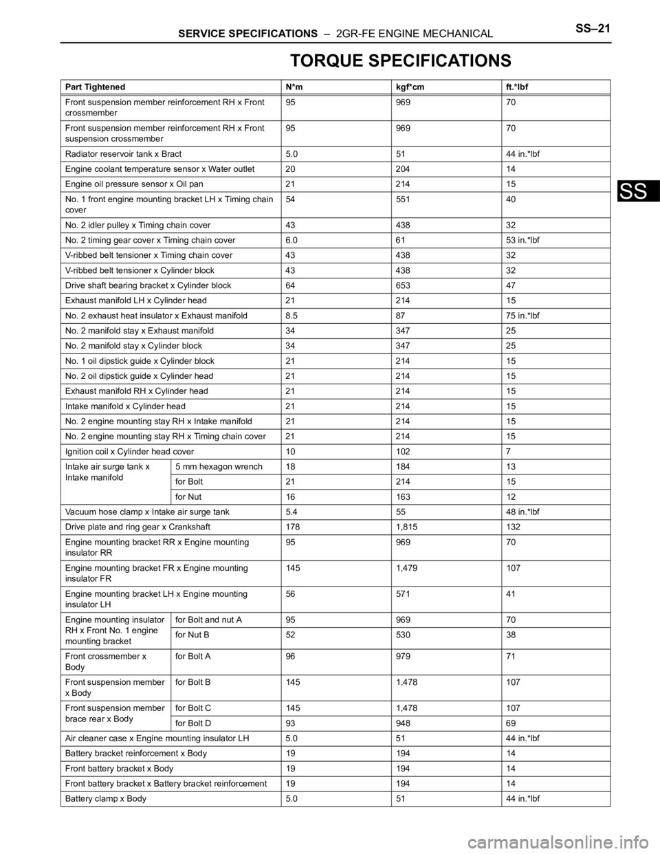
SERVICE SPECIFICATIONS – 2GR-FE ENGINE MECHANICALSS–21
SS
TORQUE SPECIFICATIONS
Part Tightened N*m kgf*cm ft.*lbf
Front suspension member reinforcement RH x Front
crossmember95 969 70
Front suspension member reinforcement RH x Front
suspension crossmember95 969 70
Radiator reservoir tank x Bract 5.0 51 44 in.*lbf
Engine coolant temperature sensor x Water outlet 20 204 14
Engine oil pressure sensor x Oil pan 21 214 15
No. 1 front engine mounting bracket LH x Timing chain
cover54 551 40
No. 2 idler pulley x Timing chain cover 43 438 32
No. 2 timing gear cover x Timing chain cover 6.0 61 53 in.*lbf
V-ribbed belt tensioner x Timing chain cover 43 438 32
V-ribbed belt tensioner x Cylinder block 43 438 32
Drive shaft bearing bracket x Cylinder block 64 653 47
Exhaust manifold LH x Cylinder head 21 214 15
No. 2 exhaust heat insulator x Exhaust manifold 8.5 87 75 in.*lbf
No. 2 manifold stay x Exhaust manifold 34 347 25
No. 2 manifold stay x Cylinder block 34 347 25
No. 1 oil dipstick guide x Cylinder block 21 214 15
No. 2 oil dipstick guide x Cylinder head 21 214 15
Exhaust manifold RH x Cylinder head 21 214 15
Intake manifold x Cylinder head 21 214 15
No. 2 engine mounting stay RH x Intake manifold 21 214 15
No. 2 engine mounting stay RH x Timing chain cover 21 214 15
Ignition coil x Cylinder head cover 10 102 7
Intake air surge tank x
Intake manifold5 mm hexagon wrench 18 184 13
for Bolt 21 214 15
for Nut 16 163 12
Vacuum hose clamp x Intake air surge tank 5.4 55 48 in.*lbf
Drive plate and ring gear x Crankshaft 178 1,815 132
Engine mounting bracket RR x Engine mounting
insulator RR95 969 70
Engine mounting bracket FR x Engine mounting
insulator FR145 1,479 107
Engine mounting bracket LH x Engine mounting
insulator LH56 571 41
Engine mounting insulator
RH x Front No. 1 engine
mounting bracketfor Bolt and nut A 95 969 70
for Nut B 52 530 38
Front crossmember x
Bodyfor Bolt A 96 979 71
Front suspension member
x Bodyfor Bolt B 145 1,478 107
Front suspension member
brace rear x Bodyfor Bolt C 145 1,478 107
for Bolt D 93 948 69
Air cleaner case x Engine mounting insulator LH 5.0 51 44 in.*lbf
Battery bracket reinforcement x Body 19 194 14
Front battery bracket x Body 19 194 14
Front battery bracket x Battery bracket reinforcement 19 194 14
Battery clamp x Body 5.0 51 44 in.*lbf
Page 601 of 2000
2AZ-FE ENGINE MECHANICAL – CYLINDER HEADEM–57
EM
REMOVAL
1. DISCHARGE FUEL SYSTEM PRESSURE (See page
FU-9)
2. DISCONNECT CABLE FROM NEGATIVE BATTERY
TERMINAL
CAUTION:
Wait at least 90 seconds after disconnecting the
cable from the negative (-) battery terminal to
prevent airbag and seat belt pretensioner activation.
3. REMOVE RADIATOR SUPPORT OPENING COVER
4. REMOVE FRONT WHEEL RH
5. REMOVE NO. 1 ENGINE UNDER COVER
6. REMOVE FRONT FENDER APRON RH
7. REMOVE NO. 1 ENGINE COVER (See page EM-22)
8. DRAIN ENGINE COOLANT (See page CO-6)
9. DRAIN ENGINE OIL (See page LU-4)
10. REMOVE AIR CLEANER CAP (See page ES-411)
11. REMOVE THROTTLE BODY (See page ES-412)
12. REMOVE FUEL DELIVERY PIPE SUB-ASSEMBLY
(See page FU-10)
13. REMOVE INTAKE MANIFOLD (See page ES-419)
14. REMOVE INTAKE MANIFOLD INSULATOR (See page
ES-420)
15. REMOVE FRONT EXHAUST PIPE (See page EX-3)
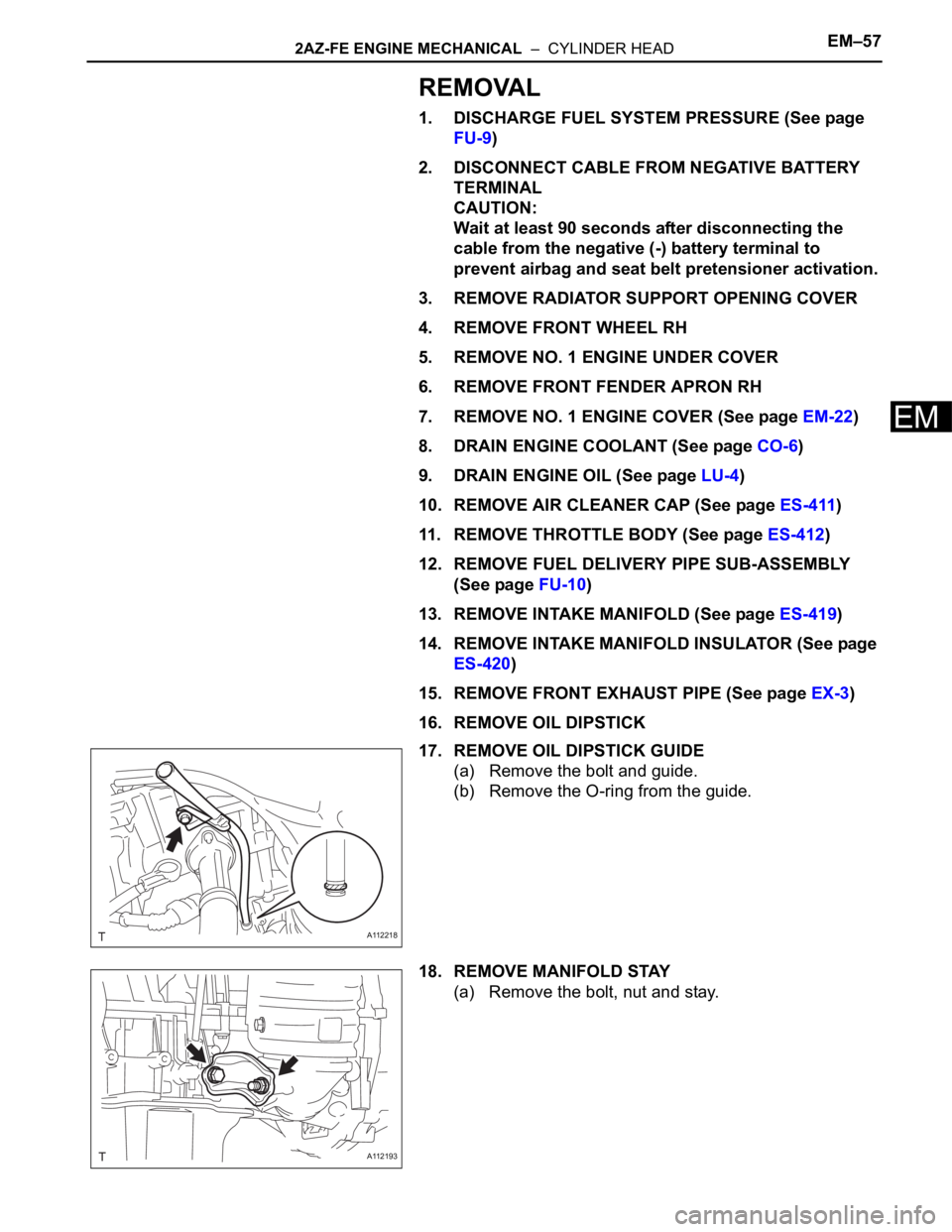
16. REMOVE OIL DIPSTICK
17. REMOVE OIL DIPSTICK GUIDE
(a) Remove the bolt and guide.
(b) Remove the O-ring from the guide.
18. REMOVE MANIFOLD STAY
(a) Remove the bolt, nut and stay.
A112218
A112193
Page 631 of 2000
2AZ-FE ENGINE MECHANICAL – CYLINDER HEADEM–87
EM
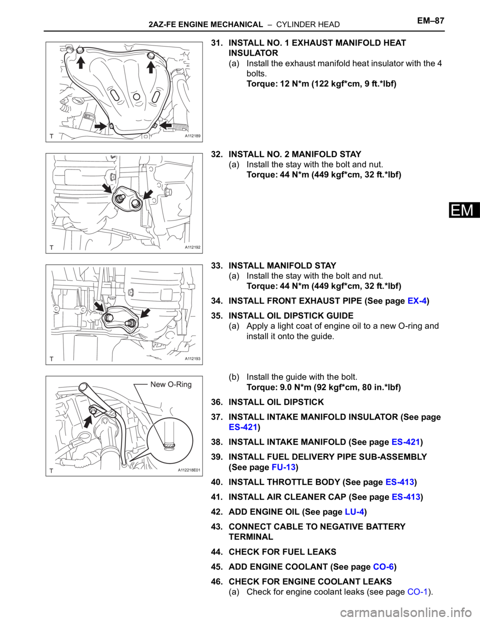
31. INSTALL NO. 1 EXHAUST MANIFOLD HEAT
INSULATOR
(a) Install the exhaust manifold heat insulator with the 4
bolts.
Torque: 12 N*m (122 kgf*cm, 9 ft.*lbf)
32. INSTALL NO. 2 MANIFOLD STAY
(a) Install the stay with the bolt and nut.
Torque: 44 N*m (449 kgf*cm, 32 ft.*lbf)
33. INSTALL MANIFOLD STAY
(a) Install the stay with the bolt and nut.
Torque: 44 N*m (449 kgf*cm, 32 ft.*lbf)
34. INSTALL FRONT EXHAUST PIPE (See page EX-4)
35. INSTALL OIL DIPSTICK GUIDE
(a) Apply a light coat of engine oil to a new O-ring and
install it onto the guide.
(b) Install the guide with the bolt.
Torque: 9.0 N*m (92 kgf*cm, 80 in.*lbf)
36. INSTALL OIL DIPSTICK
37. INSTALL INTAKE MANIFOLD INSULATOR (See page
ES-421)
38. INSTALL INTAKE MANIFOLD (See page ES-421)
39. INSTALL FUEL DELIVERY PIPE SUB-ASSEMBLY
(See page FU-13)
40. INSTALL THROTTLE BODY (See page ES-413)
41. INSTALL AIR CLEANER CAP (See page ES-413)
42. ADD ENGINE OIL (See page LU-4)
43. CONNECT CABLE TO NEGATIVE BATTERY
TERMINAL
44. CHECK FOR FUEL LEAKS
45. ADD ENGINE COOLANT (See page CO-6)
46. CHECK FOR ENGINE COOLANT LEAKS
(a) Check for engine coolant leaks (see page CO-1).
A112189
A112192
A112193
A112218E01