2006 TOYOTA RAV4 battery location
[x] Cancel search: battery locationPage 468 of 2000

ES–142AZ-FE ENGINE CONTROL SYSTEM – SFI SYSTEM
ES
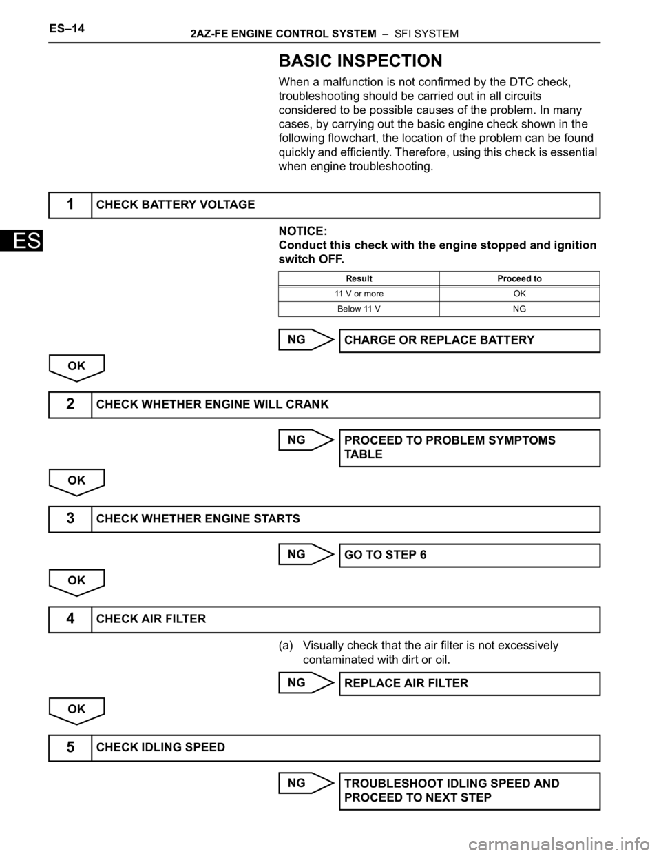
BASIC INSPECTION
When a malfunction is not confirmed by the DTC check,
troubleshooting should be carried out in all circuits
considered to be possible causes of the problem. In many
cases, by carrying out the basic engine check shown in the
following flowchart, the location of the problem can be found
quickly and efficiently. Therefore, using this check is essential
when engine troubleshooting.
NOTICE:
Conduct this check with the engine stopped and ignition
switch OFF.
NG
OK
NG
OK
NG
OK
(a) Visually check that the air filter is not excessively
contaminated with dirt or oil.
NG
OK
NG
1CHECK BATTERY VOLTAGE
Result Proceed to
11 V or more OK
Below 11 V NG
CHARGE OR REPLACE BATTERY
2CHECK WHETHER ENGINE WILL CRANK
PROCEED TO PROBLEM SYMPTOMS
TA B L E
3CHECK WHETHER ENGINE STARTS
GO TO STEP 6
4CHECK AIR FILTER
REPLACE AIR FILTER
5CHECK IDLING SPEED
TROUBLESHOOT IDLING SPEED AND
PROCEED TO NEXT STEP
Page 485 of 2000

2AZ-FE ENGINE CONTROL SYSTEM – SFI SYSTEMES–31
ES
TERMINALS OF ECM
HINT:
The standard normal voltage between each pair of ECM
terminals is shown in the table below. The appropriate
conditions for checking each pair of terminals are also
indicated. The result of checks should be compared with the
standard normal voltage for that pair of terminals, displayed in
the Specified Condition column. The illustration above can be
used as a reference to identify the ECM terminal locations.
A107881E05
Symbols (Terminal No.) Wiring Colors Terminal Descriptions ConditionsSpecified
Conditions
BATT (A9-20) - E1 (B30-104) W - BRBattery (for measuring
battery voltage and for
ECM memory)Always 9 to 14 V
+BM (A9-3) - E1 (B30-104) LG - BRPower source of throttle
actuatorAlways 9 to 14 V
IGSW (A9-28) - E1 (B30-104) B - BR Ignition switch Ignition switch ON 9 to 14 V
+B (A9-2) - E1 (B30-104) B - BR Power source of ECM Ignition switch ON 9 to 14 V
+B2 (A9-1) - E1 (B30-104) B - BR Power source of ECM Ignition switch ON 9 to 14 V
OC1+ (B30-100) - OC1- (B30-
123)BR - LCamshaft timing oil control
valve (OCV)IdlingPulse generation (see
waveform 1)
MREL (A9-44) - E1 (B30-104) O - BR EFI relay Ignition switch ON 9 to 14 V
VG (B30-118) - E2G (B30-116) R - LG Mass air flow meterIdling, Shift lever position P or N, A/
C switch OFF0.5 to 3.0 V
THA (B30-65) - ETHA (B30-88) W - BRIntake air temperature
sensorIdling, Intake air temperature 20
C
(68
F)0.5 to 3.4 V
THW (B30-97) - ETHW (B30-96) GR - BREngine coolant
temperature sensorIdling, Engine coolant temperature
80
C (176F)0.2 to 1.0 V
VCTA (B30-67) - ETA (B30-91) Y - BRPower source of throttle
position sensor (specific
voltage)Ignition switch ON 4.5 to 5.5 V
VTA1 (B30-115) - ETA (B30-91) G - BRThrottle position sensor
(for engine control)Ignition switch ON,
Throttle valve fully closed0.5 to 1.1 V
Ignition switch ON,
Throttle valve fully open3.3 to 4.9 V
VTA2 (B30-114) - ETA (B30-91) L - BRThrottle position sensor
(for sensor malfunction
detection)Ignition switch ON,
Throttle valve fully closed2.1 to 3.1 V
Ignition switch ON,
Throttle valve fully open4.6 to 5.0 V
Page 493 of 2000

2AZ-FE ENGINE CONTROL SYSTEM – SFI SYSTEMES–39
ES
3. 2 TRIP DETECTION LOGIC
When a malfunction is first detected, the malfunction is
temporarily stored in the ECM memory (1st trip). If the
same malfunction is detected during the next
subsequent drive cycle, the MIL is illuminated (2nd trip).
4. FREEZE FRAME DATA
Freeze frame data records the engine conditions (fuel
system, calculated engine load, engine coolant
temperature, fuel trim, engine speed, vehicle speed,
etc.) when malfunctions are detected. When
troubleshooting, freeze frame data can help determine if
the vehicle was moving or stationary, if the engine was
warmed up or not, if the air-fuel ratio was lean or rich,
and other data from the time the malfunction occurred.
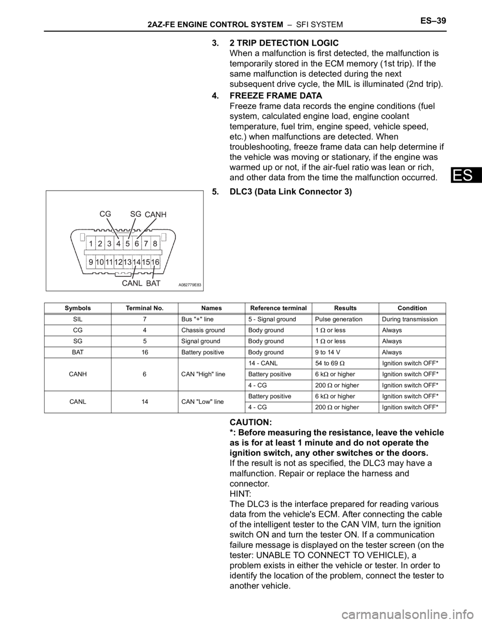
5. DLC3 (Data Link Connector 3)
CAUTION:
*: Before measuring the resistance, leave the vehicle
as is for at least 1 minute and do not operate the
ignition switch, any other switches or the doors.
If the result is not as specified, the DLC3 may have a
malfunction. Repair or replace the harness and
connector.
HINT:
The DLC3 is the interface prepared for reading various
data from the vehicle's ECM. After connecting the cable
of the intelligent tester to the CAN VIM, turn the ignition
switch ON and turn the tester ON. If a communication
failure message is displayed on the tester screen (on the
tester: UNABLE TO CONNECT TO VEHICLE), a
problem exists in either the vehicle or tester. In order to
identify the location of the problem, connect the tester to
another vehicle.
A082779E83
Symbols Terminal No. Names Reference terminal Results Condition
SIL 7 Bus "+" line 5 - Signal ground Pulse generation During transmission
CG 4 Chassis ground Body ground 1
or less Always
SG 5 Signal ground Body ground 1
or less Always
BAT 16 Battery positive Body ground 9 to 14 V Always
CANH 6 CAN "High" line14 - CANL 54 to 69
Ignition switch OFF*
Battery positive 6 k
or higher Ignition switch OFF*
4 - CG 200
or higher Ignition switch OFF*
CANL 14 CAN "Low" lineBattery positive 6 k
or higher Ignition switch OFF*
4 - CG 200
or higher Ignition switch OFF*
Page 540 of 2000

ES–162GR-FE ENGINE CONTROL SYSTEM – SFI SYSTEM
ES
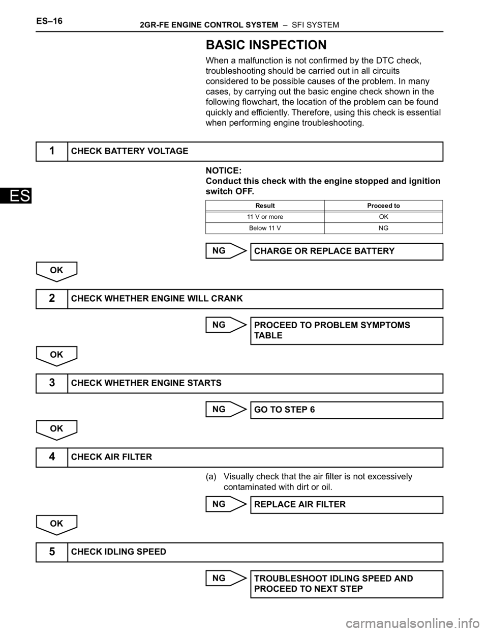
BASIC INSPECTION
When a malfunction is not confirmed by the DTC check,
troubleshooting should be carried out in all circuits
considered to be possible causes of the problem. In many
cases, by carrying out the basic engine check shown in the
following flowchart, the location of the problem can be found
quickly and efficiently. Therefore, using this check is essential
when performing engine troubleshooting.
NOTICE:
Conduct this check with the engine stopped and ignition
switch OFF.
NG
OK
NG
OK
NG
OK
(a) Visually check that the air filter is not excessively
contaminated with dirt or oil.
NG
OK
NG
1CHECK BATTERY VOLTAGE
Result Proceed to
11 V or more OK
Below 11 V NG
CHARGE OR REPLACE BATTERY
2CHECK WHETHER ENGINE WILL CRANK
PROCEED TO PROBLEM SYMPTOMS
TA B L E
3CHECK WHETHER ENGINE STARTS
GO TO STEP 6
4CHECK AIR FILTER
REPLACE AIR FILTER
5CHECK IDLING SPEED
TROUBLESHOOT IDLING SPEED AND
PROCEED TO NEXT STEP
Page 558 of 2000

ES–342GR-FE ENGINE CONTROL SYSTEM – SFI SYSTEM
ES
TERMINALS OF ECM
1. CHECK ECM
(a) Measure the voltage of the ECM connector.
HINT:
The standard normal voltage between each pair of
ECM terminals is shown in the table below. The
appropriate conditions for checking each pair of
terminals are also indicated. The result of checks
should be compared with the standard normal
voltage for that pair of terminals, displayed in the
Specified Condition column. The illustration above
can be used as a reference to identify the ECM
terminal locations.
A107881E05
Symbol (Terminal No.) Wiring Color Terminal Description Condition Specified Condition
BATT (A9-20) - E1 (B30-81) W - BR Battery (for measuring
battery voltage and for
ECM memory)Always 9 to 14 V
+BM (A9-3) - E1 (B30-81) LG - BR Power source of throttle
actuatorAlways 9 to 14 V
IGSW (A9-28) - E1 (B30-81) B - BR Ignition switch Ignition switch ON 9 to 14 V
+B (A9-2) - E1 (B30-81) B - BR Power source of ECM Ignition switch ON 9 to 14 V
+B2 (A9-1) - E1 (B30-81) B - BR Power source of ECM Ignition switch ON 9 to 14 V
OC1+ (B30-58) - OC1- (B30-57) W - B Camshaft timing oil control
valve (OCV)Ignition switch ON Pulse generation (see
waveform 1)
OC2+ (B30-52) - OC2- (B30-51) BR - B Camshaft timing oil control
valve (OCV) (Intake side
(bank 2))Ignition switch ON Pulse generation
(see waveform 1)
OE1+ (B30-56) - OE1- (B30-55) R - LG Camshaft timing oil control
valve (OCV) (Exhaust side
(bank 1))Ignition switch ON Pulse generation
(see waveform 1)
OE2+ (B30-50) - OE2- (B30-49) W - B Camshaft timing oil control
valve (OCV) (Exhaust side
(bank 2))Ignition switch ON Pulse generation
(see waveform 1)
MREL (A9-44) - E1 (B30-81) O - BR EFI relay Ignition switch ON 9 to 14 V
VG (B30-72) - E2G (B30-73) GR - L-G Mass air flow meter Idling, Shift lever position P or N, A/
C switch OFF0.5 to 3.0 V
THA (B30-71) - ETHA (B30-74) P - G-R Intake air temperature
sensorIdling, Intake air temperature 20
C
(68F)0.5 to 3.4 V
Page 567 of 2000

2GR-FE ENGINE CONTROL SYSTEM – SFI SYSTEMES–43
ES
3. 2 TRIP DETECTION LOGIC
When a malfunction is first detected, the malfunction is
temporarily stored in the ECM memory (1st trip). If the
same malfunction is detected during the next
subsequent drive cycle, the MIL is illuminated (2nd trip).
4. FREEZE FRAME DATA
Freeze frame data records the engine conditions (fuel
system, calculated engine load, engine coolant
temperature, fuel trim, engine speed, vehicle speed,
etc.) when malfunctions are detected. When
troubleshooting, freeze frame data can help determine if
the vehicle was moving or stationary, if the engine was
warmed up or not, if the air-fuel ratio was lean or rich,
and other data from the time the malfunction occurred.
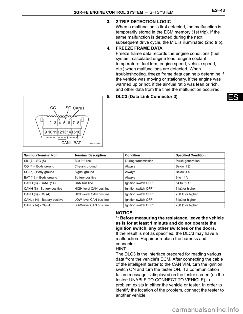
5. DLC3 (Data Link Connector 3)
NOTICE:
*: Before measuring the resistance, leave the vehicle
as is for at least 1 minute and do not operate the
ignition switch, any other switches or the doors.
If the result is not as specified, the DLC3 may have a
malfunction. Repair or replace the harness and
connector.
HINT:
The DLC3 is the interface prepared for reading various
data from the vehicle's ECM. After connecting the cable
of the intelligent tester to the CAN VIM, turn the ignition
switch ON and turn the tester ON. If a communication
failure message is displayed on the tester screen (on the
tester: UNABLE TO CONNECT TO VEHICLE), a
problem exists in either the vehicle or tester. In order to
identify the location of the problem, connect the tester to
another vehicle.
A082779E83
Symbol (Terminal No.) Terminal Description Condition Specified Condition
SIL (7) - SG (5) Bus "+" line During transmission Pulse generation
CG (4) - Body ground Chassis ground Always Below 1
SG (5) - Body ground Signal ground Always Below 1
BAT (16) - Body ground Battery positive Always 9 to 14 V
CANH (6) - CANL (14) CAN bus line Ignition switch OFF* 54 to 69
CANH (6) - Battery positive HIGH-level CAN bus line Ignition switch OFF* 6 k or higher
CANH (6) - CG (4) HIGH-level CAN bus line Ignition switch OFF* 200
or higher
CANL (14) - Battery positive LOW-level CAN bus line Ignition switch OFF* 6 k
or higher
CANL (14) - CG (4) LOW-level CAN bus line Ignition switch OFF* 200
or higher