Page 423 of 2000
STEERING COLUMN – STEERING SYSTEMSR–5
SR
(c) For the following 2steps, carry out the RH and LH
procedures separately.
(1) Draw a line on the tie rod and rack end where it
can easily be seen.
(2) Using a paper gauge, measure the distance
between the tie rod end and the rack end
screw.
(3) Remove the RH and LH boot clips from the
rack boots.
(4) Loosen the RH and LH lock nuts.
(5) Turn the RH and LH rack ends by the same
amount (but in opposite directions) in
accordance with the steering angle.
HINT:
Electronic power steering: 1 turn (360
) of rack
end (1.5 mm (0.059 in.) horizontal movement) -
10.8
of steering angle.
(6) Tighten the RH and LH lock nuts.
Torque: 88 N*m (897 kgf*cm, 65 ft.*lbf)
NOTICE:
Make sure that the difference in length
between the RH and LH tie rod ends and
rack end screws is less than 1.5 mm (0.059
in.).
(7) Install the RH and LH boot clips.
C128833
C128834
Page 1419 of 2000

DRIVE SHAFT – FRONT DRIVE SHAFT ASSEMBLY (for 4WD)DS–65
DS
INSTALLATION
(2005/11-2006/01)
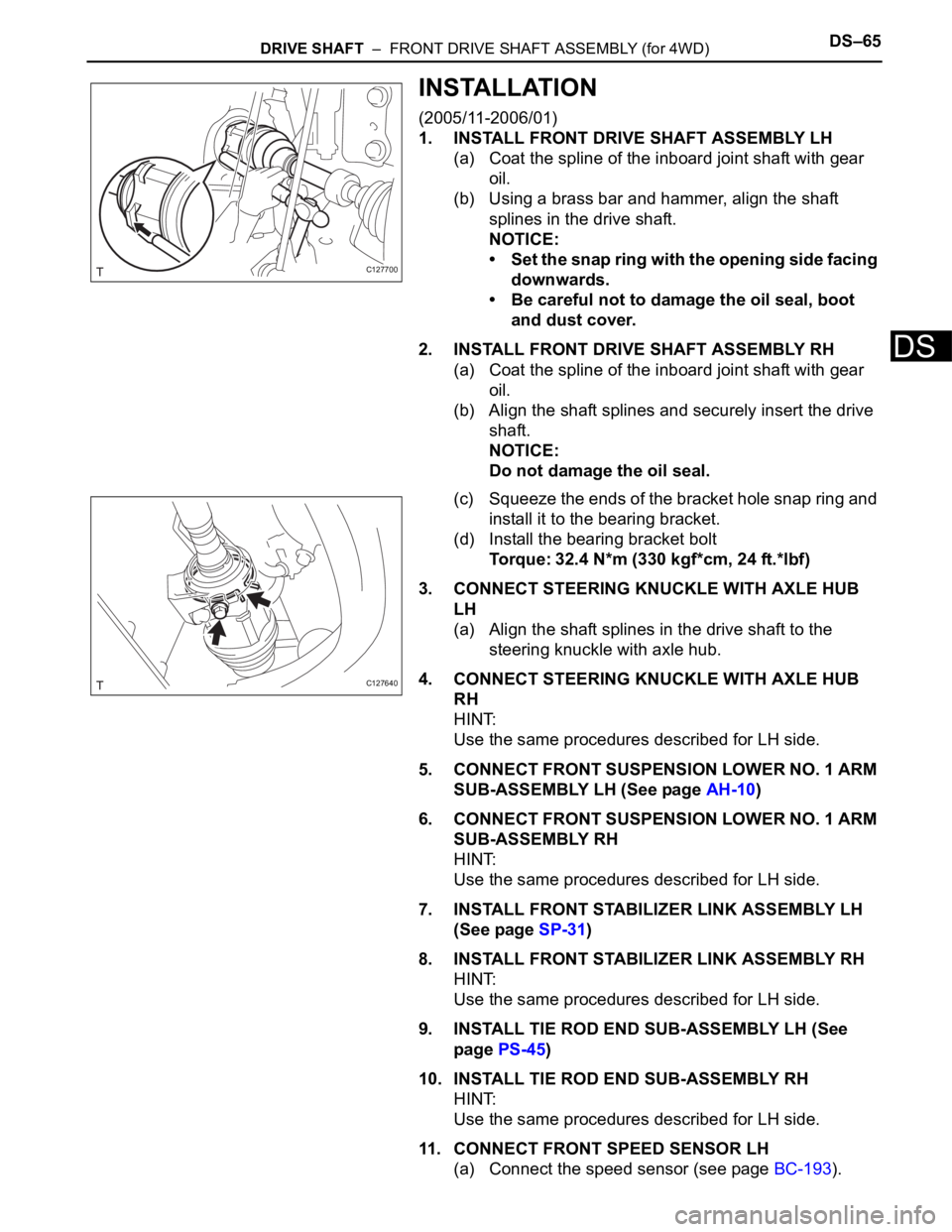
1. INSTALL FRONT DRIVE SHAFT ASSEMBLY LH
(a) Coat the spline of the inboard joint shaft with gear
oil.
(b) Using a brass bar and hammer, align the shaft
splines in the drive shaft.
NOTICE:
• Set the snap ring with the opening side facing
downwards.
• Be careful not to damage the oil seal, boot
and dust cover.
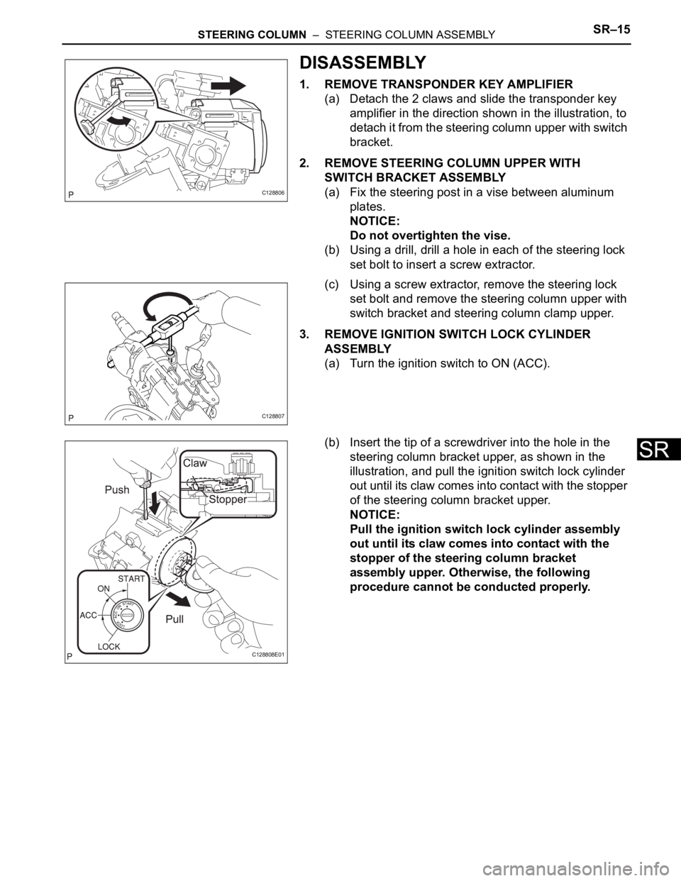
2. INSTALL FRONT DRIVE SHAFT ASSEMBLY RH
(a) Coat the spline of the inboard joint shaft with gear
oil.
(b) Align the shaft splines and securely insert the drive
shaft.
NOTICE:
Do not damage the oil seal.
(c) Squeeze the ends of the bracket hole snap ring and
install it to the bearing bracket.
(d) Install the bearing bracket bolt
Torque: 32.4 N*m (330 kgf*cm, 24 ft.*lbf)
3. CONNECT STEERING KNUCKLE WITH AXLE HUB
LH
(a) Align the shaft splines in the drive shaft to the
steering knuckle with axle hub.
4. CONNECT STEERING KNUCKLE WITH AXLE HUB
RH
HINT:
Use the same procedures described for LH side.
5. CONNECT FRONT SUSPENSION LOWER NO. 1 ARM
SUB-ASSEMBLY LH (See page AH-10)
6. CONNECT FRONT SUSPENSION LOWER NO. 1 ARM
SUB-ASSEMBLY RH
HINT:
Use the same procedures described for LH side.
7. INSTALL FRONT STABILIZER LINK ASSEMBLY LH
(See page SP-31)
8. INSTALL FRONT STABILIZER LINK ASSEMBLY RH
HINT:
Use the same procedures described for LH side.
9. INSTALL TIE ROD END SUB-ASSEMBLY LH (See
page PS-45)
10. INSTALL TIE ROD END SUB-ASSEMBLY RH
HINT:
Use the same procedures described for LH side.
11. CONNECT FRONT SPEED SENSOR LH
(a) Connect the speed sensor (see page BC-193).
C127700
C127640
Page 1599 of 2000

STEERING COLUMN – STEERING COLUMN ASSEMBLYSR–15
SR
DISASSEMBLY
1. REMOVE TRANSPONDER KEY AMPLIFIER
(a) Detach the 2 claws and slide the transponder key
amplifier in the direction shown in the illustration, to
detach it from the steering column upper with switch
bracket.
2. REMOVE STEERING COLUMN UPPER WITH
SWITCH BRACKET ASSEMBLY
(a) Fix the steering post in a vise between aluminum
plates.
NOTICE:
Do not overtighten the vise.
(b) Using a drill, drill a hole in each of the steering lock
set bolt to insert a screw extractor.
(c) Using a screw extractor, remove the steering lock
set bolt and remove the steering column upper with
switch bracket and steering column clamp upper.
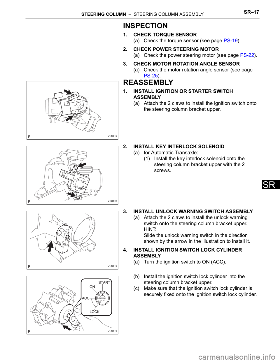
3. REMOVE IGNITION SWITCH LOCK CYLINDER
ASSEMBLY
(a) Turn the ignition switch to ON (ACC).
(b) Insert the tip of a screwdriver into the hole in the
steering column bracket upper, as shown in the
illustration, and pull the ignition switch lock cylinder
out until its claw comes into contact with the stopper
of the steering column bracket upper.
NOTICE:
Pull the ignition switch lock cylinder assembly
out until its claw comes into contact with the
stopper of the steering column bracket
assembly upper. Otherwise, the following
procedure cannot be conducted properly.
C128806
C128807
C128808E01
Page 1600 of 2000
SR–16STEERING COLUMN – STEERING COLUMN ASSEMBLY
SR
(c) Insert the tip of a screwdriver into the hole in the
steering column bracket and tilt it downward, as
shown in the illustration, to disengage the claw of
the ignition switch lock cylinder. Then pull out the
ignition switch lock cylinder.
4. REMOVE UNLOCK WARNING SWITCH ASSEMBLY
(a) Push up the unlock warning switch center portion to
disengage the 2 claws.
HINT:
Slide the unlock warning switch in the direction
shown by the arrow in the illustration to remove it.
5. REMOVE KEY INTERLOCK SOLENOID
(a) for Automatic Transaxle:
(1) Remove the 2 screws and remove the key
interlock solenoid from the steering column
bracket upper.
6. REMOVE IGNITION OR STARTER SWITCH
ASSEMBLY
(a) Detach the 2 claws and remove the ignition (starter)
switch from the steering column bracket upper.
C128809E02
C128810
C128811
C128812
Page 1601 of 2000

STEERING COLUMN – STEERING COLUMN ASSEMBLYSR–17
SR
INSPECTION
1. CHECK TORQUE SENSOR
(a) Check the torque sensor (see page PS-19).
2. CHECK POWER STEERING MOTOR
(a) Check the power steering motor (see page PS-22).
3. CHECK MOTOR ROTATION ANGLE SENSOR
(a) Check the motor rotation angle sensor (see page
PS-25).
REASSEMBLY
1. INSTALL IGNITION OR STARTER SWITCH
ASSEMBLY
(a) Attach the 2 claws to install the ignition switch onto
the steering column bracket upper.
2. INSTALL KEY INTERLOCK SOLENOID
(a) for Automatic Transaxle:
(1) Install the key interlock solenoid onto the
steering column bracket upper with the 2
screws.
3. INSTALL UNLOCK WARNING SWITCH ASSEMBLY
(a) Attach the 2 claws to install the unlock warning
switch onto the steering column bracket upper.
HINT:
Slide the unlock warning switch in the direction
shown by the arrow in the illustration to install it.
4. INSTALL IGNITION SWITCH LOCK CYLINDER
ASSEMBLY
(a) Turn the ignition switch to ON (ACC).
(b) Install the ignition switch lock cylinder into the
steering column bracket upper.
(c) Make sure that the ignition switch lock cylinder is
securely fixed onto the ignition switch lock cylinder.
C128812
C128811
C128815
C128816
Page 1602 of 2000
SR–18STEERING COLUMN – STEERING COLUMN ASSEMBLY
SR
5. INSPECT STEERING LOCK OPERATION
(a) Remove the key and check that the steering lock
function is activated.
(b) Insert the key, turn the ignition switch ON (ACC) and
check that the steering lock function is deactivated.
6. INSTALL STEERING COLUMN UPPER W/ SWITCH
BRACKET ASSEMBLY
(a) Fix the steering column assembly in a vise between
aluminum plates.
NOTICE:
Do not overtighten the vise.
(b) Install the steering column upper with switch bracket
and steering column clamp upper with new steering
lock set bolt, and then tighten the bolts until their
heads come off.
7. INSTALL TRANSPONDER KEY AMPLIFIER
(a) Attach the 2 claws and install the transponder key
amplifier onto the steering column upper with the
switch bracket.
C128817
C128818
C128819
C128820
Page 1603 of 2000

STEERING COLUMN – STEERING COLUMN ASSEMBLYSR–19
SR
INSTALLATION
1. INSTALL STEERING COLUMN ASSEMBLY
(a) Install the steering column onto the instrument panel
reinforcement with the 3 bolts.
Torque: 25 N*m (255 kgf*cm, 18 ft.*lbf)
(b) Connect all the connectors and clamp the wire
harnesses onto the steering column bracket.
2. INSTALL BRAKE PEDAL SUPPORT ASSEMBLY
(a) Install the brake pedal support (see page BR-16).
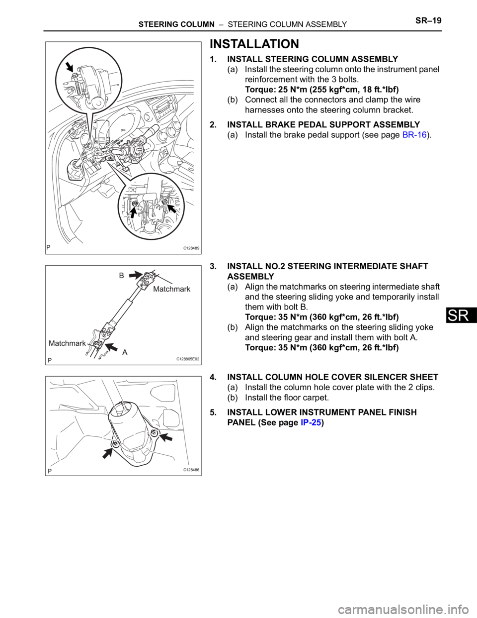
3. INSTALL NO.2 STEERING INTERMEDIATE SHAFT
ASSEMBLY
(a) Align the matchmarks on steering intermediate shaft
and the steering sliding yoke and temporarily install
them with bolt B.
Torque: 35 N*m (360 kgf*cm, 26 ft.*lbf)
(b) Align the matchmarks on the steering sliding yoke
and steering gear and install them with bolt A.
Torque: 35 N*m (360 kgf*cm, 26 ft.*lbf)
4. INSTALL COLUMN HOLE COVER SILENCER SHEET
(a) Install the column hole cover plate with the 2 clips.
(b) Install the floor carpet.
5. INSTALL LOWER INSTRUMENT PANEL FINISH
PANEL (See page IP-25)
C128489
C128805E02
C128486