Page 421 of 2000
STEERING COLUMN – STEERING SYSTEMSR–3
SR
PROBLEM SYMPTOMS TABLE
(2006/01- )
HINT:
Use the table below to help determine the cause of the
problem symptom. The potential causes of the symptoms are
listed in order of probability in the "Suspected Area" column
of the table. Check each symptom by checking the suspected
areas in the order they are listed. Replace parts as
necessary.
Steering system
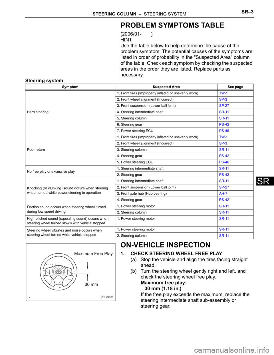
ON-VEHICLE INSPECTION
1. CHECK STEERING WHEEL FREE PLAY
(a) Stop the vehicle and align the tires facing straight
ahead.
(b) Turn the steering wheel gently right and left, and
check the steering wheel free play.
Maximum free play:
30 mm (1.18 in.)
If the free play exceeds the maximum, replace the
steering intermediate shaft sub-assembly or
steering gear.
Symptom Suspected Area See page
Hard steering1. Front tires (Improperly inflated or unevenly worn)TW-1
2. Front wheel alignment (Incorrect)SP-3
3. Front suspension (Lower ball joint)SP-27
4. Steering intermediate shaftSR-11
5. Steering columnSR-11
6. Steering gearPS-42
7. Power steering ECUPS-46
Poor return1. Front tires (Improperly inflated or unevenly worn)TW-1
2. Front wheel alignment (Incorrect)SP-3
3. Steering columnSR-11
4. Steering gearPS-42
5. Power steering ECUPS-46
No free play or excessive play1. Steering intermediate shaftSR-11
2. Steering gearPS-42
Knocking (or clunking) sound occurs when steering
wheel turned while power steering in operation1. Steering intermediate shaftSR-11
2. Front suspension (Lower ball joint)SP-27
3. Front axle hub (Hub bearing)AH-7
4. Steering gearPS-42
Friction sound occurs when steering wheel turned
during low speed driving1. Power steering motorSR-11
2. Steering columnSR-11
High-pitched sound (squealing sound) occurs when
steering wheel turned slowly with vehicle stopped1. Power steering motorSR-11
Steering wheel vibrates and noise occurs when
steering wheel turned while vehicle stopped1. Power steering motorSR-11
2. Steering columnSR-11
C128822E01
Page 649 of 2000
EM–1142AZ-FE ENGINE MECHANICAL – ENGINE ASSEMBLY
EM
58. INSTALL HOOD SUB-ASSEMBLY
(a) Install the hood (see page ED-7).
(b) Adjust the hood (see page ED-5).
59. INSPECT AND ADJUST FRONT WHEEL ALIGNMENT
(a) Inspect and adjust the front wheel alignment (see
page SP-3).
60. PERFORM REGISTRATION
(a) When replacing the engine assembly, perform
vehicle stability control system recognition in ECM
(see page CC-12).
61. RESET MEMORY (for Automatic Transaxle)
(a) When replacing the engine assembly, perform the
RESET MEMORY procedure (A/T initialization) for
U241E (2WD) (see page AX-18) and for U140F
(4WD) (see page AX-18).
Page 688 of 2000
EM–422GR-FE ENGINE MECHANICAL – ENGINE ASSEMBLY
EM
79. INSTALL V-BANK COVER SUB-ASSEMBLY
(a) Attach the 3 clips to install the engine cover.
80. INSTALL RADIATOR SUPPORT OPENING COVER
(a) Install the cover with the 9 clips.
81. ADJUST FRONT WHEEL ALIGNMENT
(a) Adjust the front wheel alignment (see page SP-3).
82. INSPECT IDLE SPEED (See page EM-2)
A137900
A137899
Page 1389 of 2000
DRIVE SHAFT – FRONT DRIVE SHAFT ASSEMBLY (for 2WD)DS–33
DS
12. CONNECT FRONT SPEED SENSOR RH
HINT:
Use the same procedures described for the LH side.
13. INSTALL FRONT AXLE HUB NUT (See page AH-10)
14. INSTALL FRONT WHEEL
Torque: 103 N*m (1,050 kgf*cm, 76 ft.*lbf)
15. ADD AUTOMATIC TRANSAXLE FLUID
(a) Add automatic transaxle fluid for U140F (see page
AX-152).
(b) Add automatic transaxle fluid for U241E (see page
AX-151).
16. CHECK FOR AUTOMATIC TRANSAXLE OIL
LEAKAGE
17. INSPECT AND ADJUST FRONT WHEEL ALIGNMENT
(a) Inspect and adjust the front wheel alignment (see
page SP-3).
INSTALLATION
(2006/01- )
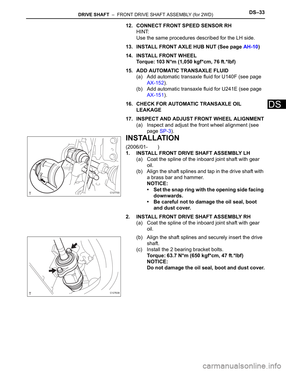
1. INSTALL FRONT DRIVE SHAFT ASSEMBLY LH
(a) Coat the spline of the inboard joint shaft with gear
oil.
(b) Align the shaft splines and tap in the drive shaft with
a brass bar and hammer.
NOTICE:
• Set the snap ring with the opening side facing
downwards.
• Be careful not to damage the oil seal, boot
and dust cover.
2. INSTALL FRONT DRIVE SHAFT ASSEMBLY RH
(a) Coat the spline of the inboard joint shaft with gear
oil.
(b) Align the shaft splines and securely insert the drive
shaft.
(c) Install the 2 bearing bracket bolts.
Torque: 63.7 N*m (650 kgf*cm, 47 ft.*lbf)
NOTICE:
Do not damage the oil seal, boot and dust cover.
C127700
C127638
Page 1390 of 2000
DS–34DRIVE SHAFT – FRONT DRIVE SHAFT ASSEMBLY (for 2WD)
DS
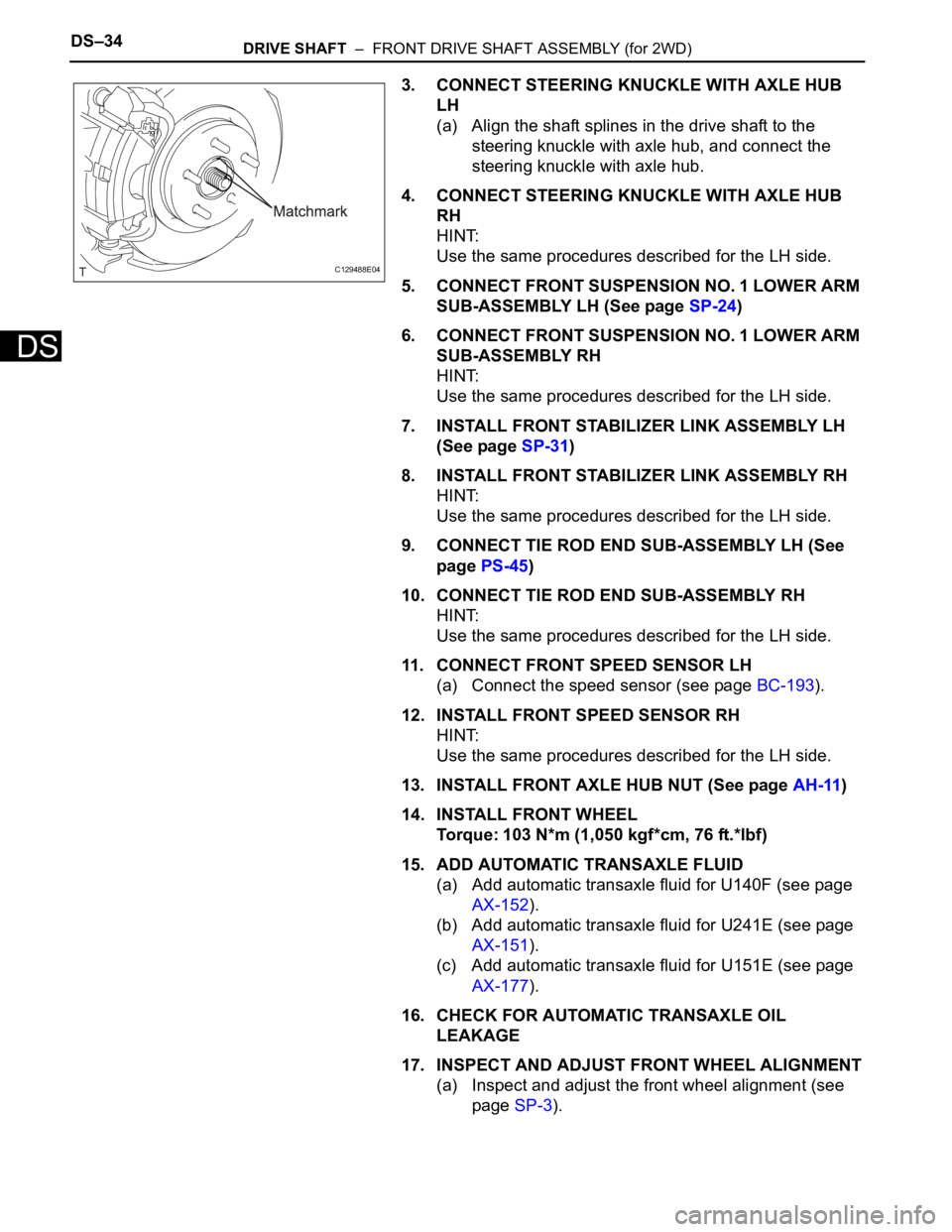
3. CONNECT STEERING KNUCKLE WITH AXLE HUB
LH
(a) Align the shaft splines in the drive shaft to the
steering knuckle with axle hub, and connect the
steering knuckle with axle hub.
4. CONNECT STEERING KNUCKLE WITH AXLE HUB
RH
HINT:
Use the same procedures described for the LH side.
5. CONNECT FRONT SUSPENSION NO. 1 LOWER ARM
SUB-ASSEMBLY LH (See page SP-24)
6. CONNECT FRONT SUSPENSION NO. 1 LOWER ARM
SUB-ASSEMBLY RH
HINT:
Use the same procedures described for the LH side.
7. INSTALL FRONT STABILIZER LINK ASSEMBLY LH
(See page SP-31)
8. INSTALL FRONT STABILIZER LINK ASSEMBLY RH
HINT:
Use the same procedures described for the LH side.
9. CONNECT TIE ROD END SUB-ASSEMBLY LH (See
page PS-45)
10. CONNECT TIE ROD END SUB-ASSEMBLY RH
HINT:
Use the same procedures described for the LH side.
11. CONNECT FRONT SPEED SENSOR LH
(a) Connect the speed sensor (see page BC-193).
12. INSTALL FRONT SPEED SENSOR RH
HINT:
Use the same procedures described for the LH side.
13. INSTALL FRONT AXLE HUB NUT (See page AH-11)
14. INSTALL FRONT WHEEL
Torque: 103 N*m (1,050 kgf*cm, 76 ft.*lbf)
15. ADD AUTOMATIC TRANSAXLE FLUID
(a) Add automatic transaxle fluid for U140F (see page
AX-152).
(b) Add automatic transaxle fluid for U241E (see page
AX-151).
(c) Add automatic transaxle fluid for U151E (see page
AX-177).
16. CHECK FOR AUTOMATIC TRANSAXLE OIL
LEAKAGE
17. INSPECT AND ADJUST FRONT WHEEL ALIGNMENT
(a) Inspect and adjust the front wheel alignment (see
page SP-3).
C129488E04
Page 1420 of 2000
DS–66DRIVE SHAFT – FRONT DRIVE SHAFT ASSEMBLY (for 4WD)
DS
12. CONNECT FRONT SPEED SENSOR RH
HINT:
Use the same procedures described for the LH side.
13. INSTALL FRONT AXLE HUB NUT (See page AH-10)
14. INSTALL FRONT WHEEL
Torque: 103 N*m (1,050 kgf*cm, 76 ft.*lbf)
15. ADD AUTOMATIC TRANSAXLE FLUID
(a) Add automatic transaxle fluid for U140F (see page
AX-152).
(b) Add automatic transaxle fluid for U241E (see page
AX-151).
16. CHECK FOR AUTOMATIC TRANSAXLE FLUID
LEAKAGE
17. INSPECT AND ADJUST FRONT WHEEL ALIGNMENT
(a) Inspect and adjust front wheel alignment (see page
SP-3).
INSTALLATION
(2006/01- )
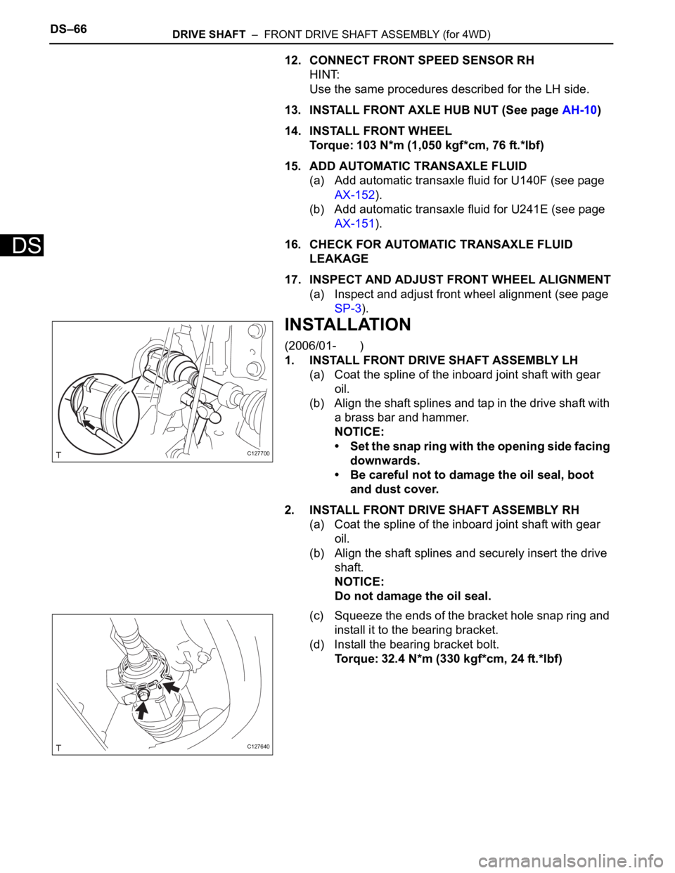
1. INSTALL FRONT DRIVE SHAFT ASSEMBLY LH
(a) Coat the spline of the inboard joint shaft with gear
oil.
(b) Align the shaft splines and tap in the drive shaft with
a brass bar and hammer.
NOTICE:
• Set the snap ring with the opening side facing
downwards.
• Be careful not to damage the oil seal, boot
and dust cover.
2. INSTALL FRONT DRIVE SHAFT ASSEMBLY RH
(a) Coat the spline of the inboard joint shaft with gear
oil.
(b) Align the shaft splines and securely insert the drive
shaft.
NOTICE:
Do not damage the oil seal.
(c) Squeeze the ends of the bracket hole snap ring and
install it to the bearing bracket.
(d) Install the bearing bracket bolt.
Torque: 32.4 N*m (330 kgf*cm, 24 ft.*lbf)
C127700
C127640
Page 1421 of 2000
DRIVE SHAFT – FRONT DRIVE SHAFT ASSEMBLY (for 4WD)DS–67
DS
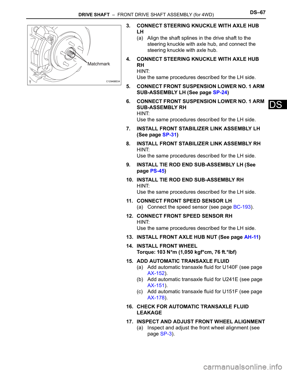
3. CONNECT STEERING KNUCKLE WITH AXLE HUB
LH
(a) Align the shaft splines in the drive shaft to the
steering knuckle with axle hub, and connect the
steering knuckle with axle hub.
4. CONNECT STEERING KNUCKLE WITH AXLE HUB
RH
HINT:
Use the same procedures described for the LH side.
5. CONNECT FRONT SUSPENSION LOWER NO. 1 ARM
SUB-ASSEMBLY LH (See page SP-24)
6. CONNECT FRONT SUSPENSION LOWER NO. 1 ARM
SUB-ASSEMBLY RH
HINT:
Use the same procedures described for the LH side.
7. INSTALL FRONT STABILIZER LINK ASSEMBLY LH
(See page SP-31)
8. INSTALL FRONT STABILIZER LINK ASSEMBLY RH
HINT:
Use the same procedures described for the LH side.
9. INSTALL TIE ROD END SUB-ASSEMBLY LH (See
page PS-45)
10. INSTALL TIE ROD END SUB-ASSEMBLY RH
HINT:
Use the same procedures described for the LH side.
11. CONNECT FRONT SPEED SENSOR LH
(a) Connect the speed sensor (see page BC-193).
12. CONNECT FRONT SPEED SENSOR RH
HINT:
Use the same procedures described for the LH side.
13. INSTALL FRONT AXLE HUB NUT (See page AH-11)
14. INSTALL FRONT WHEEL
Torque: 103 N*m (1,050 kgf*cm, 76 ft.*lbf)
15. ADD AUTOMATIC TRANSAXLE FLUID
(a) Add automatic transaxle fluid for U140F (see page
AX-152).
(b) Add automatic transaxle fluid for U241E (see page
AX-151).
(c) Add automatic transaxle fluid for U151F (see page
AX-178).
16. CHECK FOR AUTOMATIC TRANSAXLE FLUID
LEAKAGE
17. INSPECT AND ADJUST FRONT WHEEL ALIGNMENT
(a) Inspect and adjust the front wheel alignment (see
page SP-3).
C129488E04
Page 1453 of 2000
AH–12AXLE – FRONT AXLE HUB
AH
(b) Using a chisel and hammer, stake the hub nut.
11. INSTALL FRONT WHEEL
Torque: 103 N*m (1,050 kgf*cm, 6 ft.*lbf)
12. INSPECT AND ADJUST FRONT WHEEL ALIGNMENT
(a) Inspect and adjust the wheel alignment (see page
SP-3).
13. CONNECT CABLE TO NEGATIVE BATTERY
TERMINAL
14. CHECK SPEED SENSOR SIGNAL
(a) Check the speed sensor signal (see page BC-44).
C129484