Page 13 of 2000
ENGINE - 2AZ-FE ENGINE
01NEG35Y
Throttle Body
To H e a t e r C o r e
To R a d i a t o r
Thermostat
From Radiator Wa t e r P u m pBypass Passage
01NEG59Y
Bypass PassageCylinder Head
Wa t e r P u m p
Cylinder Block
Thermostat
Reservoir
Ta n k
RadiatorThrottle
BodyHeater Core EG-16
COOLING SYSTEM
The cooling system uses a pressurized forced-circulation system with pressurized reservoir tank.
A thermostat with a bypass valve is located on the water inlet housing to maintain suitable temperature
distribution in the cooling system.
An aluminum radiator core is used for weight reduction.
The flow of the engine coolant makes a U-turn in the cylinder block to ensure a smooth flow of the engine
coolant. In addition, a bypass passage is enclosed in the cylinder head and the cylinder block.
Warm water from the engine is sent to the throttle body to prevent freeze-up.
The TOYOTA genuine Super Long Life Coolant (SLLC) is used.
System Diagram
Page 27 of 2000

ENGINE - 2AZ-FE ENGINE EG-30
ENGINE CONTROL SYSTEM
1. General
The engine control system for the 2AZ-FE engine has the following systems.
System
Outline
SFI
Sequential Multiport
Fuel InjectionAn L-type SFI system directly detects the intake air volume with a hot-wire
type mass air flow meter.
The fuel injection system is a sequential multiport fuel injection system.
ESA
Electronic Spark
AdvanceIgnition timing is determined by the ECM based on signals from various sensors.
The ECM corrects ignition timing in response to engine knocking.
ETCS-i
Electronic
Optimally controls the throttle valve opening in accordance with the amount of
accelerator pedal effort and the condition of the engine and the vehicle.
Electronic
Throttle Control
System-intelligent
(See page-43)A linkless-type is used, without an accelerator cable.
An accelerator pedal position sensor is provided on the accelerator pedal.
A non-contact type throttle position sensor and accelerator pedal position
sensor are used.
VVT-i
Va r i a b l e Va l v e
Timing-intelligent
(See page EG-48)
Controls the intake camshaft to an optimal valve timing in accordance with the
engine condition.
Air-fuel Ratio
Sensor, Oxygen
Sensor Heater
ControlMaintains the temperature of the air-fuel ratio sensor or oxygen sensor at an
appropriate level to realize accuracy of detection of the oxygen concentration in
the exhaust gas.
Air Conditioning
Cut-off ControlBy turning the air conditioning compressor ON or OFF in accordance with the
engine condition, drivability is maintained.
Cooling Fan Control
(See page EG-52)Radiator cooling fan operation is controlled by signals from ECM based on the
engine coolant temperature sensor signal and the condition of the air
conditioning operation.
Fuel Pump Control
(See page EG-53)Fuel pump operation is controlled by signal from the ECM.
The fuel pump is stopped when the SRS driver’s and front passenger’s airbags
are deployed.
Evapotative Emission
The ECM controls the purge flow of evaporative emissions (HC) in the canister
in accordance with engine conditions.
Evapotative Emission
Control
(See page EG-54)Approximately five hours after the ignition switch has been turned OFF, the
ECM operates the canister pump module to detect any evaporative emission
leakage occurring in the EVAP (evaporative emission) control system through
changes in the 0.02 in. leak pressure.
Charging Control
(See page EG-65)The ECM regulates the charging voltage of the generator in accordance with the
driving conditions and the charging state of the battery.
(Continued)
Page 84 of 2000

ENGINE - 2GR-FE ENGINE
285EG27
Air Bleeder PlugTo Throttle Body
From Throttle Body
To H e a t e r
From Heater
To Radiator
From Radiator Thermostat
Opening Temperature:
80 - 84
C (176 - 183F)
01MEG35Y
ThermostatBypass Pipe
Heater Return Pipe
Air Bleeder Plug
Cylinder Head
Cylinder Block
Wa t e r P u m p
Radiator
Throttle
Body
Heater
Reservoir
Ta n k
EG-88
COOLING SYSTEM
1. General
The cooling system is a pressurized, forced-circulation type.
A thermostat with a bypass valve is located on the water inlet housing to maintain suitable temperature
distribution in the cooling system.
A cooling fan control system in which the ECM optimally controls cooling fan speed is used. For details,
see page EG-129.
An air bleeder plug is provided on the water inlet assembly to improve the efficiency of changing the
engine coolant. For details, refer to the 2006 RAV4 Repair Manual (Pub. No. RM01M1U).
The TOYOTA genuine SLLC (Super Long Life Coolant) is used for the engine coolant.
System Diagram
Page 172 of 2000
PP–22PREPARATION – 2AZ-FE COOLING
PP
EQUIPMENT
Ohmmeter -
Radiator cap tester -
Thermometer -
To r q u e w r e n c h -
Slide calipers -
Heater -
Page 182 of 2000

MAINTENANCE – UNDER HOODMA–7
MA
GENERAL MAINTENANCE
(2006/01- )
1. GENERAL NOTES
• Maintenance requirements vary depending on the
country.
• Check the maintenance schedule in the owner's
manual supplement.
• Following the maintenance schedule is mandatory.
• Determine the appropriate time to service the vehicle
using either miles driven or time elapsed, whichever
reaches the specification first.
• Maintain similar intervals between periodic
maintenance, unless otherwise noted.
• Failing to check each vehicle part could lead to poor
engine performance and increase exhaust emissions.
2. WINDSHIELD WASHER FLUID
(a) Check that there is sufficient fluid in the tank.
3. ENGINE COOLANT LEVEL
(a) Check that the coolant level is between the "FULL"
and "LOW" lines on the see-through reservoir.
4. RADIATOR AND HOSES
(a) Check that the front of the radiator is clean and not
blocked by leaves, dirt or bugs.
(b) Check the hoses for cracks, kinks, rot or loose
connections.
5. BATTERY ELECTROLYTE LEVEL
(a) Check that the electrolyte level of all the battery
cells is between the upper and lower level lines on
the case.
HINT:
If the electrolyte level is difficult to see, lightly shake
the vehicle.
6. BRAKE FLUID LEVEL
(a) Check that the brake fluid levels are near the upper
level lines on the see-through reservoirs.
7. ENGINE DRIVE BELT
(a) Check the drive belt for fraying, cracks, wear or
oiliness.
8. ENGINE OIL LEVEL
(a) Check the level on the dipstick with the engine
stopped.
9. AUTOMATIC TRANSAXLE FLUID LEVEL
10. EXHAUST SYSTEM
(a) Check for unusual exhaust sounds or abnormal
exhaust fumes. Inspect the cause and repair it.
Type See procedures
U151E See page AX-126
U151F See page AX-126
Page 195 of 2000

2AZ-FE ENGINE MECHANICAL – DRIVE BELTEM–7
EM
REMOVAL
1. REMOVE RADIATOR SUPPORT OPENING COVER
2. REMOVE FRONT WHEEL RH
3. REMOVE FRONT FENDER APRON RH
4. REMOVE FRONT SUSPENSION MEMBER
REINFORCEMENT RH
(a) Remove the 4 bolts and reinforcement RH.
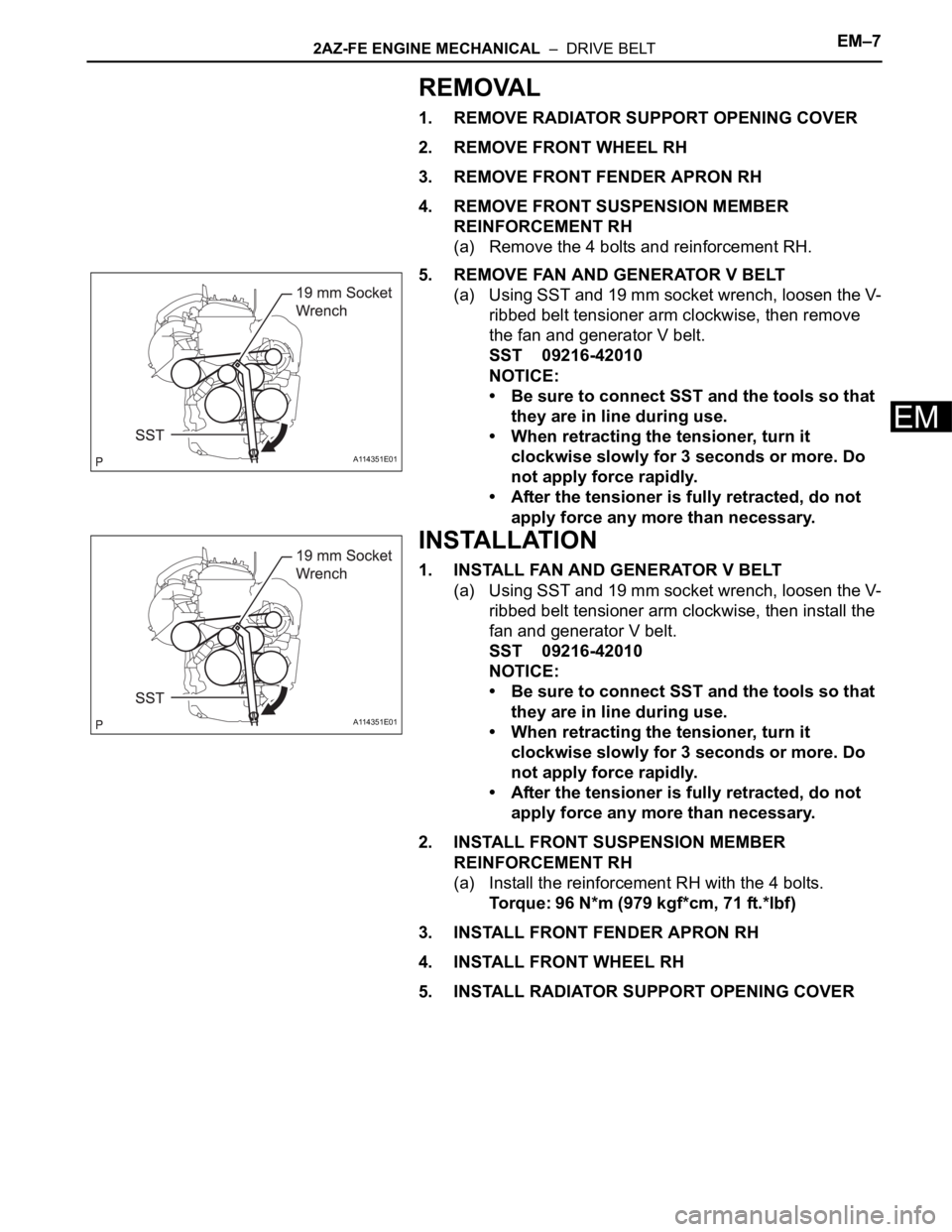
5. REMOVE FAN AND GENERATOR V BELT
(a) Using SST and 19 mm socket wrench, loosen the V-
ribbed belt tensioner arm clockwise, then remove
the fan and generator V belt.
SST 09216-42010
NOTICE:
• Be sure to connect SST and the tools so that
they are in line during use.
• When retracting the tensioner, turn it
clockwise slowly for 3 seconds or more. Do
not apply force rapidly.
• After the tensioner is fully retracted, do not
apply force any more than necessary.
INSTALLATION
1. INSTALL FAN AND GENERATOR V BELT
(a) Using SST and 19 mm socket wrench, loosen the V-
ribbed belt tensioner arm clockwise, then install the
fan and generator V belt.
SST 09216-42010
NOTICE:
• Be sure to connect SST and the tools so that
they are in line during use.
• When retracting the tensioner, turn it
clockwise slowly for 3 seconds or more. Do
not apply force rapidly.
• After the tensioner is fully retracted, do not
apply force any more than necessary.
2. INSTALL FRONT SUSPENSION MEMBER
REINFORCEMENT RH
(a) Install the reinforcement RH with the 4 bolts.
Torque: 96 N*m (979 kgf*cm, 71 ft.*lbf)
3. INSTALL FRONT FENDER APRON RH
4. INSTALL FRONT WHEEL RH
5. INSTALL RADIATOR SUPPORT OPENING COVER
A114351E01
A114351E01
Page 197 of 2000
EM–222GR-FE ENGINE MECHANICAL – ENGINE ASSEMBLY
EM
15. REMOVE RADIATOR SUPPORT OPENING COVER
(a) Remove the 9 clips and cover.
16. REMOVE BATTERY CLAMP SUB-ASSEMBLY
(a) Remove the bolt and loosen the nut.
(b) Detach the 2 wire harness clamps.
(c) Detach the hook of the battery clamp from the
battery bracket front, and then remove the battery
clamp.
17. REMOVE BATTERY
18. REMOVE FRONT BATTERY BRACKET
(a) Detach the 2 wire harness clamps.
(b) Remove the 4 bolts and front bracket.
19. REMOVE BATTERY BRACKET REINFORCEMENT
(a) Remove the 2 bolts and bracket reinforcement.
A137899
A124917E01
A124918
A124919
Page 198 of 2000

2GR-FE ENGINE MECHANICAL – ENGINE ASSEMBLYEM–23
EM
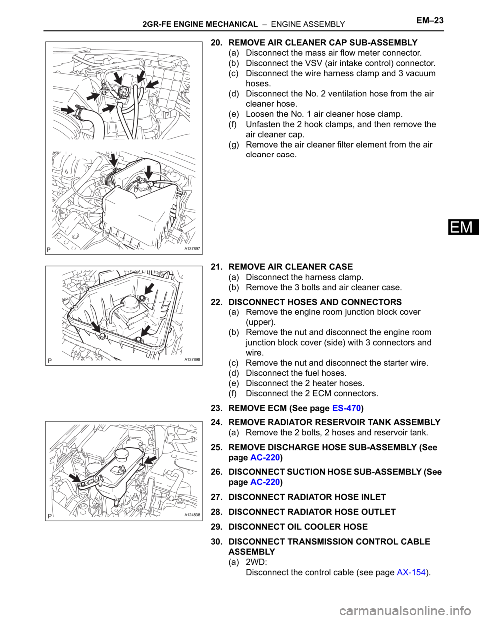
20. REMOVE AIR CLEANER CAP SUB-ASSEMBLY
(a) Disconnect the mass air flow meter connector.
(b) Disconnect the VSV (air intake control) connector.
(c) Disconnect the wire harness clamp and 3 vacuum
hoses.
(d) Disconnect the No. 2 ventilation hose from the air
cleaner hose.
(e) Loosen the No. 1 air cleaner hose clamp.
(f) Unfasten the 2 hook clamps, and then remove the
air cleaner cap.
(g) Remove the air cleaner filter element from the air
cleaner case.
21. REMOVE AIR CLEANER CASE
(a) Disconnect the harness clamp.
(b) Remove the 3 bolts and air cleaner case.
22. DISCONNECT HOSES AND CONNECTORS
(a) Remove the engine room junction block cover
(upper).
(b) Remove the nut and disconnect the engine room
junction block cover (side) with 3 connectors and
wire.
(c) Remove the nut and disconnect the starter wire.
(d) Disconnect the fuel hoses.
(e) Disconnect the 2 heater hoses.
(f) Disconnect the 2 ECM connectors.
23. REMOVE ECM (See page ES-470)
24. REMOVE RADIATOR RESERVOIR TANK ASSEMBLY
(a) Remove the 2 bolts, 2 hoses and reservoir tank.
25. REMOVE DISCHARGE HOSE SUB-ASSEMBLY (See
page AC-220)
26. DISCONNECT SUCTION HOSE SUB-ASSEMBLY (See
page AC-220)
27. DISCONNECT RADIATOR HOSE INLET
28. DISCONNECT RADIATOR HOSE OUTLET
29. DISCONNECT OIL COOLER HOSE
30. DISCONNECT TRANSMISSION CONTROL CABLE
ASSEMBLY
(a) 2WD:
Disconnect the control cable (see page AX-154).
A137897
A137898
A124838