Page 512 of 2000
ET–6EXTERIOR – FRONT BUMPER
ET
8. REMOVE FRONT BUMPER RETAINER
(a) Remove the bolt and retainer.
9. REMOVE FRONT BUMPER REINFORCEMENT SUB-
ASSEMBLY
(a) Detach 5 clamps and remove the wire harness.
(b) Remove the 8 bolts and reinforcement.
10. REMOVE FRONT BUMPER SIDE RETAINER LH
(a) Remove the bolt.
(b) Using a screwdriver, detach the clip and remove
the bumper side retainer.
HINT:
Tape the screwdriver tip before use.
11. REMOVE FRONT BUMPER SIDE RETAINER RH
HINT:
Use the same procedures described for the LH side.
DISASSEMBLY
1. REMOVE RADIATOR GRILLE SUB-ASSEMBLY
(a) Remove the 4 bolts and 4 nuts.
B139376
B137681
B137682
B127934
B135282
Page 513 of 2000
EXTERIOR – FRONT BUMPERET–7
ET
(b) Detach the 6 claws and remove the radiator grille.
2. REMOVE NO. 1 RADIATOR GRILLE LOWER
(a) Detach the 18 claws and remove the radiator grille.
3. REMOVE NO. 2 RADIATOR GRILLE LOWER
(a) Detach the 16 claws and remove the radiator grille.
4. REMOVE FRONT BUMPER ARM HOLE COVER LH
(a) Detach the 2 claws and disconnect the arm hole
cover.
(b) Remove the hook and bumper arm hole cover.
5. REMOVE FRONT BUMPER ARM HOLE COVER RH
(a) Use the same procedures described for the LH side.
B136794
B135283
B135284
B127941
Page 515 of 2000
EXTERIOR – FRONT BUMPERET–9
ET
3. INSTALL FRONT BUMPER HOLE COVER LH (w/o
Fog Light)
(a) Install the bumper hole cover with the fog light
mounting bracket and 3 bolts.
4. INSTALL FRONT BUMPER HOLE COVER RH (w/o
Fog Light)
HINT:
Use the same procedures described for the LH side.
5. INSTALL FOG LIGHT ASSEMBLY LH
(a) Install the fog light mounting bracket with the 3 bolts.
(b) Install the fog light with the screw.
6. INSTALL FOG LIGHT ASSEMBLY RH
HINT:
Use the same procedures described for the LH side.
7. INSTALL FRONT BUMPER ARM HOLE COVER LH
(a) Install the hook.
(b) Attach the 2 claws and install the hole cover.
8. INSTALL FRONT BUMPER ARM HOLE COVER RH
HINT:
Use the same procedures described for the LH side.
9. INSTALL NO. 2 RADIATOR GRILLE LOWER
(a) Install the radiator grille and attach the 16 claws.
10. INSTALL NO. 1 RADIATOR GRILLE LOWER
(a) Install the radiator grille and attach the 18 claws.
B133194
B133193
B127941
B135284
B135283
Page 516 of 2000
ET–10EXTERIOR – FRONT BUMPER
ET
11. INSTALL RADIATOR GRILLE SUB-ASSEMBLY
(a) Install the radiator grille with the 6 claws.
(b) Install the 4 bolts and 4 nuts.
B136794
B135282
Page 579 of 2000
EM–222AZ-FE ENGINE MECHANICAL – TIMING CHAIN
EM
REMOVAL
1. DISCONNECT CABLE FROM NEGATIVE BATTERY
TERMINAL
CAUTION:
Wait at least 90 seconds after disconnecting the
cable from the negative (-) battery terminal to
prevent airbag and seat belt pretensioner activation.
2. REMOVE RADIATOR SUPPORT OPENING COVER
3. REMOVE FRONT WHEEL RH
4. REMOVE NO. 1 ENGINE UNDER COVER
5. REMOVE FRONT FENDER APRON RH
6. REMOVE NO. 1 ENGINE COVER
(a) Remove the 2 nuts and cover.
7. DRAIN ENGINE OIL (See page LU-4)
8. REMOVE FRONT EXHAUST PIPE (See page EX-3)
9. REMOVE FRONT SUSPENSION MEMBER
REINFORCEMENT RH (See page EM-6)
10. REMOVE FAN AND GENERATOR V BELT (See page
EM-6)
11. REMOVE GENERATOR ASSEMBLY (See page CH-9)
12. REMOVE RADIATOR RESERVOIR
(a) Remove the 2 bolts and radiator reservoir.
13. REMOVE ENGINE MOUNTING INSULATOR RH
(a) Remove the bolt of the wire harness protector.
(b) Disconnect the 2 clamps of the engine wire.
A112206
A124838
A098189E02
Page 599 of 2000
EM–422AZ-FE ENGINE MECHANICAL – TIMING CHAIN
EM
(b) Connect the 2 clamps of the engine wire.
(c) Install the wire harness protector with the bolt.
20. INSTALL ENGINE MOUNTING INSULATOR FR
(a) Install the engine mounting insulator FR with the 2
bolts.
Torque: 95 N*m (969 kgf*cm, 70 ft.*lbf)
(b) Install the through bolt and nut.
Torque: 145 N*m (1,479 kgf*cm, 107 ft.*lbf)
HINT:
Install the bolt which is used to secure the front
engine mounting bracket FR.
21. INSTALL RADIATOR RESERVOIR
(a) Install the radiator reservoir with the 2 bolts.
Torque: 5.0 N*m (51 kgf*cm, 44 in.*lbf)
22. INSTALL GENERATOR ASSEMBLY (See page CH-15)
23. INSTALL FAN AND GENERATOR V BELT (See page
EM-7)
24. INSTALL FRONT SUSPENSION MEMBER
REINFORCEMENT RH (See page EM-7)
25. INSTALL FRONT EXHAUST PIPE (See page EX-4)
26. ADD ENGINE OIL (See page LU-4)
27. CONNECT CABLE TO NEGATIVE BATTERY
TERMINAL
28. CHECK FOR ENGINE OIL LEAKS
29. CHECK FOR EXHAUST GAS LEAKS
A098189E01
A124840
A124839E02
A124838
Page 600 of 2000
2AZ-FE ENGINE MECHANICAL – TIMING CHAINEM–43
EM
30. INSTALL NO. 1 ENGINE COVER
(a) Install the engine cover with the 2 nuts.
Torque: 7.0 N*m (71 kgf*cm, 62 in.*lbf)
31. INSTALL FRONT FENDER APRON RH
32. INSTALL NO. 1 ENGINE UNDER COVER
33. INSTALL FRONT WHEEL RH
34. INSTALL RADIATOR SUPPORT OPENING COVER
A112206
Page 601 of 2000

2AZ-FE ENGINE MECHANICAL – CYLINDER HEADEM–57
EM
REMOVAL
1. DISCHARGE FUEL SYSTEM PRESSURE (See page
FU-9)
2. DISCONNECT CABLE FROM NEGATIVE BATTERY
TERMINAL
CAUTION:
Wait at least 90 seconds after disconnecting the
cable from the negative (-) battery terminal to
prevent airbag and seat belt pretensioner activation.
3. REMOVE RADIATOR SUPPORT OPENING COVER
4. REMOVE FRONT WHEEL RH
5. REMOVE NO. 1 ENGINE UNDER COVER
6. REMOVE FRONT FENDER APRON RH
7. REMOVE NO. 1 ENGINE COVER (See page EM-22)
8. DRAIN ENGINE COOLANT (See page CO-6)
9. DRAIN ENGINE OIL (See page LU-4)
10. REMOVE AIR CLEANER CAP (See page ES-411)
11. REMOVE THROTTLE BODY (See page ES-412)
12. REMOVE FUEL DELIVERY PIPE SUB-ASSEMBLY
(See page FU-10)
13. REMOVE INTAKE MANIFOLD (See page ES-419)
14. REMOVE INTAKE MANIFOLD INSULATOR (See page
ES-420)
15. REMOVE FRONT EXHAUST PIPE (See page EX-3)
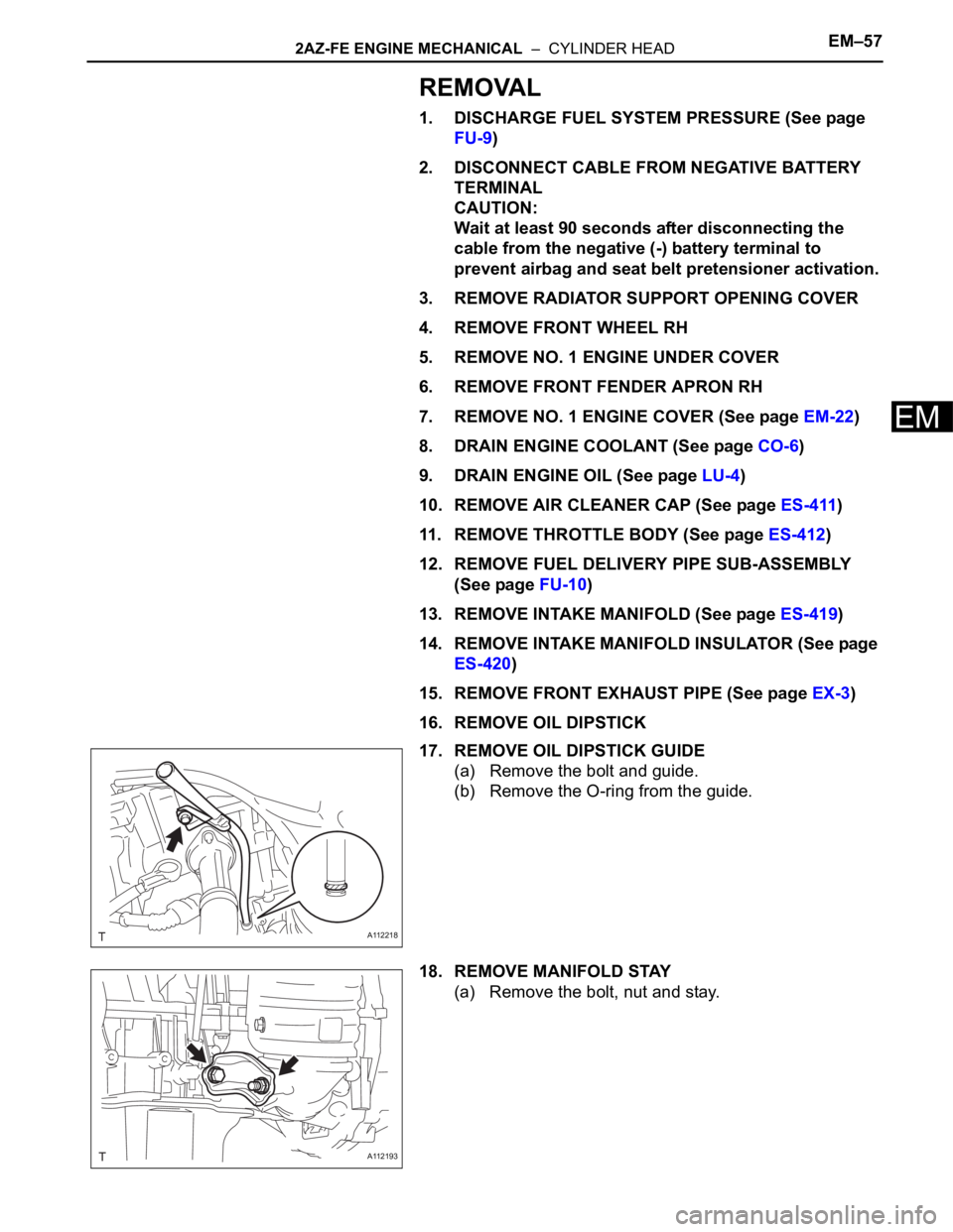
16. REMOVE OIL DIPSTICK
17. REMOVE OIL DIPSTICK GUIDE
(a) Remove the bolt and guide.
(b) Remove the O-ring from the guide.
18. REMOVE MANIFOLD STAY
(a) Remove the bolt, nut and stay.
A112218
A112193