Page 252 of 2000
PREPARATION – 2AZ-FE ENGINE MECHANICALPP–7
PP
EQUIPMENT
V-block -
Piston ring compressor -
Piston ring expander -
Valve seat cutter -
Feeler gauge -
CO/HC meter -
Connecting rod aligner -
Cylinder gauge -
Micrometer -
Precision straight edge -
Radiator cap tester -
Steel square -
Tachometer -
Torque wrench -
Vernier calipers -
Dial indicator with magnetic base -
Alignment tester -
toe-in gauge -
Spring tension gauge -
Slide calipers -
Sandpaper (#400) -
Piston heater -
Wooden block -
Plastigage -
Angle gauge -
Timing light -
Page 257 of 2000
PP–10PREPARATION – 2GR-FE ENGINE MECHANICAL
PP
EQUIPMENT
Alignment tester -
Angle gauge -
Brass bar -
Caliper gauge -
Chain block -
Compression gauge -
CO/HC meter -
Connecting rod aligner -
Cylinder gauge -
Dial indicator with magnetic base -
Engine stand -
Feeler gauge -
Gasket scraper -
Magnetic finger -
Micrometer -
Needle-nose pliers -
No. 1 engine hanger -
No. 2 engine hanger -
Pin hole grinder -
Piston ring compressor -
Piston ring expander -
Piston heater -
Plastigage -
Plastic-faced hammer -
Press -
Radiator cap tester -
Reamer (5.5 mm) -
Ridge reamer -
Rod aligner -
Sandpaper (#400) -
Slide calipers -
Straightedge -
Spring scale -
Spring tension gauge -
Steel square -
Tachometer -
Timing light -
Toe-in gauge -
To r q u e w r e n c h -
Valve seat cutter -
V-block -
Vernier calipers -
Vise -
Wooden block -
Page 299 of 2000
PREPARATION – 2GR-FE COOLINGPP–23
PP
EQUIPMENT
Ohmmeter -
Radiator cap tester -
Thermometer -
Torque wrench -
Side calipers -
Heater -
Page 379 of 2000

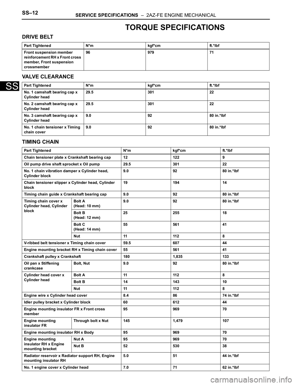
SS–12SERVICE SPECIFICATIONS – 2AZ-FE ENGINE MECHANICAL
SS
TORQUE SPECIFICATIONS
DRIVE BELT
VALVE CLEARANCE
TIMING CHAIN
Part Tightened N*m kgf*cm ft.*lbf
Front suspension member
reinforcement RH x Front cross
member, Front suspension
crossmember96 979 71
Part Tightened N*m kgf*cm ft.*lbf
No. 1 camshaft bearing cap x
Cylinder head29.5 301 22
No. 2 camshaft bearing cap x
Cylinder head29.5 301 22
No. 3 camshaft bearing cap x
Cylinder head9.0 92 80 in.*lbf
No. 1 chain tensioner x Timing
chain cover9.0 92 80 in.*lbf
Part Tightened N*m kgf*cm ft.*lbf
Chain tensioner plate x Crankshaft bearing cap 12 122 9
Oil pump drive shaft sprocket x Oil pump 29.5 301 22
No. 1 chain vibration damper x Cylinder head,
Cylinder block9.0 92 80 in.*lbf
Chain tensioner slipper x Cylinder head, Cylinder
block19 194 14
Timing chain guide x Crankshaft bearing cap 9.0 92 80 in.*lbf
Timing chain cover x
Cylinder head, Cylinder
blockBolt A
(Head: 10 mm)9.0 92 80 in.*lbf
Bolt B
(Head: 12 mm)25 255 18
Bolt C
(Head: 14 mm)55 561 41
Nut 11 112 8
V-ribbed belt tensioner x Timing chain cover 59.5 607 44
Engine mounting bracket RH x Timing chain cover 55 561 41
Crankshaft pulley x Crankshaft 180 1,835 133
Oil pan x Stiffening
crankcaseBolt, Nut 9.0 92 80 in.*lbf
Cylinder head cover x
Cylinder headBolt A 11 112 8
Bolt B 14 143 10
Nut 11 112 8
Engine wire x Cylinder head cover 8.4 86 74 in.*lbf
Idler pulley bracket x Cylinder block 60 612 44
Engine mounting insulator FR x Front cross
member95 969 70
Engine mounting
insulator FRThrough bolt x Nut 145 1,479 107
Engine mounting insulator RH x Body 95 969 70
Engine mounting
insulator RH x Engine
mounting bracketNut A 95 969 70
Nut B 52 530 38
Radiator reservoir x Radiator support RH, Engine
mounting insulator RH5.0 51 44 in.*lbf
No. 1 engine cover x Cylinder head 7.0 71 62 in.*lbf
Page 380 of 2000

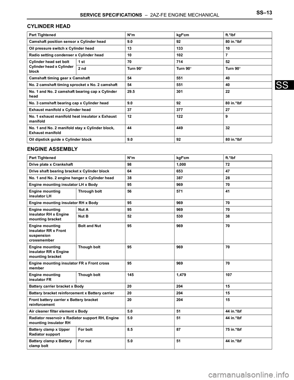
SERVICE SPECIFICATIONS – 2AZ-FE ENGINE MECHANICALSS–13
SS
CYLINDER HEAD
ENGINE ASSEMBLY
Part Tightened N*m kgf*cm ft.*lbf
Camshaft position sensor x Cylinder head 9.0 92 80 in.*lbf
Oil pressure switch x Cylinder head 13 133 10
Radio setting condenser x Cylinder head 10 102 7
Cylinder head set bolt
Cylinder head x Cylinder
block1 st 70 714 52
2 nd Turn 90
Tu r n 9 0Tu r n 9 0
Camshaft timing gear x Camshaft 54 551 40
No. 2 camshaft timing sprocket x No. 2 camshaft 54 551 40
No. 1 and No. 2 camshaft bearing cap x Cylinder
head29.5 301 22
No. 3 camshaft bearing cap x Cylinder head 9.0 92 80 in.*lbf
Exhaust manifold x Cylinder head 37 377 27
No. 1 exhaust manifold heat insulator x Exhaust
manifold12 122 9
No. 1 and No. 2 manifold stay x Cylinder block,
Exhaust manifold44 449 32
Oil dipstick guide x Cylinder block 9.0 92 80 in.*lbf
Part Tightened N*m kgf*cm ft.*lbf
Drive plate x Crankshaft 98 1,000 72
Drive shaft bearing bracket x Cylinder block 64 653 47
No. 1 and No. 2 engine hanger x Cylinder head 38 387 28
Engine mounting insulator LH x Body 95 969 70
Engine mounting
insulator LHThrough bolt 56 571 41
Engine mounting insulator RH x Body 95 969 70
Engine mounting
insulator RH x Engine
mounting bracketNut A 95 969 70
Nut B 52 530 38
Engine mounting
insulator RR x Front
suspension
crossmemberBolt and Nut 95 969 70
Engine mounting
insulator RR x Engine
mounting bracketThough bolt 95 969 70
Engine mounting insulator FR x Front cross
member95 969 70
Engine mounting
insulator FRThough bolt 145 1,479 107
Battery carrier bracket x Body 20 204 15
Battery bracket reinforcement x Battery carrier 20 204 15
Front battery carrier x Battery bracket
reinforcement20 204 15
Air cleaner filter element x Body 5.0 51 44 in.*lbf
Radiator reservoir x Radiator support RH, Engine
mounting insulator RH5.0 51 44 in.*lbf
Battery clamp x Upper
Radiator supportFor bolt 8.5 87 75 in.*lbf
Battery clamp x Battery
clamp boltFor nut 5.0 51 44 in.*lbf
Page 383 of 2000

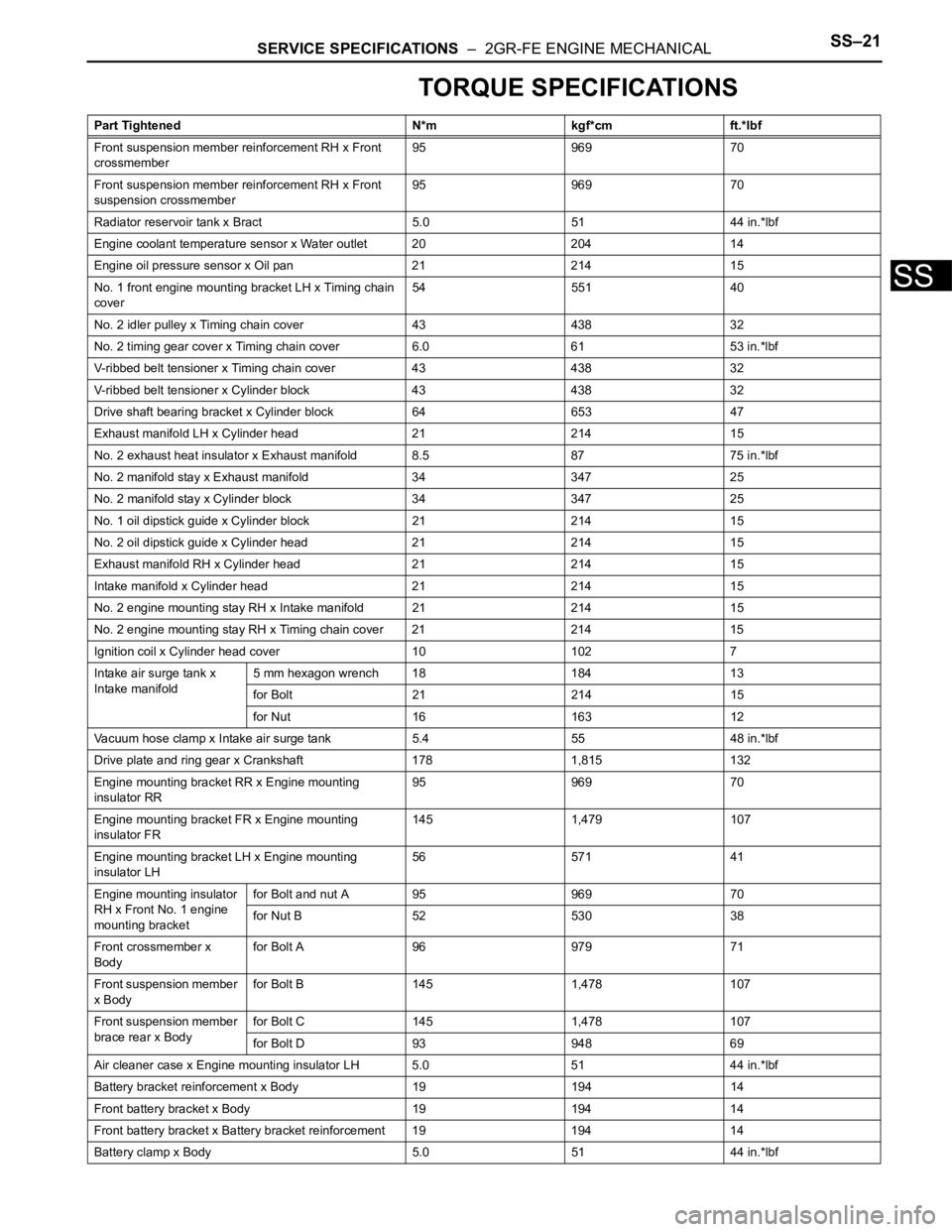
SERVICE SPECIFICATIONS – 2GR-FE ENGINE MECHANICALSS–21
SS
TORQUE SPECIFICATIONS
Part Tightened N*m kgf*cm ft.*lbf
Front suspension member reinforcement RH x Front
crossmember95 969 70
Front suspension member reinforcement RH x Front
suspension crossmember95 969 70
Radiator reservoir tank x Bract 5.0 51 44 in.*lbf
Engine coolant temperature sensor x Water outlet 20 204 14
Engine oil pressure sensor x Oil pan 21 214 15
No. 1 front engine mounting bracket LH x Timing chain
cover54 551 40
No. 2 idler pulley x Timing chain cover 43 438 32
No. 2 timing gear cover x Timing chain cover 6.0 61 53 in.*lbf
V-ribbed belt tensioner x Timing chain cover 43 438 32
V-ribbed belt tensioner x Cylinder block 43 438 32
Drive shaft bearing bracket x Cylinder block 64 653 47
Exhaust manifold LH x Cylinder head 21 214 15
No. 2 exhaust heat insulator x Exhaust manifold 8.5 87 75 in.*lbf
No. 2 manifold stay x Exhaust manifold 34 347 25
No. 2 manifold stay x Cylinder block 34 347 25
No. 1 oil dipstick guide x Cylinder block 21 214 15
No. 2 oil dipstick guide x Cylinder head 21 214 15
Exhaust manifold RH x Cylinder head 21 214 15
Intake manifold x Cylinder head 21 214 15
No. 2 engine mounting stay RH x Intake manifold 21 214 15
No. 2 engine mounting stay RH x Timing chain cover 21 214 15
Ignition coil x Cylinder head cover 10 102 7
Intake air surge tank x
Intake manifold5 mm hexagon wrench 18 184 13
for Bolt 21 214 15
for Nut 16 163 12
Vacuum hose clamp x Intake air surge tank 5.4 55 48 in.*lbf
Drive plate and ring gear x Crankshaft 178 1,815 132
Engine mounting bracket RR x Engine mounting
insulator RR95 969 70
Engine mounting bracket FR x Engine mounting
insulator FR145 1,479 107
Engine mounting bracket LH x Engine mounting
insulator LH56 571 41
Engine mounting insulator
RH x Front No. 1 engine
mounting bracketfor Bolt and nut A 95 969 70
for Nut B 52 530 38
Front crossmember x
Bodyfor Bolt A 96 979 71
Front suspension member
x Bodyfor Bolt B 145 1,478 107
Front suspension member
brace rear x Bodyfor Bolt C 145 1,478 107
for Bolt D 93 948 69
Air cleaner case x Engine mounting insulator LH 5.0 51 44 in.*lbf
Battery bracket reinforcement x Body 19 194 14
Front battery bracket x Body 19 194 14
Front battery bracket x Battery bracket reinforcement 19 194 14
Battery clamp x Body 5.0 51 44 in.*lbf
Page 429 of 2000
AIR CONDITIONING – AIR OUTLET CONTROL SERVO MOTOR (for Automatic Air Condi-
tioning System)AC–213
AC
INSTALLATION
1. INSTALL AIR OUTLET CONTROL SERVO MOTOR
(See page AC-196)
2. INSTALL AIR CONDITIONING UNIT
(a) Install the air conditioning radiator (see page AC-
197).
Page 510 of 2000

ET–4EXTERIOR – FRONT BUMPER
ET
REMOVAL
1. DISCONNECT CABLE FROM NEGATIVE BATTERY
TERMINAL
CAUTION:
Wait at least 90 seconds after disconnecting the
cable from the negative (-) battery terminal to
prevent airbag and seat belt pretensioner activation.
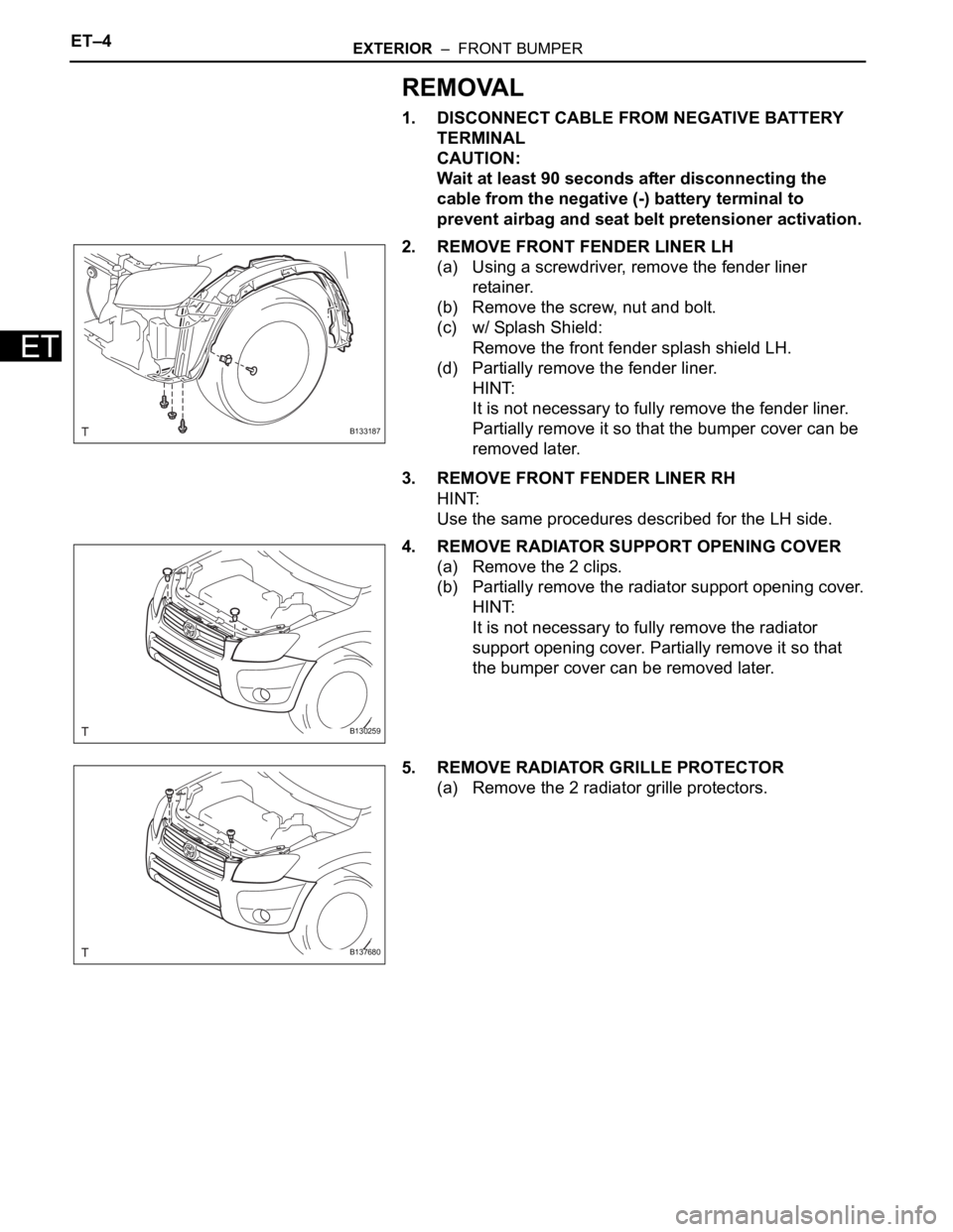
2. REMOVE FRONT FENDER LINER LH
(a) Using a screwdriver, remove the fender liner
retainer.
(b) Remove the screw, nut and bolt.
(c) w/ Splash Shield:
Remove the front fender splash shield LH.
(d) Partially remove the fender liner.
HINT:
It is not necessary to fully remove the fender liner.
Partially remove it so that the bumper cover can be
removed later.
3. REMOVE FRONT FENDER LINER RH
HINT:
Use the same procedures described for the LH side.
4. REMOVE RADIATOR SUPPORT OPENING COVER
(a) Remove the 2 clips.
(b) Partially remove the radiator support opening cover.
HINT:
It is not necessary to fully remove the radiator
support opening cover. Partially remove it so that
the bumper cover can be removed later.
5. REMOVE RADIATOR GRILLE PROTECTOR
(a) Remove the 2 radiator grille protectors.
B133187
B130259
B137680