Page 82 of 2000
ENGINE - 2GR-FE ENGINE
285EG24
Timing Chain Cover
Oil Pump
Housing
Oil Pump Rotors
(Cycloid Rotor)Crankshaft
To Cylinder
Block
From Oil
Filter
To
Oil FilterFrom
Oil Strainer
Oil passage in the oil pump
285EG25
Oil Jet Cross Section
Oil JetsCheck
Va l v eEngine Oil EG-86
2. Oil Pump
A compact cycloid rotor type oil pump directly driven by the crankshaft is used.
This oil pump has used an internal relief method which circulates relief oil to the suction passage in the
oil pump. This aims to minimize oil level change in the oil pan, reduce friction, and reduce air mixing rate
in the oil.
3. Oil Jet
Oil jets for cooling and lubricating the pistons have been provided in the cylinder block, in the center of
the right and left banks.
These oil jets contain a check valve to prevent oil from being fed when the oil pressure is low. This prevents
the overall oil pressure in the engine from dropping.
Page 182 of 2000

MAINTENANCE – UNDER HOODMA–7
MA
GENERAL MAINTENANCE
(2006/01- )
1. GENERAL NOTES
• Maintenance requirements vary depending on the
country.
• Check the maintenance schedule in the owner's
manual supplement.
• Following the maintenance schedule is mandatory.
• Determine the appropriate time to service the vehicle
using either miles driven or time elapsed, whichever
reaches the specification first.
• Maintain similar intervals between periodic
maintenance, unless otherwise noted.
• Failing to check each vehicle part could lead to poor
engine performance and increase exhaust emissions.
2. WINDSHIELD WASHER FLUID
(a) Check that there is sufficient fluid in the tank.
3. ENGINE COOLANT LEVEL
(a) Check that the coolant level is between the "FULL"
and "LOW" lines on the see-through reservoir.
4. RADIATOR AND HOSES
(a) Check that the front of the radiator is clean and not
blocked by leaves, dirt or bugs.
(b) Check the hoses for cracks, kinks, rot or loose
connections.
5. BATTERY ELECTROLYTE LEVEL
(a) Check that the electrolyte level of all the battery
cells is between the upper and lower level lines on
the case.
HINT:
If the electrolyte level is difficult to see, lightly shake
the vehicle.
6. BRAKE FLUID LEVEL
(a) Check that the brake fluid levels are near the upper
level lines on the see-through reservoirs.
7. ENGINE DRIVE BELT
(a) Check the drive belt for fraying, cracks, wear or
oiliness.
8. ENGINE OIL LEVEL
(a) Check the level on the dipstick with the engine
stopped.
9. AUTOMATIC TRANSAXLE FLUID LEVEL
10. EXHAUST SYSTEM
(a) Check for unusual exhaust sounds or abnormal
exhaust fumes. Inspect the cause and repair it.
Type See procedures
U151E See page AX-126
U151F See page AX-126
Page 382 of 2000
GF1A TRANSFER – TRANSFER SYSTEMTF–3
TF
PROBLEM SYMPTOMS TABLE
(2006/01- )
HINT:
Use the table below to help determine the cause of the
problem symptom. The potential causes of the symptoms are
listed in order of probability in the "Suspected area" column of
the table. Check each symptom by checking the suspected
areas in the order they are listed. Replace parts as
necessary.
Transfer system
Symptom Suspected Area See page
Noise1. Oil (level low)TF-45
2. Oil (wrong)TF-45
3. Transfer (faulty)TF-60
Oil leakage1. Oil (level too high)TF-45
2. Gasket (damaged)TF-55
3. Oil seal (worn or damaged)TF-55
4. O-ring (worn or damaged)TF-55
Page 419 of 2000

MA–12MAINTENANCE – CHASSIS
MA
GENERAL MAINTENANCE
(2006/01- )
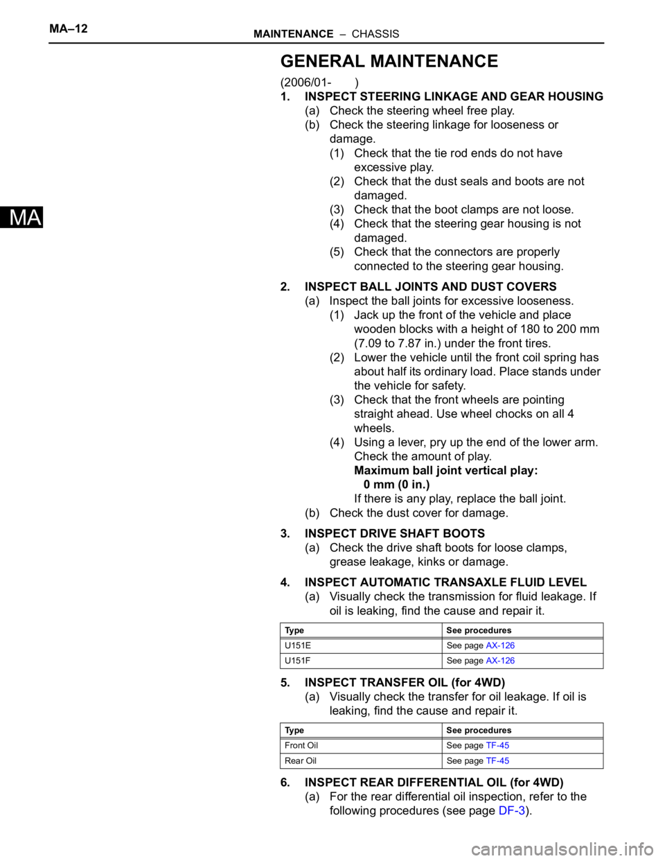
1. INSPECT STEERING LINKAGE AND GEAR HOUSING
(a) Check the steering wheel free play.
(b) Check the steering linkage for looseness or
damage.
(1) Check that the tie rod ends do not have
excessive play.
(2) Check that the dust seals and boots are not
damaged.
(3) Check that the boot clamps are not loose.
(4) Check that the steering gear housing is not
damaged.
(5) Check that the connectors are properly
connected to the steering gear housing.
2. INSPECT BALL JOINTS AND DUST COVERS
(a) Inspect the ball joints for excessive looseness.
(1) Jack up the front of the vehicle and place
wooden blocks with a height of 180 to 200 mm
(7.09 to 7.87 in.) under the front tires.
(2) Lower the vehicle until the front coil spring has
about half its ordinary load. Place stands under
the vehicle for safety.
(3) Check that the front wheels are pointing
straight ahead. Use wheel chocks on all 4
wheels.
(4) Using a lever, pry up the end of the lower arm.
Check the amount of play.
Maximum ball joint vertical play:
0 mm (0 in.)
If there is any play, replace the ball joint.
(b) Check the dust cover for damage.
3. INSPECT DRIVE SHAFT BOOTS
(a) Check the drive shaft boots for loose clamps,
grease leakage, kinks or damage.
4. INSPECT AUTOMATIC TRANSAXLE FLUID LEVEL
(a) Visually check the transmission for fluid leakage. If
oil is leaking, find the cause and repair it.
5. INSPECT TRANSFER OIL (for 4WD)
(a) Visually check the transfer for oil leakage. If oil is
leaking, find the cause and repair it.
6. INSPECT REAR DIFFERENTIAL OIL (for 4WD)
(a) For the rear differential oil inspection, refer to the
following procedures (see page DF-3).
Type See procedures
U151E See page AX-126
U151F See page AX-126
Type See procedures
Front Oil See page TF-45
Rear Oil See page TF-45
Page 976 of 2000

AX–144U140F AUTOMATIC TRANSAXLE – DIFFERENTIAL OIL SEAL
AX
REPLACEMENT
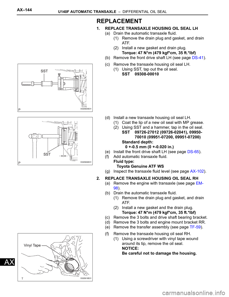
1. REPLACE TRANSAXLE HOUSING OIL SEAL LH
(a) Drain the automatic transaxle fluid.
(1) Remove the drain plug and gasket, and drain
AT F.
(2) Install a new gasket and drain plug.
Torque: 47 N*m (479 kgf*cm, 35 ft.*lbf)
(b) Remove the front drive shaft LH (see page DS-41).
(c) Remove the transaxle housing oil seal LH.
(1) Using SST, tap out the oil seal.
SST 09308-00010
(d) Install a new transaxle housing oil seal LH.
(1) Coat the lip of a new oil seal with MP grease.
(2) Using SST and a hammer, tap in the oil seal.
SST 09726-27012 (09726-02041), 09950-
70010 (09951-07200, 09951-07200)
Standard depth:
0 +-0.5 mm (0 +-0.020 in.)
(e) Install the front drive shaft LH (see page DS-65).
(f) Add automatic transaxle fluid.
Fluid type:
Toyota Genuine ATF WS
(g) Inspect the transaxle fluid level (see page AX-102).
2. REPLACE TRANSAXLE HOUSING OIL SEAL RH
(a) Remove the engine with transaxle (see page EM-
98).
(b) Drain the automatic transaxle fluid.
(1) Remove the drain plug and gasket, and drain
AT F.
(2) Install a new gasket and the drain plug.
Torque: 47 N*m (479 kgf*cm, 35 ft.*lbf)
(c) Remove the 3 bolts and drive shaft bearing bracket.
(d) Remove the 3 bolts and engine mount bracket RR.
(e) Remove the transfer assembly (see page TF-59).
(f) Remove the transaxle housing oil seal RH.
(1) Using a screwdriver with vinyl tape wound
around its tip, remove the oil seal.
NOTICE:
Be careful not to damage the housing.
D025835E01
D025836E01
D025618E01
Page 977 of 2000
U140F AUTOMATIC TRANSAXLE – DIFFERENTIAL OIL SEALAX–145
AX
(g) Install a new transaxle housing oil seal RH.
(1) Coat the lip of a new oil seal with MP grease.
(2) Using SST and a hammer, tap in the oil seal.
SST 09309-37010
Standard depth:
6.0 +-0.5 mm (0.236 +-0.020 in.)
(h) Install the transfer assembly (see page TF-75).
(i) Install the engine mount bracket RR with the 3 bolts.
Torque: 64 N*m (652 kgf*cm, 47 ft.*lbf)
(j) Install the drive shaft bearing bracket with the 3
bolts.
Torque: 64 N*m (653 kgf*cm, 47 ft.*lbf)
(k) Install the engine with transaxle (see page EM-105).
(l) Add automatic transaxle fluid.
Fluid type:
Toyota Genuine ATF WS
(m) Inspect the fluid level (see page AX-102).
D025837E01
Page 1162 of 2000

AX–170U151F AUTOMATIC TRANSAXLE – DIFFERENTIAL OIL SEAL
AX
REPLACEMENT
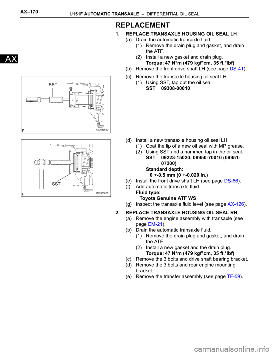
1. REPLACE TRANSAXLE HOUSING OIL SEAL LH
(a) Drain the automatic transaxle fluid.
(1) Remove the drain plug and gasket, and drain
the ATF.
(2) Install a new gasket and drain plug.
Torque: 47 N*m (479 kgf*cm, 35 ft.*lbf)
(b) Remove the front drive shaft LH (see page DS-41).
(c) Remove the transaxle housing oil seal LH.
(1) Using SST, tap out the oil seal.
SST 09308-00010
(d) Install a new transaxle housing oil seal LH.
(1) Coat the lip of a new oil seal with MP grease.
(2) Using SST and a hammer, tap in the oil seal.
SST 09223-15020, 09950-70010 (09951-
07200)
Standard depth:
0 +-0.5 mm (0 +-0.020 in.)
(e) Install the front drive shaft LH (see page DS-66).
(f) Add automatic transaxle fluid.
Fluid type:
Toyota Genuine ATF WS
(g) Inspect the transaxle fluid level (see page AX-126).
2. REPLACE TRANSAXLE HOUSING OIL SEAL RH
(a) Remove the engine assembly with transaxle (see
page EM-21).
(b) Drain the automatic transaxle fluid.
(1) Remove the drain plug and gasket, and drain
the ATF.
(2) Install a new gasket and the drain plug.
Torque: 47 N*m (479 kgf*cm, 35 ft.*lbf)
(c) Remove the 3 bolts and drive shaft bearing bracket.
(d) Remove the 3 bolts and rear engine mounting
bracket.
(e) Remove the transfer assembly (see page TF-59).
D025835E01
D025836E01
Page 1163 of 2000
U151F AUTOMATIC TRANSAXLE – DIFFERENTIAL OIL SEALAX–171
AX
(f) Remove the transaxle housing oil seal RH.
(1) Using a screwdriver with vinyl tape wound
around its tip, remove the oil seal.
NOTICE:
Be careful not to damage the housing.
(g) Install a new transaxle housing oil seal RH.
(1) Coat the lip of a new oil seal with MP grease.
(2) Using SST and a hammer, tap in the oil seal.
SST 09649-17010, 09950-70010 (09951-
07200)
Standard depth:
6.0 +-0.5 mm (0.236 +-0.020 in.)
(h) Install the transfer assembly (see page TF-75).
(i) Install the rear engine mounting bracket with the 3
bolts.
Torque: 64 N*m (652 kgf*cm, 47 ft.*lbf)
(j) Install the drive shaft bearing bracket with the 3
bolts.
Torque: 64 N*m (653 kgf*cm, 47 ft.*lbf)
(k) Install the engine with transaxle (see page EM-31).
(l) Add automatic transaxle fluid.
Fluid type:
Toyota Genuine ATF WS
(m) Inspect the fluid level (see page AX-126).
D030693E01
D030913E02