Page 24 of 2000

ENGINE - 2AZ-FE ENGINE
01NEG46Y
ArmatureSurface Commutator
Permanent Magnet
Brush
LengthEG-27
STARTING SYSTEM
1. General
A compact and lightweight PS (Planetary reduction-Segment conductor motor) type starter is used.
Because the PS type starter contains an armature that uses square-shaped conductors, and its surface
functions as a commutator, it has resulted in both improving its output torque and reducing its overall
length.
In place of the field coil used in the conventional type starter, the PS type starter uses two types of
permanent magnets: main magnets and interpolar magnets. The main magnets and interpolar magnets
have been efficiently arranged to increase the magnetic flux and to shorten the length of the yoke.
Specifications
Starter TypePS Type
Rating Output1.7 kW
Rating Voltage12 V
Length*1mm (in.)128 (5.04)
Weight g (lb)2950 (6.50)
Rotational Direction*2Counterclockwise
*1: Length from the mounted area to the rear end of the starter
*
2: Viewed from pinion side
Page 195 of 2000

2AZ-FE ENGINE MECHANICAL – DRIVE BELTEM–7
EM
REMOVAL
1. REMOVE RADIATOR SUPPORT OPENING COVER
2. REMOVE FRONT WHEEL RH
3. REMOVE FRONT FENDER APRON RH
4. REMOVE FRONT SUSPENSION MEMBER
REINFORCEMENT RH
(a) Remove the 4 bolts and reinforcement RH.
5. REMOVE FAN AND GENERATOR V BELT
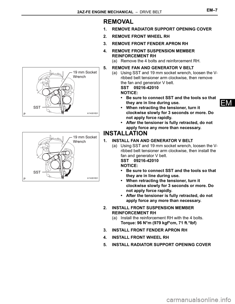
(a) Using SST and 19 mm socket wrench, loosen the V-
ribbed belt tensioner arm clockwise, then remove
the fan and generator V belt.
SST 09216-42010
NOTICE:
• Be sure to connect SST and the tools so that
they are in line during use.
• When retracting the tensioner, turn it
clockwise slowly for 3 seconds or more. Do
not apply force rapidly.
• After the tensioner is fully retracted, do not
apply force any more than necessary.
INSTALLATION
1. INSTALL FAN AND GENERATOR V BELT
(a) Using SST and 19 mm socket wrench, loosen the V-
ribbed belt tensioner arm clockwise, then install the
fan and generator V belt.
SST 09216-42010
NOTICE:
• Be sure to connect SST and the tools so that
they are in line during use.
• When retracting the tensioner, turn it
clockwise slowly for 3 seconds or more. Do
not apply force rapidly.
• After the tensioner is fully retracted, do not
apply force any more than necessary.
2. INSTALL FRONT SUSPENSION MEMBER
REINFORCEMENT RH
(a) Install the reinforcement RH with the 4 bolts.
Torque: 96 N*m (979 kgf*cm, 71 ft.*lbf)
3. INSTALL FRONT FENDER APRON RH
4. INSTALL FRONT WHEEL RH
5. INSTALL RADIATOR SUPPORT OPENING COVER
A114351E01
A114351E01
Page 436 of 2000

SEAT BELT – SEAT BELT WARNING SYSTEMSB–3
SB
SYSTEM DESCRIPTION
1. DRIVER SEAT BELT WARNING LIGHT
(a) When the driver seat belt is not fastened with the
ignition switch ON, the driver seat belt warning light
on the combination meter comes on to inform the
driver. The center airbag sensor detects the driver
seat belt status and sends signals to the
combination meter through the CAN bus line.
2. PASSENGER SEAT BELT WARNING LIGHT
(a) for Automatic air conditioning system:
When the passenger seat belt is not fastened with
the ignition switch ON and the passenger seat
occupied, check that the passenger seat belt
warning light on the heater control panel display
blinks. The combination meter detects the
passenger seat belt status and whether the
passenger seat is occupied.
(b) for Manual air conditioning system:
When the passenger seat belt is not fastened with
the ignition switch ON and the passenger seat
occupied, check that the passenger seat belt
warning light on the clock panel blinks. The
combination meter detects the passenger seat belt
status and whether the passenger seat is occupied.
Page 586 of 2000
2AZ-FE ENGINE MECHANICAL – TIMING CHAINEM–29
EM
33. REMOVE NO. 2 CHAIN SUB-ASSEMBLY
(a) Turn the crankshaft by 90
counterclockwise to align
the adjusting hole of the oil pump drive shaft
sprocket with the groove of the oil pump.
(b) Insert a 4 mm diameter bar into the adjusting hole of
the oil pump drive shaft sprocket to lock the gear in
position, and then remove the nut.
(c) Remove the bolt, chain tensioner plate and spring.
(d) Remove the oil pump drive sprocket, oil pump drive
shaft sprocket and No. 2 chain.
INSPECTION
1. INSPECT NO. 1 CHAIN TENSIONER
(a) Check that the plunger moves smoothly when the
ratchet pawl is raised with your finger.
(b) Release the ratchet pawl, then check that the
plunger is locked in place by the ratchet pawl and
does not move when pushed with your finger.
A098351E01
A098352E01
B011415E03
A098357E01
Page 596 of 2000
2AZ-FE ENGINE MECHANICAL – TIMING CHAINEM–39
EM
(b) Turn the crankshaft counterclockwise, then
disconnect the plunger knock pin from the hook.
(c) Turn the crankshaft clockwise, then check that the
plunger is extended.
13. INSTALL OIL PAN SUB-ASSEMBLY
(a) Remove any old packing material and be careful not
to drop any oil on the contact surfaces of the
cylinder block and oil pan.
(b) Apply a continuous bead of seal packing (Diameter
3.0 to 4.0 mm (0.118 to 0.157 in.)) as shown in the
illustration.
Seal packing:
Toyota Genuine Seal Packing Block, Three
Bond 1207B or Equivalent
NOTICE:
• Remove any oil from the contact surface.
• Instal l the oil pan wit hin 3 mi nut es of app lyi ng
seal packing.
• Do not add engine oil for at least 2 hours after
installing the oil pan.
(c) Install the oil pan to the cylinder block.
A112204E02
A112205E02
A114332E01
Page 606 of 2000

EM–622AZ-FE ENGINE MECHANICAL – CYLINDER HEAD
EM
(c) Apply air pressure of 100 kPa (1.0 kgf/cm2, 14 psi)
to the oil path, then turn the camshaft timing gear to
the advance direction (counterclockwise) by hand.
CAUTION:
Cover the paths with a shop rag to avoid oil
splashes.
HINT:
Depending on the air pressure, the camshaft timing
gear will turn to the advance angle side without
applying force by hand. Also, under the condition
that the pressure is difficult to apply because of air
leakage from the port, there may be the case that
the lock pin is difficult to release.
(d) Remove the flange bolt of the camshaft timing gear.
NOTICE:
• Be sure not to remove the other 4 bolts.
• When reusing the camshaft timing gear,
release the straight pin lock first, then install
the gear.
48. REMOVE CYLINDER HEAD SUB-ASSEMBLY
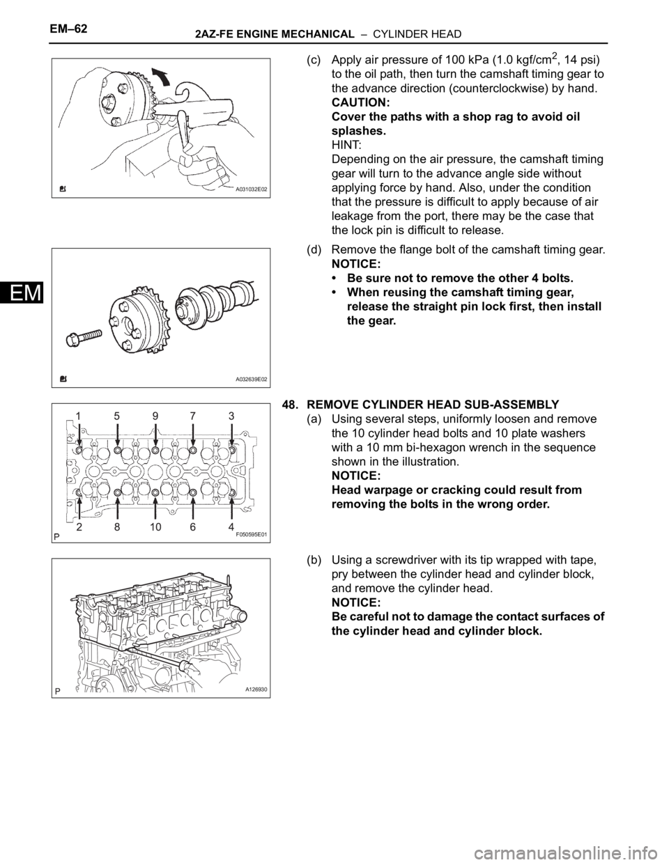
(a) Using several steps, uniformly loosen and remove
the 10 cylinder head bolts and 10 plate washers
with a 10 mm bi-hexagon wrench in the sequence
shown in the illustration.
NOTICE:
Head warpage or cracking could result from
removing the bolts in the wrong order.
(b) Using a screwdriver with its tip wrapped with tape,
pry between the cylinder head and cylinder block,
and remove the cylinder head.
NOTICE:
Be careful not to damage the contact surfaces of
the cylinder head and cylinder block.
A031032E02
A032639E02
F050595E01
A126930
Page 693 of 2000

EM–562GR-FE ENGINE MECHANICAL – ENGINE UNIT
EM
25. REMOVE NO. 1 CHAIN SUB-ASSEMBLY
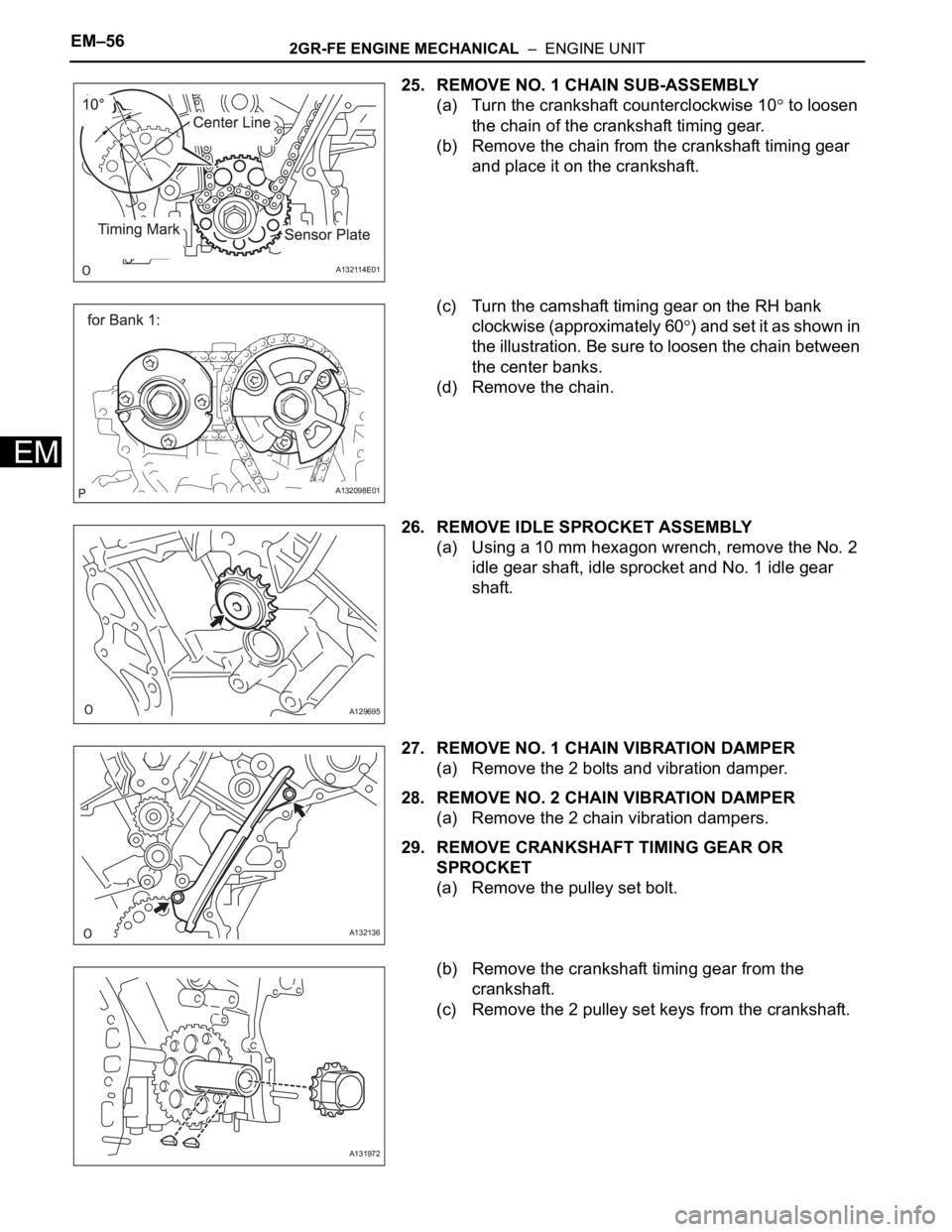
(a) Turn the crankshaft counterclockwise 10
to loosen
the chain of the crankshaft timing gear.
(b) Remove the chain from the crankshaft timing gear
and place it on the crankshaft.
(c) Turn the camshaft timing gear on the RH bank
clockwise (approximately 60
) and set it as shown in
the illustration. Be sure to loosen the chain between
the center banks.
(d) Remove the chain.
26. REMOVE IDLE SPROCKET ASSEMBLY
(a) Using a 10 mm hexagon wrench, remove the No. 2
idle gear shaft, idle sprocket and No. 1 idle gear
shaft.
27. REMOVE NO. 1 CHAIN VIBRATION DAMPER
(a) Remove the 2 bolts and vibration damper.
28. REMOVE NO. 2 CHAIN VIBRATION DAMPER
(a) Remove the 2 chain vibration dampers.
29. REMOVE CRANKSHAFT TIMING GEAR OR
SPROCKET
(a) Remove the pulley set bolt.
(b) Remove the crankshaft timing gear from the
crankshaft.
(c) Remove the 2 pulley set keys from the crankshaft.
A132114E01
A132098E01
A129695
A132136
A131972
Page 761 of 2000
EM–1242GR-FE ENGINE MECHANICAL – ENGINE UNIT
EM
(b) Turn the camshaft timing gear on the bank 1
counterclockwise to tighten the chain between the
banks.
NOTICE:
If reusing the idle sprocket, align one of the idle
sprocket's chain plate marks with one of the
chain's chain plates when installing the idle
sprocket.
(c) Align the mark plate and timing mark as shown in
the illustration and install the chain onto the
crankshaft timing gear.
HINT:
The chain mark plate is yellow.
(d) Temporarily tighten the pulley set bolt.
(e) Turn the crankshaft clockwise to set it to the bank 1
block bore center line (TDC / compression).
35. INSTALL CHAIN TENSIONER SLIPPER
(a) Install the chain tensioner slipper.
A122184E05
A132116E01
A132112E01