Page 602 of 2000
EM–582AZ-FE ENGINE MECHANICAL – CYLINDER HEAD
EM
19. REMOVE NO. 2 MANIFOLD STAY
(a) Remove the bolt, nut and stay.
20. REMOVE NO. 1 EXHAUST MANIFOLD HEAT
INSULATOR
(a) Remove the 4 bolts and heat insulator.
21. REMOVE EXHAUST MANIFOLD CONVERTER SUB-
ASSEMBLY
(a) Disconnect the air-fuel ratio sensor connector.
(b) Remove the 5 nuts, manifold converter and gasket.
22. DISCONNECT NO. 1 RADIATOR HOSE
(a) Disconnect the No. 1 radiator hose.
A112192
A112189
A098744E01
A112190
A114348
Page 630 of 2000

EM–862AZ-FE ENGINE MECHANICAL – CYLINDER HEAD
EM
22. INSTALL ENGINE MOUNTING INSULATOR RH (See
page EM-41)
23. INSTALL RADIATOR RESERVOIR (See page EM-112)
24. INSTALL GENERATOR ASSEMBLY (See page CH-15)
25. INSTALL FAN AND GENERATOR V BELT (See page
EM-7)
26. INSTALL FRONT SUSPENSION MEMBER
REINFORCEMENT RH (See page EM-7)
27. CONNECT ENGINE WIRE
(a) Connect the ground cable with the bolt.
Torque: 8.4 N*m (86 kgf*cm, 74 in.*lbf)
(b) Connect the camshaft position sensor connector.
(c) Connect the engine coolant temperature sensor
connector.
(d) Connect the engine oil pressure switch connector.
(e) Connect the radio setting condenser connector.
(f) Connect the heater water inlet hose.
28. CONNECT NO. 1 RADIATOR HOSE
(a) Connect the hose to the cylinder head.
29. INSTALL CAMSHAFT TIMING OIL CONTROL VALVE
ASSEMBLY (See page ES-396)
30. INSTALL EXHAUST MANIFOLD CONVERTER SUB-
ASSEMBLY
(a) Install a new gasket onto the cylinder head.
(b) Temporarily tighten the exhaust manifold converter
with the 5 nuts.
(c) Tighten the 5 nuts in the sequence shown in the
illustration.
Torque: 37 N*m (377 kgf*cm, 27 ft.*lbf)
(d) Connect the air-fuel ratio sensor connector.
A098748E01
A114348
A112190E01
A098744E01
Page 632 of 2000
EM–882AZ-FE ENGINE MECHANICAL – CYLINDER HEAD
EM
47. CHECK FOR ENGINE OIL LEAKS
48. CHECK FOR EXHAUST GAS LEAKS
49. INSPECT IGNITION TIMING (See page EM-1)
50. INSPECT ENGINE IDLING SPEED (See page EM-2)
51. INSPECT COMPRESSION (See page EM-3)
52. INSPECT CO/HC (See page EM-4)
53. INSTALL NO. 1 ENGINE COVER (See page EM-43)
54. INSTALL FRONT FENDER APRON RH
55. INSTALL NO. 1 ENGINE UNDER COVER
56. INSTALL FRONT WHEEL RH
57. INSTALL RADIATOR SUPPORT OPENING COVER
REPAIR
1. REPAIR VALVE SEATS
(a) If the seating is too high on the valve face, use 30
and 45
cutters to correct the seat.
(b) If the seating is too low on the valve face, use 75
and 45
cutters to correct the seat.
Standard width
(c) Lap the valve and valve seat by hand with an
abrasive compound.
(d) Recheck the valve seating position.
A128227E01
Item Standard Condition
Intake 1.0 to 1.4 mm (0.0394 to 0.0551 in.)
Exhaust 1.2 to 1.6 mm (0.0427 to 0.0630 in.)
Page 633 of 2000

EM–982AZ-FE ENGINE MECHANICAL – ENGINE ASSEMBLY
EM
REMOVAL
1. DISCHARGE FUEL SYSTEM PRESSURE (See page
FU-9)
2. DISCONNECT CABLE FROM NEGATIVE BATTERY
TERMINAL
CAUTION:
Wait at least 90 seconds after disconnecting the
cable from the negative (-) battery terminal to
prevent airbag and seat belt pretensioner activation.
3. REMOVE HOOD SUB-ASSEMBLY (See page ED-4)
4. REMOVE RADIATOR SUPPORT OPENING COVER
5. REMOVE BATTERY CLAMP SUB-ASSEMBLY
(a) Loosen the bolt and nut, and remove the battery
clamp.
6. REMOVE BATTERY
7. REMOVE BATTERY TRAY
8. REMOVE FRONT WHEEL
9. REMOVE NO. 1 ENGINE UNDER COVER
10. REMOVE NO. 2 ENGINE UNDER COVER
11. REMOVE FRONT FENDER APRON RH
12. REMOVE NO. 1 ENGINE COVER (See page EM-22)
13. DRAIN ENGINE COOLANT (See page CO-6)
14. DRAIN AUTOMATIC TRANSAXLE FLUID
(a) Drain automatic transaxle fluid for U241E (2WD)
(see page AX-146).
(b) Drain automatic transaxle fluid for U140F (4WD)
(see page AX-147).
15. REMOVE RADIATOR ASSEMBLY
(a) Remove the radiator (see page CO-29).
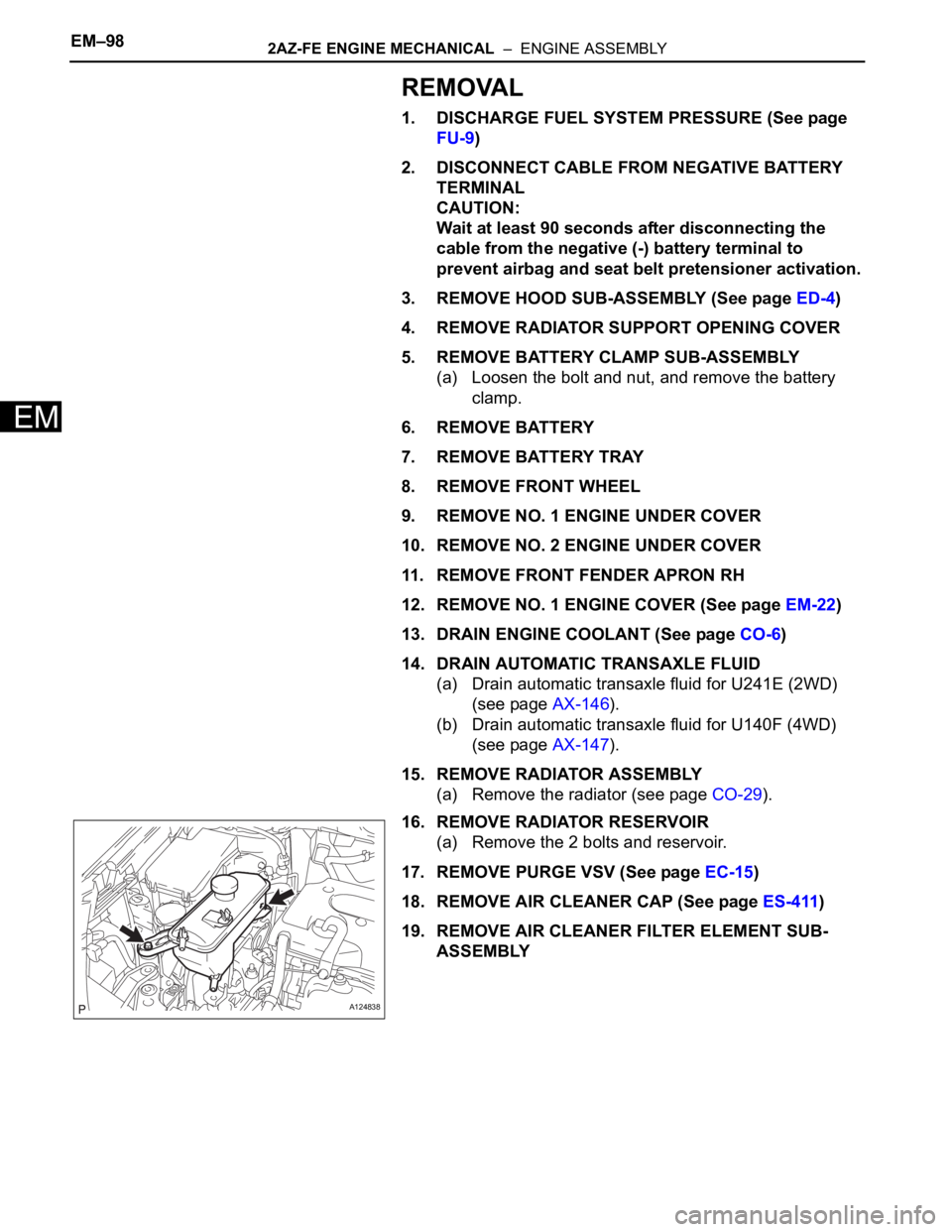
16. REMOVE RADIATOR RESERVOIR
(a) Remove the 2 bolts and reservoir.
17. REMOVE PURGE VSV (See page EC-15)
18. REMOVE AIR CLEANER CAP (See page ES-411)
19. REMOVE AIR CLEANER FILTER ELEMENT SUB-
ASSEMBLY
A124838
Page 648 of 2000

2AZ-FE ENGINE MECHANICAL – ENGINE ASSEMBLYEM–113
EM
(b) Install the air cleaner case with the 3 bolts.
Torque: 5.0 N*m (51 kgf*cm, 44 in.*lbf)
38. INSTALL AIR CLEANER FILTER ELEMENT SUB-
ASSEMBLY
39. INSTALL AIR CLEANER CAP (See page ES-413)
40. INSTALL PURGE VSV (See page EC-16)
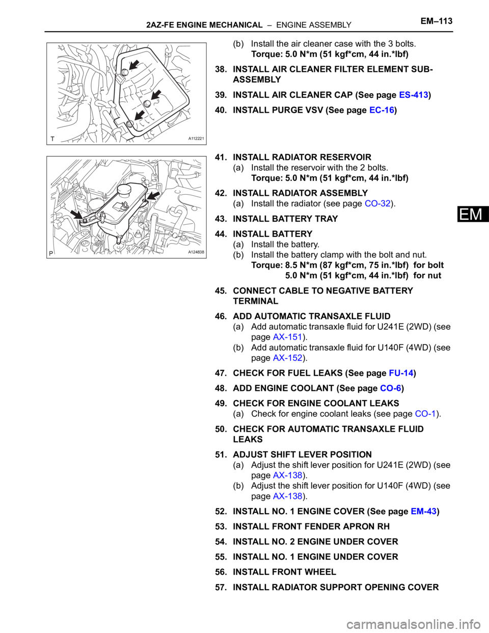
41. INSTALL RADIATOR RESERVOIR
(a) Install the reservoir with the 2 bolts.
Torque: 5.0 N*m (51 kgf*cm, 44 in.*lbf)
42. INSTALL RADIATOR ASSEMBLY
(a) Install the radiator (see page CO-32).
43. INSTALL BATTERY TRAY
44. INSTALL BATTERY
(a) Install the battery.
(b) Install the battery clamp with the bolt and nut.
Torque: 8.5 N*m (87 kgf*cm, 75 in.*lbf) for bolt
5.0 N*m (51 kgf*cm, 44 in.*lbf) for nut
45. CONNECT CABLE TO NEGATIVE BATTERY
TERMINAL
46. ADD AUTOMATIC TRANSAXLE FLUID
(a) Add automatic transaxle fluid for U241E (2WD) (see
page AX-151).
(b) Add automatic transaxle fluid for U140F (4WD) (see
page AX-152).
47. CHECK FOR FUEL LEAKS (See page FU-14)
48. ADD ENGINE COOLANT (See page CO-6)
49. CHECK FOR ENGINE COOLANT LEAKS
(a) Check for engine coolant leaks (see page CO-1).
50. CHECK FOR AUTOMATIC TRANSAXLE FLUID
LEAKS
51. ADJUST SHIFT LEVER POSITION
(a) Adjust the shift lever position for U241E (2WD) (see
page AX-138).
(b) Adjust the shift lever position for U140F (4WD) (see
page AX-138).
52. INSTALL NO. 1 ENGINE COVER (See page EM-43)
53. INSTALL FRONT FENDER APRON RH
54. INSTALL NO. 2 ENGINE UNDER COVER
55. INSTALL NO. 1 ENGINE UNDER COVER
56. INSTALL FRONT WHEEL
57. INSTALL RADIATOR SUPPORT OPENING COVER
A112221
A124838
Page 685 of 2000

2GR-FE ENGINE MECHANICAL – ENGINE ASSEMBLYEM–39
EM
(b) 4WD:
Connect the control cable (see page AX-154).
46. CONNECT RADIATOR HOSE INLET
47. CONNECT RADIATOR HOSE OUTLET
48. CONNECT OIL COOLER HOSE
49. CONNECT SUCTION HOSE SUB-ASSEMBLY (See
page AC-221)
50. INSTALL DISCHARGE HOSE SUB-ASSEMBLY (See
page AC-221)
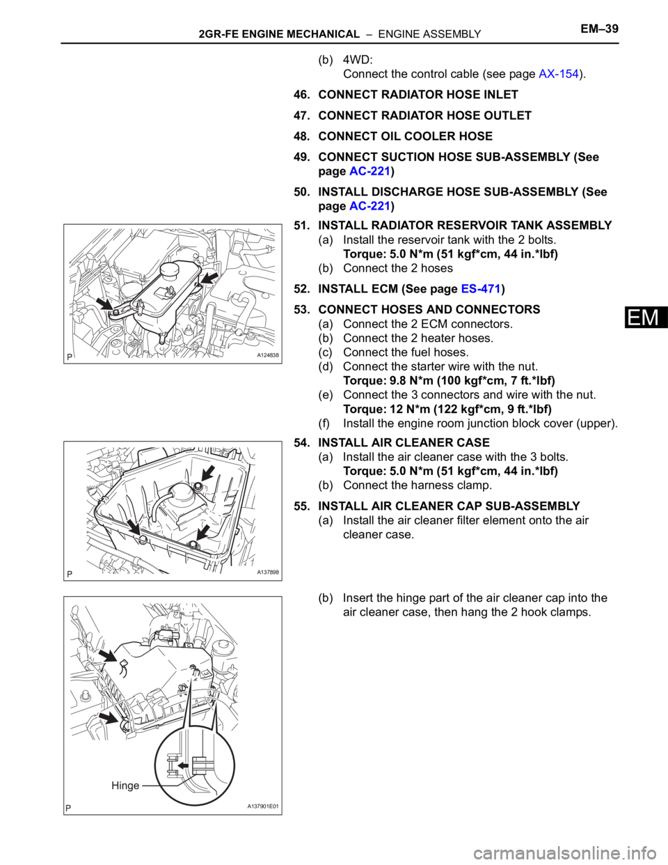
51. INSTALL RADIATOR RESERVOIR TANK ASSEMBLY
(a) Install the reservoir tank with the 2 bolts.
Torque: 5.0 N*m (51 kgf*cm, 44 in.*lbf)
(b) Connect the 2 hoses
52. INSTALL ECM (See page ES-471)
53. CONNECT HOSES AND CONNECTORS
(a) Connect the 2 ECM connectors.
(b) Connect the 2 heater hoses.
(c) Connect the fuel hoses.
(d) Connect the starter wire with the nut.
Torque: 9.8 N*m (100 kgf*cm, 7 ft.*lbf)
(e) Connect the 3 connectors and wire with the nut.
Torque: 12 N*m (122 kgf*cm, 9 ft.*lbf)
(f) Install the engine room junction block cover (upper).
54. INSTALL AIR CLEANER CASE
(a) Install the air cleaner case with the 3 bolts.
Torque: 5.0 N*m (51 kgf*cm, 44 in.*lbf)
(b) Connect the harness clamp.
55. INSTALL AIR CLEANER CAP SUB-ASSEMBLY
(a) Install the air cleaner filter element onto the air
cleaner case.
(b) Insert the hinge part of the air cleaner cap into the
air cleaner case, then hang the 2 hook clamps.
A124838
A137898
A137901E01
Page 688 of 2000
EM–422GR-FE ENGINE MECHANICAL – ENGINE ASSEMBLY
EM
79. INSTALL V-BANK COVER SUB-ASSEMBLY
(a) Attach the 3 clips to install the engine cover.
80. INSTALL RADIATOR SUPPORT OPENING COVER
(a) Install the cover with the 9 clips.
81. ADJUST FRONT WHEEL ALIGNMENT
(a) Adjust the front wheel alignment (see page SP-3).
82. INSPECT IDLE SPEED (See page EM-2)
A137900
A137899
Page 841 of 2000
2AZ-FE COOLING – WATER PUMPCO–11
CO
REMOVAL
1. DISCONNECT CABLE FROM NEGATIVE BATTERY
TERMINAL
CAUTION:
Wait at least 90 seconds after disconnecting the
cable from the negative (-) battery terminal to
prevent airbag and seat belt pretensioner activation.
2. REMOVE NO. 1 ENGINE UNDER COVER
3. REMOVE FRONT FENDER APRON RH
4. REMOVE RADIATOR SUPPORT OPENING COVER
5. DRAIN ENGINE COOLANT (See page CO-6)
6. REMOVE FRONT SUSPENSION MEMBER
REINFORCEMENT RH (See page EM-6)
7. REMOVE FAN AND GENERATOR V BELT (See page
EM-6)
8. REMOVE GENERATOR ASSEMBLY (See page CH-9)
9. REMOVE WATER PUMP PULLEY
(a) Using SST, remove the 4 bolts and water pump
pulley.
SST 09960-10010 (09962-01000, 09963-00700)
10. REMOVE WATER PUMP ASSEMBLY
(a) Remove the clamp of the crankshaft position sensor
from the water pump.
(b) Disconnect the wire of the crankshaft position
sensor from the clamp bracket.
(c) Remove the 4 bolts, 2 nuts and clamp bracket.
A098715E03
A094516E01
B012052E03