2006 TOYOTA RAV4 pcv valve
[x] Cancel search: pcv valvePage 484 of 2000

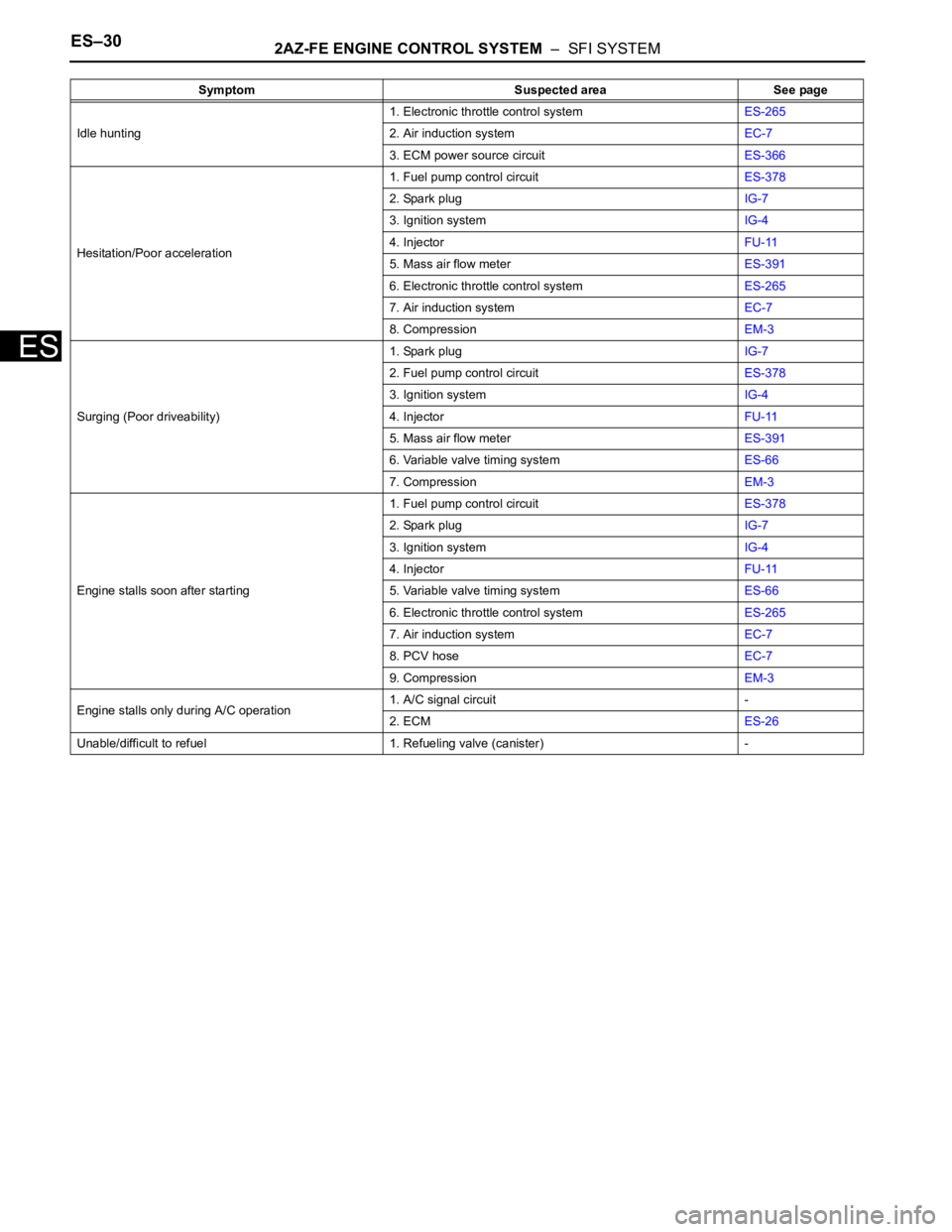
ES–302AZ-FE ENGINE CONTROL SYSTEM – SFI SYSTEM
ES
Idle hunting1. Electronic throttle control systemES-265
2. Air induction systemEC-7
3. ECM power source circuitES-366
Hesitation/Poor acceleration1. Fuel pump control circuitES-378
2. Spark plugIG-7
3. Ignition systemIG-4
4. InjectorFU-11
5. Mass air flow meterES-391
6. Electronic throttle control systemES-265
7. Air induction systemEC-7
8. CompressionEM-3
Surging (Poor driveability)1. Spark plugIG-7
2. Fuel pump control circuitES-378
3. Ignition systemIG-4
4. InjectorFU-11
5. Mass air flow meterES-391
6. Variable valve timing systemES-66
7. CompressionEM-3
Engine stalls soon after starting1. Fuel pump control circuitES-378
2. Spark plugIG-7
3. Ignition systemIG-4
4. InjectorFU-11
5. Variable valve timing systemES-66
6. Electronic throttle control systemES-265
7. Air induction systemEC-7
8. PCV hoseEC-7
9. CompressionEM-3
Engine stalls only during A/C operation1. A/C signal circuit -
2. ECMES-26
Unable/difficult to refuel 1. Refueling valve (canister) - Symptom Suspected area See page
Page 557 of 2000

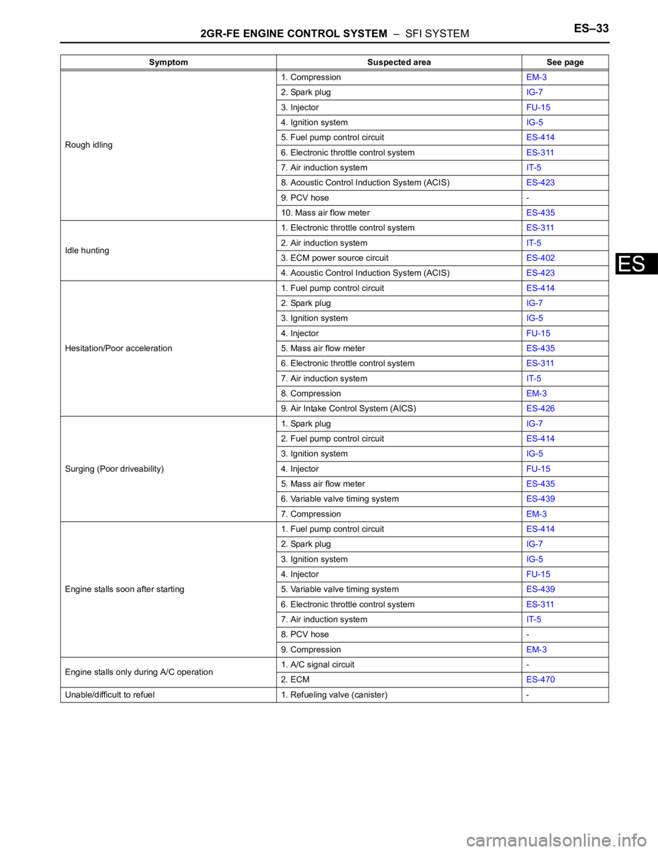
2GR-FE ENGINE CONTROL SYSTEM – SFI SYSTEMES–33
ES
Rough idling1. CompressionEM-3
2. Spark plugIG-7
3. InjectorFU-15
4. Ignition systemIG-5
5. Fuel pump control circuitES-414
6. Electronic throttle control systemES-311
7. Air induction systemIT-5
8. Acoustic Control Induction System (ACIS)ES-423
9. PCV hose -
10. Mass air flow meterES-435
Idle hunting1. Electronic throttle control systemES-311
2. Air induction systemIT-5
3. ECM power source circuitES-402
4. Acoustic Control Induction System (ACIS)ES-423
Hesitation/Poor acceleration1. Fuel pump control circuitES-414
2. Spark plugIG-7
3. Ignition systemIG-5
4. InjectorFU-15
5. Mass air flow meterES-435
6. Electronic throttle control systemES-311
7. Air induction systemIT-5
8. CompressionEM-3
9. Air Intake Control System (AICS)ES-426
Surging (Poor driveability)1. Spark plugIG-7
2. Fuel pump control circuitES-414
3. Ignition systemIG-5
4. InjectorFU-15
5. Mass air flow meterES-435
6. Variable valve timing systemES-439
7. CompressionEM-3
Engine stalls soon after starting1. Fuel pump control circuitES-414
2. Spark plugIG-7
3. Ignition systemIG-5
4. InjectorFU-15
5. Variable valve timing systemES-439
6. Electronic throttle control systemES-311
7. Air induction systemIT-5
8. PCV hose -
9. CompressionEM-3
Engine stalls only during A/C operation1. A/C signal circuit -
2. ECMES-470
Unable/difficult to refuel 1. Refueling valve (canister) -Symptom Suspected area See page
Page 1949 of 2000

2AZ-FE ENGINE CONTROL SYSTEM – SFI SYSTEMES–61
ES
P0171 System Too Lean
(Bank 1)- Air induction system
- Injector blockage
- MAF meter
- ECT sensor
- Fuel pressure
- Gas leakage from
exhaust system
- Open or short in A/F
sensor (sensor 1)
circuit
- A/F sensor (sensor
1)
- A/F sensor heater
(sensor 1)
- Integration relay
(EFI MAIN relay)
- A/F sensor heater
and EFI MAIN relay
circuits
- PCV hose
connections
- PCV valve and hose
- ECMComes on DTC storedES-147
P0172 System Too Rich
(Bank 1)- Injector leakage or
blockage
- MAF meter
- ECT sensor
- Ignition system
- Fuel pressure
- Gas leakage from
exhaust system
- Open or short in A/F
sensor (sensor 1)
circuit
- A/F sensor (sensor
1)
- A/F sensor heater
(sensor 1)
- Integration relay
(EFI MAIN relay)
- A/F sensor heater
and EFI MAIN relay
circuits
- ECMComes on DTC storedES-147
P0220 Throttle / Pedal
Position Sensor /
Switch "B" Circuit- TP sensor (built into
throttle body)
- ECMComes on DTC storedES-114
P0222 Throttle / Pedal
Position Sensor /
Switch "B" Circuit
Low Input- TP sensor (built into
throttle body)
- Short in VTA2 circuit
- Open in VC circuit
- ECMComes on DTC storedES-114
P0223 Throttle / Pedal
Position Sensor /
Switch "B" Circuit
High Input- TP sensor (built into
throttle body)
- Open in VTA2 circuit
- Open in E2 circuit
- Short between VC
and VTA2 circuits
- ECMComes on DTC storedES-114 DTC No. Detection Item Trouble Areas MIL Memory See page
Page 1950 of 2000

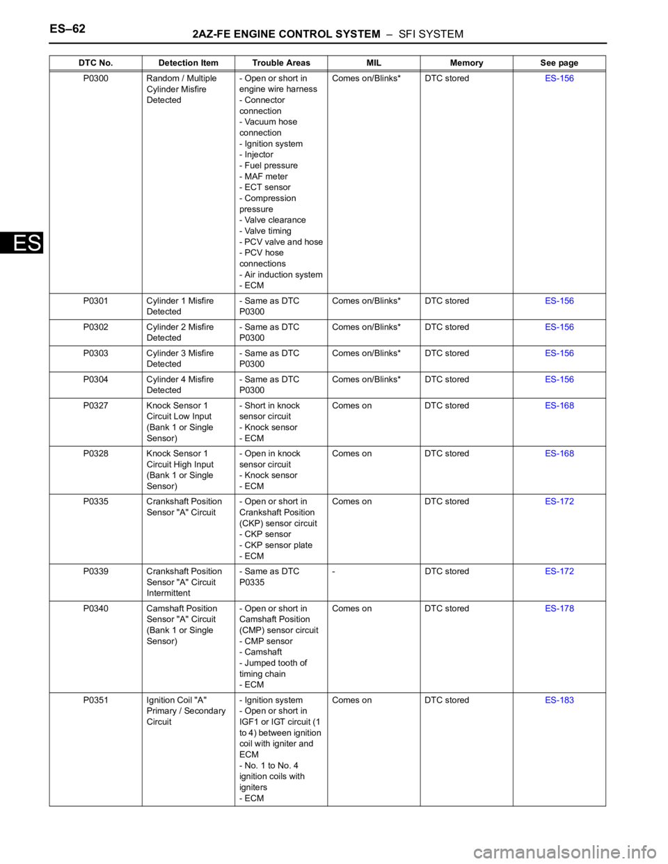
ES–622AZ-FE ENGINE CONTROL SYSTEM – SFI SYSTEM
ES
P0300 Random / Multiple
Cylinder Misfire
Detected- Open or short in
engine wire harness
- Connector
connection
- Vacuum hose
connection
- Ignition system
- Injector
- Fuel pressure
- MAF meter
- ECT sensor
- Compression
pressure
- Valve clearance
- Valve timing
- PCV valve and hose
- PCV hose
connections
- Air induction system
- ECMComes on/Blinks* DTC storedES-156
P0301 Cylinder 1 Misfire
Detected- Same as DTC
P0300Comes on/Blinks* DTC storedES-156
P0302 Cylinder 2 Misfire
Detected- Same as DTC
P0300Comes on/Blinks* DTC storedES-156
P0303 Cylinder 3 Misfire
Detected- Same as DTC
P0300Comes on/Blinks* DTC storedES-156
P0304 Cylinder 4 Misfire
Detected- Same as DTC
P0300Comes on/Blinks* DTC storedES-156
P0327 Knock Sensor 1
Circuit Low Input
(Bank 1 or Single
Sensor)- Short in knock
sensor circuit
- Knock sensor
- ECMComes on DTC storedES-168
P0328 Knock Sensor 1
Circuit High Input
(Bank 1 or Single
Sensor)- Open in knock
sensor circuit
- Knock sensor
- ECMComes on DTC storedES-168
P0335 Crankshaft Position
Sensor "A" Circuit- Open or short in
Crankshaft Position
(CKP) sensor circuit
- CKP sensor
- CKP sensor plate
- ECMComes on DTC storedES-172
P0339 Crankshaft Position
Sensor "A" Circuit
Intermittent- Same as DTC
P0335- DTC storedES-172
P0340 Camshaft Position
Sensor "A" Circuit
(Bank 1 or Single
Sensor)- Open or short in
Camshaft Position
(CMP) sensor circuit
- CMP sensor
- Camshaft
- Jumped tooth of
timing chain
- ECMComes on DTC storedES-178
P0351 Ignition Coil "A"
Primary / Secondary
Circuit- Ignition system
- Open or short in
IGF1 or IGT circuit (1
to 4) between ignition
coil with igniter and
ECM
- No. 1 to No. 4
ignition coils with
igniters
- ECMComes on DTC storedES-183 DTC No. Detection Item Trouble Areas MIL Memory See page
Page 1988 of 2000

ES–1002AZ-FE ENGINE CONTROL SYSTEM – SFI SYSTEM
ES
DESCRIPTION
Refer to DTC P0100 (see page ES-86).
MONITOR DESCRIPTION
The MAF meter is a sensor that measures the amount of air flowing through the throttle valve. The ECM
uses this information to determine the fuel injection time and to provide an appropriate air-fuel ratio. Inside
the MAF meter, there is a heated platinum wire which is exposed to the flow of intake air. By applying a
specific electrical current to the wire, the ECM heats it to a specific temperature. The flow of incoming air
cools both the wire and an internal thermistor, affecting their resistance. To maintain a constant current
value, the ECM varies the voltage applied to these components of the MAF meter. The voltage level is
proportional to the airflow through the sensor, and the ECM uses it to calculate the intake air volume.
The ECM monitors the average engine load value ratio to check the MAF meter for malfunctions. The
average engine load value ratio is obtained by comparing the average engine load calculated from the
MAF meter output to the average engine load estimated from the driving conditions, such as the engine
speed and the throttle opening angle. If the average engine load value ratio is below the threshold value,
the ECM determines that the intake air volume is low, and if the average engine load value ratio is above
the threshold value, the ECM determines that the intake air volume is high.
If this is detected in 2 consecutive driving cycles, the MIL is illuminated and a DTC is set.
MONITOR STRATEGY
TYPICAL ENABLING CONDITIONS
DTC P0101Mass Air Flow Circuit Range / Performance
Problem
DTC No. DTC Detection Conditions Trouble Areas
P0101Conditions (a), (b), (c), (d) and (e) continue for more than 10
seconds (2 trip detection logic):
(a) Engine running
(b) Engine coolant temperature 70
C (158F) or higher
(c) Throttle Position (TP) sensor voltage 0.24 V or more
(d) Average engine load value ratio less than 0.85, or more
than 1.15 (varies with estimated engine load)
Average engine load value ratio = Average engine load based
on MAF meter output / Average engine load estimated from
driving conditions
(e) Average air-fuel ratio less than -20 %, or more than 20 %• Mass Air Flow (MAF) meter
• Air induction system
• PCV hose connections
Related DTCs P0101: Mass air flow meter rationality
Required Sensors/Components (Main) Mass air flow meter
Required Sensors/Components (Related)Crankshaft Position (CKP) sensor, Engine Coolant Temperature
(ECT) sensor and Throttle Position (TP) sensor
Frequency of Operation Continuous
Duration 10 seconds
MIL Operation 2 driving cycles
Sequence of Operation None
Monitor runs whenever following DTCs not presentP0115 - P0118 (ECT sensor)
P0120 - P0223, P2135 (TP sensor)
P0125 (Insufficient ECT for closed loop)
P0335 (CKP sensor)
P0340 (CMP sensor)
Throttle position (TP sensor voltage) 0.24 V or more
Engine Running
Battery voltage 10.5 V or more