2006 TOYOTA RAV4 coolant level
[x] Cancel search: coolant levelPage 27 of 2000

ENGINE - 2AZ-FE ENGINE EG-30
ENGINE CONTROL SYSTEM
1. General
The engine control system for the 2AZ-FE engine has the following systems.
System
Outline
SFI
Sequential Multiport
Fuel InjectionAn L-type SFI system directly detects the intake air volume with a hot-wire
type mass air flow meter.
The fuel injection system is a sequential multiport fuel injection system.
ESA
Electronic Spark
AdvanceIgnition timing is determined by the ECM based on signals from various sensors.
The ECM corrects ignition timing in response to engine knocking.
ETCS-i
Electronic
Optimally controls the throttle valve opening in accordance with the amount of
accelerator pedal effort and the condition of the engine and the vehicle.
Electronic
Throttle Control
System-intelligent
(See page-43)A linkless-type is used, without an accelerator cable.
An accelerator pedal position sensor is provided on the accelerator pedal.
A non-contact type throttle position sensor and accelerator pedal position
sensor are used.
VVT-i
Va r i a b l e Va l v e
Timing-intelligent
(See page EG-48)
Controls the intake camshaft to an optimal valve timing in accordance with the
engine condition.
Air-fuel Ratio
Sensor, Oxygen
Sensor Heater
ControlMaintains the temperature of the air-fuel ratio sensor or oxygen sensor at an
appropriate level to realize accuracy of detection of the oxygen concentration in
the exhaust gas.
Air Conditioning
Cut-off ControlBy turning the air conditioning compressor ON or OFF in accordance with the
engine condition, drivability is maintained.
Cooling Fan Control
(See page EG-52)Radiator cooling fan operation is controlled by signals from ECM based on the
engine coolant temperature sensor signal and the condition of the air
conditioning operation.
Fuel Pump Control
(See page EG-53)Fuel pump operation is controlled by signal from the ECM.
The fuel pump is stopped when the SRS driver’s and front passenger’s airbags
are deployed.
Evapotative Emission
The ECM controls the purge flow of evaporative emissions (HC) in the canister
in accordance with engine conditions.
Evapotative Emission
Control
(See page EG-54)Approximately five hours after the ignition switch has been turned OFF, the
ECM operates the canister pump module to detect any evaporative emission
leakage occurring in the EVAP (evaporative emission) control system through
changes in the 0.02 in. leak pressure.
Charging Control
(See page EG-65)The ECM regulates the charging voltage of the generator in accordance with the
driving conditions and the charging state of the battery.
(Continued)
Page 182 of 2000

MAINTENANCE – UNDER HOODMA–7
MA
GENERAL MAINTENANCE
(2006/01- )
1. GENERAL NOTES
• Maintenance requirements vary depending on the
country.
• Check the maintenance schedule in the owner's
manual supplement.
• Following the maintenance schedule is mandatory.
• Determine the appropriate time to service the vehicle
using either miles driven or time elapsed, whichever
reaches the specification first.
• Maintain similar intervals between periodic
maintenance, unless otherwise noted.
• Failing to check each vehicle part could lead to poor
engine performance and increase exhaust emissions.
2. WINDSHIELD WASHER FLUID
(a) Check that there is sufficient fluid in the tank.
3. ENGINE COOLANT LEVEL
(a) Check that the coolant level is between the "FULL"
and "LOW" lines on the see-through reservoir.
4. RADIATOR AND HOSES
(a) Check that the front of the radiator is clean and not
blocked by leaves, dirt or bugs.
(b) Check the hoses for cracks, kinks, rot or loose
connections.
5. BATTERY ELECTROLYTE LEVEL
(a) Check that the electrolyte level of all the battery
cells is between the upper and lower level lines on
the case.
HINT:
If the electrolyte level is difficult to see, lightly shake
the vehicle.
6. BRAKE FLUID LEVEL
(a) Check that the brake fluid levels are near the upper
level lines on the see-through reservoirs.
7. ENGINE DRIVE BELT
(a) Check the drive belt for fraying, cracks, wear or
oiliness.
8. ENGINE OIL LEVEL
(a) Check the level on the dipstick with the engine
stopped.
9. AUTOMATIC TRANSAXLE FLUID LEVEL
10. EXHAUST SYSTEM
(a) Check for unusual exhaust sounds or abnormal
exhaust fumes. Inspect the cause and repair it.
Type See procedures
U151E See page AX-126
U151F See page AX-126
Page 220 of 2000

IN–48INTRODUCTION – TERMS
IN
GLOSSARY OF SAE AND TOYOTA
TERMS
This glossary lists all SAE-J1930 terms and abbreviations
used in this manual in compliance with SAE
recommendations, as well as their TOYOTA equivalents.
SAE
ABBREVIATIONSSAE TERMS TOYOTA TERMS ( )-ABBREVIATIONS
3GR Third Gear -
4GR Fourth Gear -
A/C Air Conditioning Air Conditioner
ACL Air Cleaner Air Cleaner, A/CL
AIR Secondary Air Injection Air Injection (AI)
AP Accelerator Pedal -
B+ Battery Positive Voltage +B, Battery Voltage
BARO Barometric Pressure HAC
CAC Charge Air Cooler Intercooler
CARB Carburetor Carburetor
CFI Continuous Fuel Injection -
CKP Crankshaft Position Crank Angle
CL Closed Loop Closed Loop
CMP Camshaft Position Cam Angle
CPP Clutch Pedal Position -
CTOX Continuous Trap Oxidizer -
CTP Closed Throttle Position LL ON, Idle ON
DFI Direct Fuel Injection Direct Injection (DI/INJ)
DI Distributor Ignition -
DLC3 Data Link Connector 3 OBD II Diagnostic Connector
DTC Diagnostic Trouble Code Diagnostic Trouble Code
DTM Diagnostic Test Mode -
ECL Engine Coolant Level -
ECM Engine Control Module Engine Electronic Control Unit (ECU)
ECT Engine Coolant Temperature Coolant Temperature, Water Temperature (THW)
EEPROM Electrically Erasable Programmable Read Only MemoryElectrically Erasable Programmable Read Only Memory
(EEPROM)
EFE Early Fuel Evaporation Cold Mixture Heater (CMH), Heat Control Valve (HCV)
EGR Exhaust Gas Recirculation Exhaust Gas Recirculation (EGR)
EI Electronic Ignition Distributorless Ignition (DLI)
EM Engine Modification Engine Modification (EM)
EPROM Erasable Programmable Read Only Memory Programmable Read Only Memory (PROM)
EVAP Evaporative Emission Evaporative Emission Control (EVAP)
FC Fan Control -
FEEPROMFlash Electrically Erasable Programmable Read Only
Memory-
FEPROM Flash Erasable Programmable Read Only Memory -
FF Flexible Fuel -
FP Fuel Pump Fuel Pump
GEN Generator Alternator
GND Ground Ground (GND)
HO2S Heated Oxygen Sensor Heated Oxygen Sensor (HO2S)
IAC Idle Air Control Idle Speed Control (ISC)
Page 496 of 2000

ES–422AZ-FE ENGINE CONTROL SYSTEM – SFI SYSTEM
ES
FREEZE FRAME DATA
1. DESCRIPTION
Freeze frame data records the engine conditions (fuel
system, calculated load, engine coolant temperature,
fuel trim, engine speed, vehicle speed, etc.) when a
malfunction is detected. When troubleshooting, it can
help determine if the vehicle was running or stopped, the
engine was warmed up or not, the air-fuel ratio was Lean
or Rich, and other data from the time the malfunction
occurred.
HINT:
If it is impossible to duplicate the problem even though a
DTC is detected, confirm the freeze frame data.
The ECM records engine conditions in the form of freeze
frame data every 0.5 seconds. Using the intelligent
tester, 5 separate sets of freeze frame data can be
checked.
– 3 data sets before the DTC was set.
– 1 data set when the DTC was set.
– 1 data set after the DTC was set.
These data sets can be used to simulate the condition
of the vehicle around the time of the occurrence of the
malfunction. The data may assist in identifying the
cause of the malfunction, and in judging whether it
was temporary or not.
2. LIST OF FREEZE FRAME DATA
A103809E11
LABEL
(Intelligent Tester Display)Measurement Item Diagnostic Note
INJECTOR Injection period of No. 1 cylinder -
IGN ADVANCE Ignition advance -
CALC LOAD Calculated load Calculated load by ECM
VEHICLE LOAD Vehicle load -
MAF Mass air flow volumeIf approximately 0.0 g/sec.:
• Mass air flow meter power source circuit
open or short
• VG circuit open or short
If 160.0 g/sec. or more:
• E2G circuit open
ENGINE SPD Engine speed -
VEHICLE SPD Vehicle speed Speed indicated on speedometer
COOLANT TEMP Engine coolant temperatureIf -40
C (-40F), sensor circuit open
If 140
C (284F) or more, sensor circuit
shorted
INTAKE AIR Intake air temperature If -40
C (-40F), sensor circuit open
If 140
C (284F) or more, sensor circuit
shorted
AIR-FUEL RATIO Ratio compared to stoichiometric level -
PURGE DENSITY Learning value of purge density -
EVAP PURGE FLOWRatio of evaporative purge flow to intake air
volume-
EVAP PURGE VSV EVAP purge VSV duty ratio -
KNOCK CRRT VAL Correction learning value of knocking -
Page 567 of 2000
2GR-FE ENGINE CONTROL SYSTEM – SFI SYSTEMES–43
ES
3. 2 TRIP DETECTION LOGIC
When a malfunction is first detected, the malfunction is
temporarily stored in the ECM memory (1st trip). If the
same malfunction is detected during the next
subsequent drive cycle, the MIL is illuminated (2nd trip).
4. FREEZE FRAME DATA
Freeze frame data records the engine conditions (fuel
system, calculated engine load, engine coolant
temperature, fuel trim, engine speed, vehicle speed,
etc.) when malfunctions are detected. When
troubleshooting, freeze frame data can help determine if
the vehicle was moving or stationary, if the engine was
warmed up or not, if the air-fuel ratio was lean or rich,
and other data from the time the malfunction occurred.
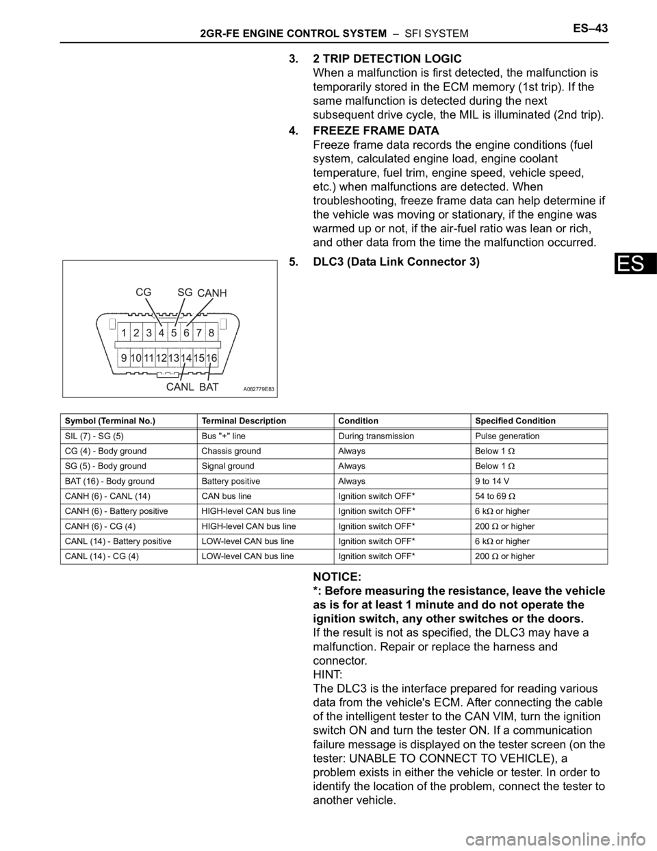
5. DLC3 (Data Link Connector 3)
NOTICE:
*: Before measuring the resistance, leave the vehicle
as is for at least 1 minute and do not operate the
ignition switch, any other switches or the doors.
If the result is not as specified, the DLC3 may have a
malfunction. Repair or replace the harness and
connector.
HINT:
The DLC3 is the interface prepared for reading various
data from the vehicle's ECM. After connecting the cable
of the intelligent tester to the CAN VIM, turn the ignition
switch ON and turn the tester ON. If a communication
failure message is displayed on the tester screen (on the
tester: UNABLE TO CONNECT TO VEHICLE), a
problem exists in either the vehicle or tester. In order to
identify the location of the problem, connect the tester to
another vehicle.
A082779E83
Symbol (Terminal No.) Terminal Description Condition Specified Condition
SIL (7) - SG (5) Bus "+" line During transmission Pulse generation
CG (4) - Body ground Chassis ground Always Below 1
SG (5) - Body ground Signal ground Always Below 1
BAT (16) - Body ground Battery positive Always 9 to 14 V
CANH (6) - CANL (14) CAN bus line Ignition switch OFF* 54 to 69
CANH (6) - Battery positive HIGH-level CAN bus line Ignition switch OFF* 6 k or higher
CANH (6) - CG (4) HIGH-level CAN bus line Ignition switch OFF* 200
or higher
CANL (14) - Battery positive LOW-level CAN bus line Ignition switch OFF* 6 k
or higher
CANL (14) - CG (4) LOW-level CAN bus line Ignition switch OFF* 200
or higher
Page 570 of 2000

ES–462GR-FE ENGINE CONTROL SYSTEM – SFI SYSTEM
ES
FREEZE FRAME DATA
1. DESCRIPTION
Freeze frame data records the engine conditions (fuel
system, calculated load, engine coolant temperature,
fuel trim, engine speed, vehicle speed, etc.) when a
malfunction is detected. When troubleshooting, it can
help determine if the vehicle was running or stopped, the
engine was warmed up or not, the air-fuel ratio was Lean
or Rich, and other data from the time the malfunction
occurred.
HINT:
If it is impossible to duplicate the problem even though a
DTC is detected, confirm the freeze frame data.
The ECM records engine conditions in the form of freeze
frame data every 0.5 seconds. Using the intelligent
tester, 5 separate sets of freeze frame data can be
checked.
– 3 data sets before the DTC was set.
– 1 data set when the DTC was set.
– 1 data set after the DTC was set.
These data sets can be used to simulate the condition
of the vehicle around the time of the occurrence of the
malfunction. The data may assist in identifying the
cause of the malfunction, and in judging whether it
was temporary or not.
2. LIST OF FREEZE FRAME DATA
A103809E11
LABEL
(Intelligent Tester Display)Measurement Item Diagnostic Note
INJECTOR Injection period of No. 1 cylinder -
IGN ADVANCE Ignition advance -
CALC LOAD Calculated load Calculated load by ECM
VEHICLE LOAD Vehicle load -
MAF Mass air flow volumeIf approximately 0.0 g/sec.:
• Mass air flow meter power source circuit
open or short
• VG circuit open or short
If 160.0 g/sec. or more:
• E2G circuit open
ENGINE SPD Engine speed -
VEHICLE SPD Vehicle speed Speed indicated on speedometer
COOLANT TEMP Engine coolant temperatureIf -40
C (-40F), sensor circuit open
If 140
C (284F) or more, sensor circuit
shorted
INTAKE AIR Intake air temperature If -40
C (-40F), sensor circuit open
If 140
C (284F) or more, sensor circuit
shorted
AIR-FUEL RATIO Ratio compared to stoichiometric level -
PURGE DENSITY Learning value of purge density -
EVAP PURGE FLOWRatio of evaporative purge flow to intake air
volume-
EVAP PURGE VSV EVAP purge VSV duty ratio -
KNOCK CRRT VAL Correction learning value of knocking -
Page 958 of 2000

AX–24U140F AUTOMATIC TRANSAXLE – AUTOMATIC TRANSAXLE SYSTEM
AX
MONITOR DRIVE PATTERN
1. TEST MONITOR DRIVE PATTERN FOR ECT
CAUTION:
Perform this drive pattern on a level surface and
strictly observe the posted speed limits and traffic
laws while driving.
HINT:
Performing this drive pattern is one method to simulate
the ECT's malfunction detection conditions.
The DTCs may not be detected through ordinary,
everyday driving. Also, DTCs may not be detected
through this drive pattern.
(a) Preparation for driving
(1) Warm up the engine sufficiently (engine coolant
temperature is 60
C (140F) or higher).
(2) Drive the vehicle when the atmospheric
temperature is -10
C (14F) or higher.
Malfunction is not detected when the
atmospheric temperature is less than -10
C
(14
F).
(b) Drive pattern
(1) Drive the vehicle through all the gears.
St o p
1st 2nd 3rd O/D O/D (lock-up
ON).
(2) Repeat the above drive pattern 3 times or more.
NOTICE:
• When using the intelligent tester, the
monitor status can be found in
"ENHANCED OBD II / DATA LIST" or under
"CARB OBD II".
• In the event that the drive pattern must be
interrupted (due to traffic conditions or
other factors), the drive pattern can be
resumed and, in most cases, the monitor
can be completed.
CAUTION:
Perform this drive pattern on a level road as
much as possible and strictly observe the
posted speed limits and traffic laws while
driving.
Page 968 of 2000
AX–34U140F AUTOMATIC TRANSAXLE – AUTOMATIC TRANSAXLE SYSTEM
AX
4. FREEZE FRAME DATA
(a) Freeze frame data records the engine conditions
(fuel system, calculated load, engine coolant
temperature, fuel trim, engine speed, vehicle speed,
etc.) when a malfunction is detected. When
troubleshooting, freeze frame data can help
determine if the vehicle was running or stopped, if
the engine was warmed up or not, if the air-fuel ratio
was lean or rich, and other data from the time the
malfunction occurred.
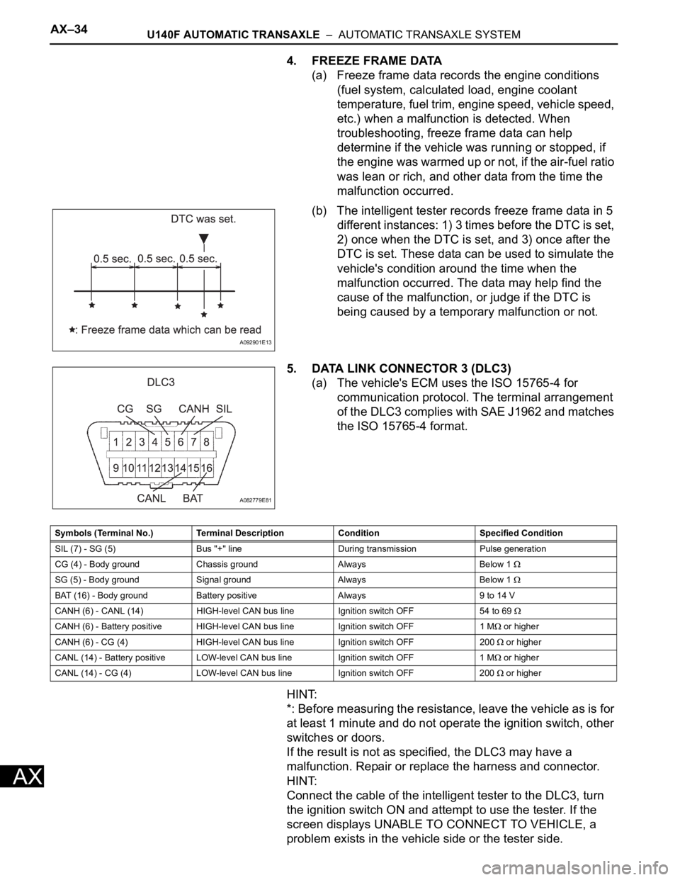
(b) The intelligent tester records freeze frame data in 5
different instances: 1) 3 times before the DTC is set,
2) once when the DTC is set, and 3) once after the
DTC is set. These data can be used to simulate the
vehicle's condition around the time when the
malfunction occurred. The data may help find the
cause of the malfunction, or judge if the DTC is
being caused by a temporary malfunction or not.
5. DATA LINK CONNECTOR 3 (DLC3)
(a) The vehicle's ECM uses the ISO 15765-4 for
communication protocol. The terminal arrangement
of the DLC3 complies with SAE J1962 and matches
the ISO 15765-4 format.
HINT:
*: Before measuring the resistance, leave the vehicle as is for
at least 1 minute and do not operate the ignition switch, other
switches or doors.
If the result is not as specified, the DLC3 may have a
malfunction. Repair or replace the harness and connector.
HINT:
Connect the cable of the intelligent tester to the DLC3, turn
the ignition switch ON and attempt to use the tester. If the
screen displays UNABLE TO CONNECT TO VEHICLE, a
problem exists in the vehicle side or the tester side.
A092901E13
A082779E81
Symbols (Terminal No.) Terminal Description Condition Specified Condition
SIL (7) - SG (5) Bus "+" line During transmission Pulse generation
CG (4) - Body ground Chassis ground Always Below 1
SG (5) - Body ground Signal ground Always Below 1
BAT (16) - Body ground Battery positive Always 9 to 14 V
CANH (6) - CANL (14) HIGH-level CAN bus line Ignition switch OFF 54 to 69
CANH (6) - Battery positive HIGH-level CAN bus line Ignition switch OFF 1 M or higher
CANH (6) - CG (4) HIGH-level CAN bus line Ignition switch OFF 200
or higher
CANL (14) - Battery positive LOW-level CAN bus line Ignition switch OFF 1 M
or higher
CANL (14) - CG (4) LOW-level CAN bus line Ignition switch OFF 200
or higher