2006 TOYOTA RAV4 start rele
[x] Cancel search: start relePage 481 of 2000

2AZ-FE ENGINE CONTROL SYSTEM – SFI SYSTEMES–27
ES
– Air-fuel ratio feedback control is performed.
(b) Drive Pattern for front A/F sensor and HO2 sensor
(1) Connect the intelligent tester to the DLC3.
(2) Turn the ignition switch ON.
(3) Turn the tester ON.
(4) Clear DTCs (see page ES-35).
(5) Start the engine, and warm it up until the ECT
reaches 75
C (167F) or higher.
(6) Drive the vehicle at between 60 km/h (38 mph)
and 120 km/h (75 mph) for at least 10 minutes.
(7) Change the transmission to 2nd gear.
(8) Accelerate the vehicle to 64 km/h (40 mph) or
more by depressing the accelerator pedal for at
least 10 seconds.
(9) Soon after performing step (8) above, release
the accelerator pedal for at least 4 seconds without
depressing the brake pedal, in order to execute fuel-
cut control.
(10) Allow the vehicle to decelerate until the vehicle
speed declines to less than 10 km/h (6 mph).
(11) Repeat steps from (8) through (10) above at
least 3 times in one driving cycle.
(c) Monitor Status
(1) Check the Readiness Monitor status displayed
on the tester.
(2) If the status does not switch to COMPL
(complete), make sure that the preconditions
have been met, and then perform steps from (5)
through (11) in the Drive Pattern above.
5. AIR-FUEL RATIO (A/F) AND HEATED OXYGEN (HO2)
SENSOR HEATER MONITORS (FRONT A/F AND
REAR HO2 SENSOR TYPE)
A121604E06
Page 486 of 2000

ES–322AZ-FE ENGINE CONTROL SYSTEM – SFI SYSTEM
ES
VPA (A9-55) - EPA (A9-59) W - YAccelerator pedal position
sensor (for engine control)Ignition switch ON,
Accelerator pedal released0.5 to 1.1 V
Ignition switch ON,
Accelerator pedal fully depressed2.6 to 4.5 V
VPA2 (A9-56) - EPA2 (A9-60) R - OAccelerator pedal position
sensor (for sensor
malfunctioning detection)Ignition switch ON,
Accelerator pedal released1.2 to 2.0 V
Ignition switch ON,
Accelerator pedal fully depressed3.4 to 5.0 V
VCPA (A9-57) - EPA (A9-59) B - YPower source of
accelerator pedal position
sensor (for VPA)Ignition switch ON 4.5 to 5.5 V
VCP2 (A9-58) - EPA2 (A9-60) L - OPower source of
accelerator pedal position
sensor (for VPA2)Ignition switch ON 4.5 to 5.5 V
HA1A (B30-109) - E04 (B30-46) L - W-B A/F sensor heaterIdling Below 3.0 V
Ignition switch ON 9 to 14 V
A1A+ (B30-112) - E1 (B30-104) B -BR A/F sensor Ignition switch ON 3.3 V*
A1A- (B30-113) - E1 (B30-104) R - BR A/F sensor Ignition switch ON3.0 V*
HT1B (B30-47) - E03 (B30-86) R - W-BHeated oxygen sensor
heaterIdling Below 3.0 V
Ignition switch ON 9 to 14 V
OX1B (B30-64) - EX1B (B30-87) B - BR Heated oxygen sensorEngine speed maintained at 2,500
rpm for 2 minutes after warming up
sensorPulse generation (see
waveform 2)
#10 (B30-108) - E01 (B30-45)
#20 (B30-107) - E01 (B30-45)
#30 (B30-106) - E01 (B30-45)
#40 (B30-105) - E01 (B30-45)L - W-B
G - W-B
B - W-B
W - W-BInjectorIgnition switch ON 9 to 14 V
IdlingPulse generation (see
waveform 3)
KNK1 (B30-110) - EKNK (B30-
111 )B - W Knock sensorEngine speed maintained at 4,000
after warming up enginePulse generation (see
waveform 4)
G2+ (B30-99) - G2- (B30-98) L - Y Camshaft position sensor IdlingPulse generation (see
waveform 5)
NE+ (B30-122) - NE- (B30-121) W - B Crankshaft position sensor IdlingPulse generation (see
waveform 5)
IGT1 (B30-85) - E1 (B30-104)
IGT2 (B30-84) - E1 (B30-104)
IGT3 (B30-83) - E1 (B30-104)
IGT4 (B30-82) - E1 (B30-104)R - BR
P - BR
G - BR
L - BRIgnition coil (ignition
signal)IdlingPulse generation (see
waveform 6)
IGF1 (B30-81) - E1 (B30-104) W - BRIgnition coil (ignition
confirmation signal)Ignition switch ON 4.5 to 5.5 V
IdlingPulse generation (see
waveform 6)
PRG (B30-49) - E1 (B30-104) G - BR Purge VSVIgnition switch ON 9 to 14 V
IdlingPulse generation (see
waveform 7)
SPD (A9-8) - E1 (B30-104) V - BRSpeed signal from
combination meterDriving at 20 km/h (12 mph)Pulse generation (see
waveform 8)
STA (A9-48) - E1 (B30-104) LG - BR Starter signal Cranking 5.5 V or
more
STAR (B30-52) - E1 (B30-104) W - BR Starter relay controlIgnition switch ON Below 1.5 V
Cranking 6.0 V or more
STP (A9-36) - E1 (B30-104) L - BR Stop light switchBrake pedal depressed 7.5 to 14 V
Brake pedal released Below 1.5 V
ST1- (A9-35) - E1 (B30-104) GR - BRStop light switch
(opposite to STP terminal)Ignition switch ON,
Brake pedal depressedBelow 1.5 V
Ignition switch ON,
Brake pedal released7.5 to 14 V
M+ (B30-42) - ME01 (B30-43) B - W-B Throttle actuator Idling with warm enginePulse generation (see
waveform 9) Symbols (Terminal No.) Wiring Colors Terminal Descriptions ConditionsSpecified
Conditions
Page 554 of 2000

ES–302GR-FE ENGINE CONTROL SYSTEM – SFI SYSTEM
ES
– Air-fuel ratio feedback control is performed.
(b) Drive Pattern for front A/F sensor and HO2 sensor
(1) Connect the intelligent tester to the DLC3.
(2) Turn the ignition switch ON.
(3) Turn the tester ON.
(4) Clear DTCs (see page ES-39).
(5) Start the engine, and warm it up until the ECT
reaches 75
C (167F) or higher.
(6) Drive the vehicle at between 60 km/h (38 mph)
and 120 km/h (75 mph) for at least 10 minutes.
(7) Change the transmission to 2nd gear.
(8) Accelerate the vehicle to 64 km/h (40 mph) or
more by depressing the accelerator pedal for at
least 10 seconds.
(9) Soon after performing step (8) above, release
the accelerator pedal for at least 4 seconds without
depressing the brake pedal in order to execute fuel-
cut control.
(10) Allow the vehicle to decelerate until the vehicle
speed declines to less than 10 km/h (6 mph).
(11) Repeat steps from (8) through (10) above at
least 3 times in one driving cycle.
(c) Monitor Status
(1) Check the Readiness Monitor status displayed
on the tester.
(2) If the status does not switch to COMPL
(complete), make sure that the preconditions
have been met, and then perform steps from (5)
through (11) in the Drive Pattern above.
5. AIR-FUEL RATIO (A/F) AND HEATED OXYGEN (HO2)
SENSOR HEATER MONITORS (FRONT A/F AND
REAR HO2 SENSOR TYPE)
A121604E06
Page 560 of 2000

ES–362GR-FE ENGINE CONTROL SYSTEM – SFI SYSTEM
ES
VV2+ (B30-67) - VV2- (B30-90) W - B Variable valve timing
(VVT) sensor (Intake side
(bank 2))Idling Pulse generation
(see waveform 5)
EV1+ (B30-68) - EV1- (B30-91) Y - G Variable valve timing
(VVT) sensor (Exhaust
side (bank 1))Idling Pulse generation
(see waveform 5)
EV2+ (B30-66) - EV2- (B30-89) R - L Variable valve timing
(VVT) sensor (Exhaust
side (bank 2))Idling Pulse generation
(see waveform 5)
NE+ (B30-110) - NE- (B30-111) G - R Crankshaft position sensor Idling Pulse generation (see
waveform 5)
IGT1 (B30-40) - E1 (B30-81)
IGT2 (B30-39) - E1 (B30-81)
IGT3 (B30-38) - E1 (B30-81)
IGT4 (B30-37) - E1 (B30-81)
IGT5 (B30-36) - E1 (B30-81)
IGT6 (B30-35) - E1 (B30-81)W - BR
G-R - BR
G - BR
LG - BR
P - BR
V - BRIgnition coil (ignition
signal)Idling Pulse generation (see
waveform 6)
IGF1 (B30-106) - E1 (B30-81) Y - BR Ignition coil (ignition
confirmation signal)Ignition switch ON 4.5 to 5.5 V
Idling Pulse generation (see
waveform 6)
PRG (B30-108) - E1 (B30-81) LG - BR Purge VSV Ignition switch ON 9 to 14 V
Idling Pulse generation (see
waveform 7)
SPD (A9-8) - E1 (B30-81) V - BR Speed signal from
combination meterDriving at 20 km/h (12 mph) Pulse generation (see
waveform 8)
STA (A9-48) - E1 (B30-81) LG - BR Starter signal Cranking 5.5 V or more
NSW (B30-62) - E1 (B30-81) G-R - BR Starter relay control Ignition switch ON Below 1.5 V
Cranking 6.0 V or more
STP (A9-36) - E1 (B30-81) L - BR Stop light switch Brake pedal depressed 7.5 to 14 V
Brake pedal released Below 1.5 V
ST1- (A9-35) - E1 (B30-81) GR - BR Stop light switch
(opposite to STP terminal)Ignition switch ON,
Brake pedal depressedBelow 1.5 V
Ignition switch ON,
Brake pedal released7.5 to 14 V
M+ (B30-19) - ME01 (B30-20) G - BR Throttle actuator Idling with warm engine Pulse generation (see
waveform 9)
M- (B30-18) - ME01 (B30-20) R - BR Throttle actuator Idling with warm engine Pulse generation (see
waveform 10)
FC (A9-7) - E1 (B30-81) W - BR Fuel pump control Ignition switch ON 9 to 14 V
Idling Below 1.5 V
FPR (B30-59) - E1 (B30-81) W - BR Fuel pump control Cranking 9 to 14 V
FPR (B30-59) - E1 (B30-81) W - BR Fuel pump control Idling 9 to 14 V
W (A9-24) - E1 (B30-81) R - BR MIL Ignition switch ON Below 1.5 V
Idling 9 to 14 V
TC (A9-27) - E1 (B30-81) G - BR Terminal TC of DLC3 Ignition switch ON 9 to 14 V
TACH (A9-15) - E1 (B30-81) GR - BR Engine speed Idling Pulse generation (see
waveform 11)
VPMP (A9-42) - E1 (B30-81) W - BR Vent valve (built into
canister pump module)Ignition switch ON 9 to 14 V
MPMP (A9-34) - E1 (B30-81) B - BR Leak detection pump (built
into canister pump
module)Leak detection pump OFF Below 3 V
Leak detection pump ON 9 to 14 V
VCPP (B30-75) - EPPM (B30-76) V - BR Power source for canister
pressure sensor (specific
voltage)Ignition switch ON 4.5 to 5.5 V Symbol (Terminal No.) Wiring Color Terminal Description Condition Specified Condition
Page 1517 of 2000
BC–14BRAKE CONTROL – VEHICLE STABILITY CONTROL SYSTEM
BC
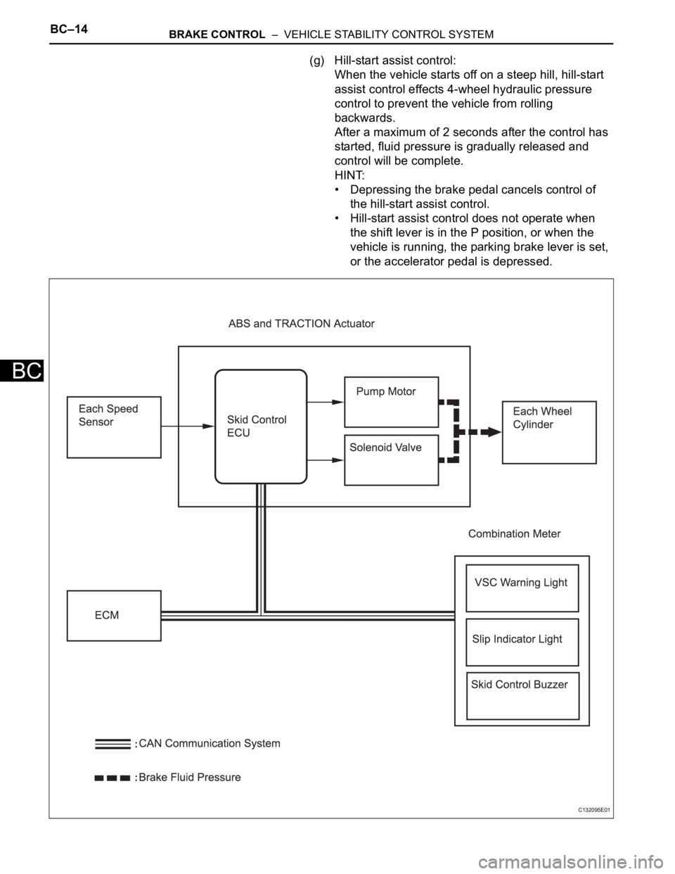
(g) Hill-start assist control:
When the vehicle starts off on a steep hill, hill-start
assist control effects 4-wheel hydraulic pressure
control to prevent the vehicle from rolling
backwards.
After a maximum of 2 seconds after the control has
started, fluid pressure is gradually released and
control will be complete.
HINT:
• Depressing the brake pedal cancels control of
the hill-start assist control.
• Hill-start assist control does not operate when
the shift lever is in the P position, or when the
vehicle is running, the parking brake lever is set,
or the accelerator pedal is depressed.
C132095E01
Page 1518 of 2000

BRAKE CONTROL – VEHICLE STABILITY CONTROL SYSTEMBC–15
BC
(1) Operation description:
When the system is in operation, the following
occurs: 1) the slip indicator light blinks; 2) the
VSC light comes on; and 3) when hill-start assist
control operation starts, the skid control buzzer
sounds once; when hill-start assist control
operation ends, the skid control buzzer sounds
twice.
The VSC warning light comes on when the hill-
start assist control is malfunctioning.
(h) AUTO LSD (Auto Limited Slip Differential) for 2WD:
The AUTO LSD achieves the equivalent functions of
an LSD (Limited Slip Differential) through the use of
a traction control system. When the driver presses
the AUTO LSD switch, this system achieves the
LSD effect by regulating the hydraulic pressure that
acts on the drive wheels and controlling the engine
output in accordance with the amount of pedal effort
applied on the accelerator. The AUTO LSD
operates with the AUTO LSD switch on and the
accelerator pedal depressed.
Auto LSD restrains brake pressure and reduces
differential movement, thus transmitting the drive
torque to the other drive wheel to ensure stability
under the following conditions:
• Wheels run off the road.
• Drive wheels spin in place when starting on a
slope with one wheel on snow/ice.
HINT:
Releasing the accelerator pedal cancels control of
the AUTO LSD system.
Page 1534 of 2000
BRAKE CONTROL – VEHICLE STABILITY CONTROL SYSTEMBC–31
BC
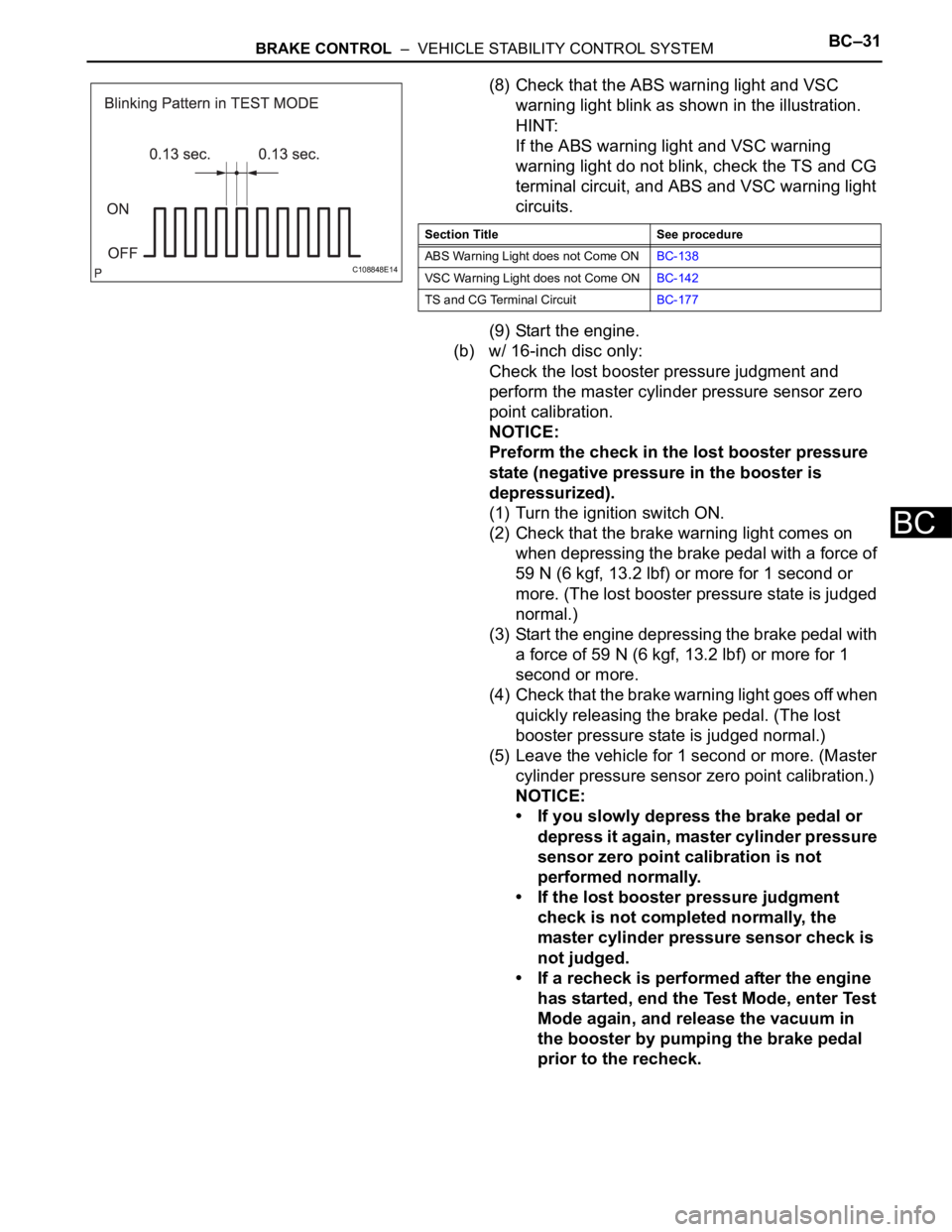
(8) Check that the ABS warning light and VSC
warning light blink as shown in the illustration.
HINT:
If the ABS warning light and VSC warning
warning light do not blink, check the TS and CG
terminal circuit, and ABS and VSC warning light
circuits.
(9) Start the engine.
(b) w/ 16-inch disc only:
Check the lost booster pressure judgment and
perform the master cylinder pressure sensor zero
point calibration.
NOTICE:
Preform the check in the lost booster pressure
state (negative pressure in the booster is
depressurized).
(1) Turn the ignition switch ON.
(2) Check that the brake warning light comes on
when depressing the brake pedal with a force of
59 N (6 kgf, 13.2 lbf) or more for 1 second or
more. (The lost booster pressure state is judged
normal.)
(3) Start the engine depressing the brake pedal with
a force of 59 N (6 kgf, 13.2 lbf) or more for 1
second or more.
(4) Check that the brake warning light goes off when
quickly releasing the brake pedal. (The lost
booster pressure state is judged normal.)
(5) Leave the vehicle for 1 second or more. (Master
cylinder pressure sensor zero point calibration.)
NOTICE:
• If you slowly depress the brake pedal or
depress it again, master cylinder pressure
sensor zero point calibration is not
performed normally.
• If the lost booster pressure judgment
check is not completed normally, the
master cylinder pressure sensor check is
not judged.
• If a recheck is performed after the engine
has started, end the Test Mode, enter Test
Mode again, and release the vacuum in
the booster by pumping the brake pedal
prior to the recheck.
C108848E14
Section Title See procedure
ABS Warning Light does not Come ONBC-138
VSC Warning Light does not Come ONBC-142
TS and CG Terminal CircuitBC-177
Page 1535 of 2000
BC–32BRAKE CONTROL – VEHICLE STABILITY CONTROL SYSTEM
BC
(c) Check the deceleration sensor.
(1) Keep the vehicle stationary on a level surface for
1 second or more.
HINT:
The deceleration sensor check can be
performed together with the following master
cylinder pressure sensor check.
(d) Check the master cylinder pressure sensor.
(1) Leave the vehicle in a stationary condition and
release the brake pedal for 1 second or more,
and quickly depress the brake pedal with a force
of 98 N (10 kgf, 22 lbf) or more for 1 second.
Check that the ABS warning light remains
illuminated for 3 seconds.
HINT:
• Ensure that the ABS warning light comes on.
• While the ABS warning light remains
illuminated, continue depressing the brake
pedal with a force of 98 N (10 kgf, 22 lbf) or
more.
• The ABS warning light comes on for 3
seconds every time the brake pedal operation
above is performed.
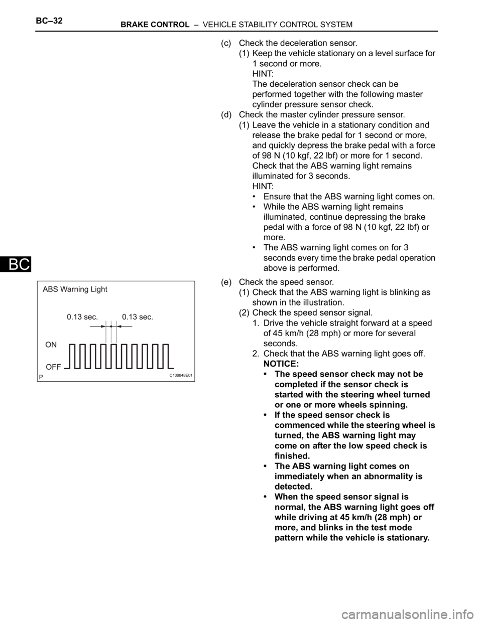
(e) Check the speed sensor.
(1) Check that the ABS warning light is blinking as
shown in the illustration.
(2) Check the speed sensor signal.
1. Drive the vehicle straight forward at a speed
of 45 km/h (28 mph) or more for several
seconds.
2. Check that the ABS warning light goes off.
NOTICE:
• The speed sensor check may not be
completed if the sensor check is
started with the steering wheel turned
or one or more wheels spinning.
• If the speed sensor check is
commenced while the steering wheel is
turned, the ABS warning light may
come on after the low speed check is
finished.
• The ABS warning light comes on
immediately when an abnormality is
detected.
• When the speed sensor signal is
normal, the ABS warning light goes off
while driving at 45 km/h (28 mph) or
more, and blinks in the test mode
pattern while the vehicle is stationary.
C108848E01