Page 609 of 2000
2AZ-FE ENGINE MECHANICAL – CYLINDER HEADEM–65
EM
(b) Using SST, compress the spring, then remove the 2
retainer locks.
SST 09202-70020 (09202-00010)
(c) Remove the retainer, spring and valve from the
cylinder head.
HINT:
Arrange the removed parts in the correct order.
10. REMOVE VALVE SPRING SEAT
(a) Using compressed air and a magnetic finger,
remove the spring seat by blowing air.
HINT:
Arrange the valves, valve springs, spring seats and
spring retainers in the correct order.
11. REMOVE VALVE STEM OIL SEAL
(a) Using needle-nose pliers, remove the 16 oil seals.
A098133E01
A114363E01
A014192E01
A013356E01
Page 632 of 2000
EM–882AZ-FE ENGINE MECHANICAL – CYLINDER HEAD
EM
47. CHECK FOR ENGINE OIL LEAKS
48. CHECK FOR EXHAUST GAS LEAKS
49. INSPECT IGNITION TIMING (See page EM-1)
50. INSPECT ENGINE IDLING SPEED (See page EM-2)
51. INSPECT COMPRESSION (See page EM-3)
52. INSPECT CO/HC (See page EM-4)
53. INSTALL NO. 1 ENGINE COVER (See page EM-43)
54. INSTALL FRONT FENDER APRON RH
55. INSTALL NO. 1 ENGINE UNDER COVER
56. INSTALL FRONT WHEEL RH
57. INSTALL RADIATOR SUPPORT OPENING COVER
REPAIR
1. REPAIR VALVE SEATS
(a) If the seating is too high on the valve face, use 30
and 45
cutters to correct the seat.
(b) If the seating is too low on the valve face, use 75
and 45
cutters to correct the seat.
Standard width
(c) Lap the valve and valve seat by hand with an
abrasive compound.
(d) Recheck the valve seating position.
A128227E01
Item Standard Condition
Intake 1.0 to 1.4 mm (0.0394 to 0.0551 in.)
Exhaust 1.2 to 1.6 mm (0.0427 to 0.0630 in.)
Page 751 of 2000

EM–1142GR-FE ENGINE MECHANICAL – ENGINE UNIT
EM
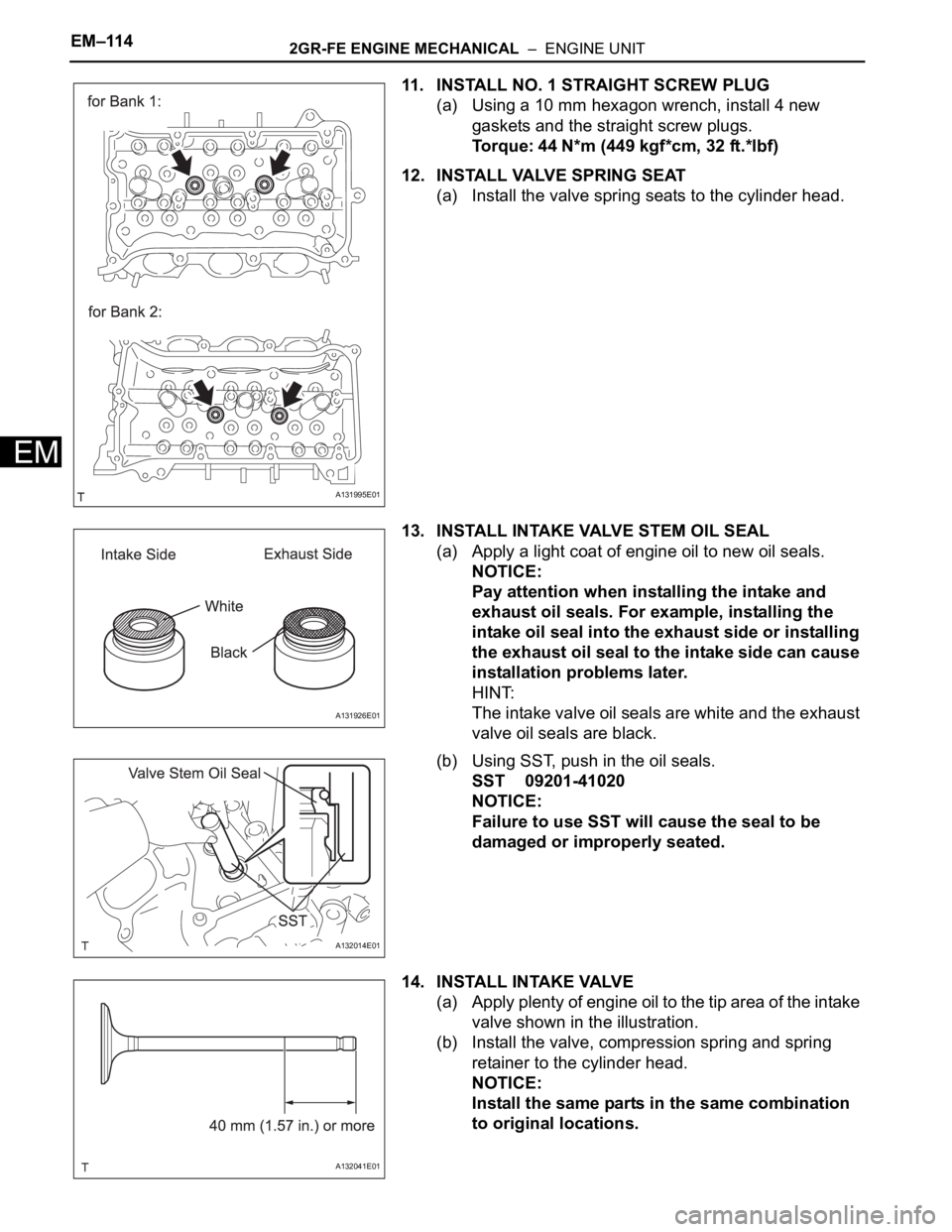
11. INSTALL NO. 1 STRAIGHT SCREW PLUG
(a) Using a 10 mm hexagon wrench, install 4 new
gaskets and the straight screw plugs.
Torque: 44 N*m (449 kgf*cm, 32 ft.*lbf)
12. INSTALL VALVE SPRING SEAT
(a) Install the valve spring seats to the cylinder head.
13. INSTALL INTAKE VALVE STEM OIL SEAL
(a) Apply a light coat of engine oil to new oil seals.
NOTICE:
Pay attention when installing the intake and
exhaust oil seals. For example, installing the
intake oil seal into the exhaust side or installing
the exhaust oil seal to the intake side can cause
installation problems later.
HINT:
The intake valve oil seals are white and the exhaust
valve oil seals are black.
(b) Using SST, push in the oil seals.
SST 09201-41020
NOTICE:
Failure to use SST will cause the seal to be
damaged or improperly seated.
14. INSTALL INTAKE VALVE
(a) Apply plenty of engine oil to the tip area of the intake
valve shown in the illustration.
(b) Install the valve, compression spring and spring
retainer to the cylinder head.
NOTICE:
Install the same parts in the same combination
to original locations.
A131995E01
A131926E01
A132014E01
A132041E01