Page 873 of 2000
CO–442GR-FE COOLING – RADIATOR
CO
27. INSTALL NO. 1 ENGINE UNDER COVER (See page
EM-41)
Page 931 of 2000
CH–122GR-FE CHARGING – GENERATOR
CH
REMOVAL
1. REMOVE RADIATOR ASSEMBLY
(a) Remove the radiator (see page CO-36).
2. REMOVE FRONT WHEEL RH
3. REMOVE ENGINE UNDER COVER REAR RH (See
page EM-21)
4. REMOVE FRONT SUSPENSION MEMBER
REINFORCEMENT RH (See page EM-7)
5. REMOVE RADIATOR RESERVOIR TANK (See page
CO-19)
6. REMOVE FAN AND GENERATOR V BELT (See page
EM-8)
7. REMOVE GENERATOR ASSEMBLY
(a) Disconnect the 2 wire harness clamps.
(b) Remove the terminal cap.
(c) Remove the nut and disconnect the generator wire
from terminal B.
(d) Disconnect the generator connector from the
generator.
(e) Remove the bolt from the cylinder block.
A132430
A132431
A132432E01
Page 939 of 2000
CH–202GR-FE CHARGING – GENERATOR
CH
(b) Install the bolt to the cylinder block.
Torque: 20 N*m (204 kgf*cm, 15 ft.*lbf)
(c) Connect the generator connector to the generator.
(d) Connect the generator wire with the nut.
Torque: 9.8 N*m (100 kgf*cm, 88 in.*lbf)
(e) Install the terminal cap.
(f) Connect the 2 wire harness clamps.
2. INSTALL FAN AND GENERATOR V BELT (See page
EM-8)
3. INSTALL RADIATOR RESERVOIR TANK (See page
CO-21)
4. INSTALL FRONT SUSPENSION MEMBER
REINFORCEMENT RH (See page EM-9)
5. INSTALL ENGINE UNDER COVER REAR RH (See
page EM-41)
6. INSTALL FRONT WHEEL RH
7. INSTALL RADIATOR ASSEMBLY
(a) Install the radiator (see page CO-40).
A132432E01
A132431
A132430
Page 1651 of 2000

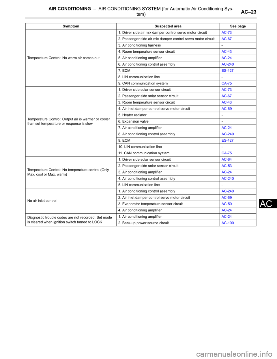
AIR CONDITIONING – AIR CONDITIONING SYSTEM (for Automatic Air Conditioning Sys-
tem)AC–23
AC
Temperature Control: No warm air comes out1. Driver side air mix damper control servo motor circuitAC-73
2. Passenger side air mix damper control servo motor circuitAC-67
3. Air conditioning harness -
4. Room temperature sensor circuitAC-43
5. Air conditioning amplifierAC-24
6. Air conditioning control assemblyAC-240
7. ECMES-427
8. LIN communication line -
9. CAN communication systemCA-75
Temperature Control: Output air is warmer or cooler
than set temperature or response is slow1. Driver side solar sensor circuitAC-73
2. Passenger side solar sensor circuitAC-67
3. Room temperature sensor circuitAC-43
4. Air inlet damper control servo motor circuitAC-69
5. Heater radiator -
6. Expansion valve -
7. Air conditioning amplifierAC-24
8. Air conditioning control assemblyAC-240
9. ECMES-427
10. LIN communication line -
11. CAN communication systemCA-75
Temperature Control: No temperature control (Only
Max. cool or Max. warm)1. Driver side solar sensor circuitAC-64
2. Passenger side solar sensor circuitAC-53
3. Air conditioning amplifierAC-24
4. Air conditioning control assemblyAC-240
5. LIN communication line -
No air inlet control1. Air conditioning control assemblyAC-240
2. Air inlet damper control servo motor circuitAC-69
3. Evaporator temperature sensor circuitAC-50
4. Air conditioning amplifierAC-24
Diagnostic trouble codes are not recorded. Set mode
is cleared when ignition switch turned to LOCK1. Air conditioning amplifierAC-24
2. Back-up power source circuitAC-100 Symptom Suspected area See page
Page 1653 of 2000

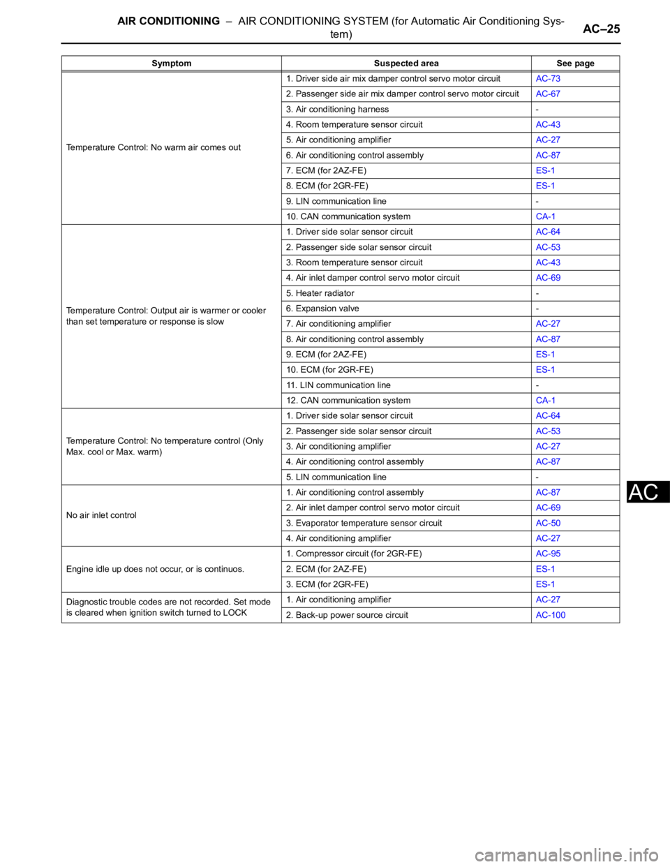
AIR CONDITIONING – AIR CONDITIONING SYSTEM (for Automatic Air Conditioning Sys-
tem)AC–25
AC
Temperature Control: No warm air comes out1. Driver side air mix damper control servo motor circuitAC-73
2. Passenger side air mix damper control servo motor circuitAC-67
3. Air conditioning harness -
4. Room temperature sensor circuitAC-43
5. Air conditioning amplifierAC-27
6. Air conditioning control assemblyAC-87
7. ECM (for 2AZ-FE)ES-1
8. ECM (for 2GR-FE)ES-1
9. LIN communication line -
10. CAN communication systemCA-1
Temperature Control: Output air is warmer or cooler
than set temperature or response is slow1. Driver side solar sensor circuitAC-64
2. Passenger side solar sensor circuitAC-53
3. Room temperature sensor circuitAC-43
4. Air inlet damper control servo motor circuitAC-69
5. Heater radiator -
6. Expansion valve -
7. Air conditioning amplifierAC-27
8. Air conditioning control assemblyAC-87
9. ECM (for 2AZ-FE)ES-1
10. ECM (for 2GR-FE)ES-1
11. LIN communication line -
12. CAN communication systemCA-1
Temperature Control: No temperature control (Only
Max. cool or Max. warm)1. Driver side solar sensor circuitAC-64
2. Passenger side solar sensor circuitAC-53
3. Air conditioning amplifierAC-27
4. Air conditioning control assemblyAC-87
5. LIN communication line -
No air inlet control1. Air conditioning control assemblyAC-87
2. Air inlet damper control servo motor circuitAC-69
3. Evaporator temperature sensor circuitAC-50
4. Air conditioning amplifierAC-27
Engine idle up does not occur, or is continuos.1. Compressor circuit (for 2GR-FE)AC-95
2. ECM (for 2AZ-FE)ES-1
3. ECM (for 2GR-FE)ES-1
Diagnostic trouble codes are not recorded. Set mode
is cleared when ignition switch turned to LOCK1. Air conditioning amplifierAC-27
2. Back-up power source circuitAC-100 Symptom Suspected area See page
Page 1661 of 2000
AIR CONDITIONING – AIR MIX CONTROL SERVO MOTOR (for Automatic Air Conditioning
System)AC–215
AC
INSTALLATION
1. INSTALL AIR MIX CONTROL SERVO MOTOR (See
page AC-196)
2. INSTALL AIR CONDITIONING UNIT
(a) Install the air conditioning radiator (see page AC-
197).
Page 1666 of 2000

AIR CONDITIONING – CONDENSERAC–225
AC
REMOVAL
1. DISCHARGE REFRIGERANT FROM
REFRIGERATION SYSTEM (See page AC-172)
2. DISCONNECT CABLE FROM NEGATIVE BATTERY
TERMINAL
CAUTION:
Wait at least 90 seconds after disconnecting the
cable from the negative (-) battery terminal to
prevent airbag and seat belt pretensioner activation.
3. REMOVE FRONT BUMPER COVER
(a) Remove front bumper cover (see page ET-4).
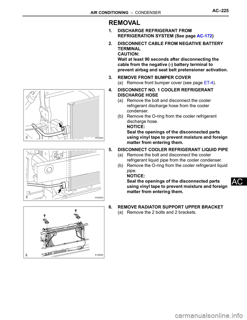
4. DISCONNECT NO. 1 COOLER REFRIGERANT
DISCHARGE HOSE
(a) Remove the bolt and disconnect the cooler
refrigerant discharge hose from the cooler
condenser.
(b) Remove the O-ring from the cooler refrigerant
discharge hose.
NOTICE:
Seal the openings of the disconnected parts
using vinyl tape to prevent moisture and foreign
matter from entering them.
5. DISCONNECT COOLER REFRIGERANT LIQUID PIPE
(a) Remove the bolt and disconnect the cooler
refrigerant liquid pipe from the cooler condenser.
(b) Remove the O-ring from the cooler refrigerant liquid
pipe.
NOTICE:
Seal the openings of the disconnected parts
using vinyl tape to prevent moisture and foreign
matter from entering them.
6. REMOVE RADIATOR SUPPORT UPPER BRACKET
(a) Remove the 2 bolts and 2 brackets.
H102042
H102043
E126555
Page 1669 of 2000

AC–228AIR CONDITIONING – CONDENSER
AC
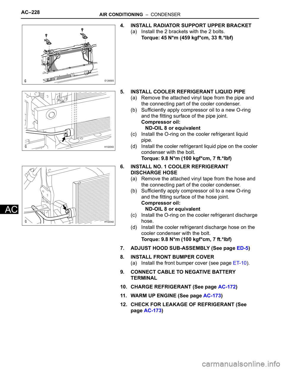
4. INSTALL RADIATOR SUPPORT UPPER BRACKET
(a) Install the 2 brackets with the 2 bolts.
Torque: 45 N*m (459 kgf*cm, 33 ft.*lbf)
5. INSTALL COOLER REFRIGERANT LIQUID PIPE
(a) Remove the attached vinyl tape from the pipe and
the connecting part of the cooler condenser.
(b) Sufficiently apply compressor oil to a new O-ring
and the fitting surface of the pipe joint.
Compressor oil:
ND-OIL 8 or equivalent
(c) Install the O-ring on the cooler refrigerant liquid
pipe.
(d) Install the cooler refrigerant liquid pipe on the cooler
condenser with the bolt.
Torque: 9.8 N*m (100 kgf*cm, 7 ft.*lbf)
6. INSTALL NO. 1 COOLER REFRIGERANT
DISCHARGE HOSE
(a) Remove the attached vinyl tape from the hose and
the connecting part of the cooler condenser.
(b) Sufficiently apply compressor oil to a new O-ring
and the fitting surface of the hose joint.
Compressor oil:
ND-OIL 8 or equivalent
(c) Install the O-ring on the cooler refrigerant discharge
hose.
(d) Install the cooler refrigerant discharge hose on the
cooler condenser with the bolt.
Torque: 9.8 N*m (100 kgf*cm, 7 ft.*lbf)
7. ADJUST HOOD SUB-ASSEMBLY (See page ED-5)
8. INSTALL FRONT BUMPER COVER
(a) Install the front bumper cover (see page ET-10).
9. CONNECT CABLE TO NEGATIVE BATTERY
TERMINAL
10. CHARGE REFRIGERANT (See page AC-172)
11. WARM UP ENGINE (See page AC-173)
12. CHECK FOR LEAKAGE OF REFRIGERANT (See
page AC-173)
E126555
H102043
H102042