2006 TOYOTA RAV4 checking oil
[x] Cancel search: checking oilPage 382 of 2000

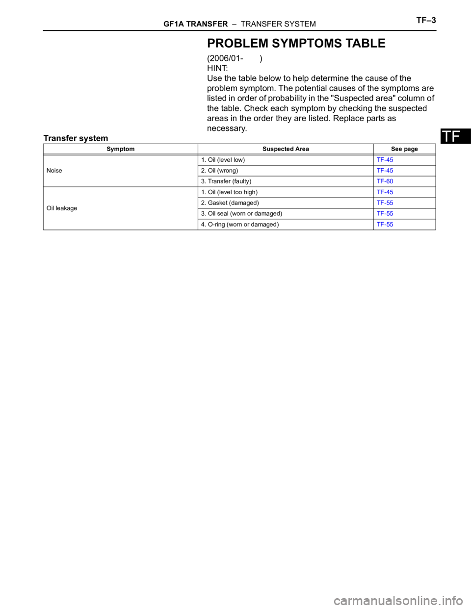
GF1A TRANSFER – TRANSFER SYSTEMTF–3
TF
PROBLEM SYMPTOMS TABLE
(2006/01- )
HINT:
Use the table below to help determine the cause of the
problem symptom. The potential causes of the symptoms are
listed in order of probability in the "Suspected area" column of
the table. Check each symptom by checking the suspected
areas in the order they are listed. Replace parts as
necessary.
Transfer system
Symptom Suspected Area See page
Noise1. Oil (level low)TF-45
2. Oil (wrong)TF-45
3. Transfer (faulty)TF-60
Oil leakage1. Oil (level too high)TF-45
2. Gasket (damaged)TF-55
3. Oil seal (worn or damaged)TF-55
4. O-ring (worn or damaged)TF-55
Page 415 of 2000

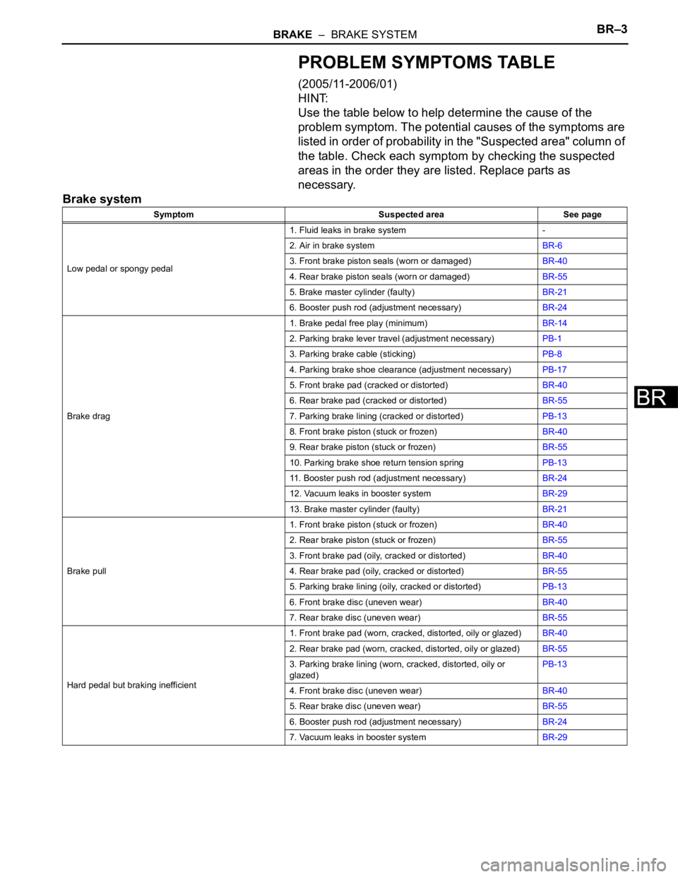
BRAKE – BRAKE SYSTEMBR–3
BR
PROBLEM SYMPTOMS TABLE
(2005/11-2006/01)
HINT:
Use the table below to help determine the cause of the
problem symptom. The potential causes of the symptoms are
listed in order of probability in the "Suspected area" column of
the table. Check each symptom by checking the suspected
areas in the order they are listed. Replace parts as
necessary.
Brake system
Symptom Suspected area See page
Low pedal or spongy pedal1. Fluid leaks in brake system -
2. Air in brake systemBR-6
3. Front brake piston seals (worn or damaged)BR-40
4. Rear brake piston seals (worn or damaged)BR-55
5. Brake master cylinder (faulty)BR-21
6. Booster push rod (adjustment necessary)BR-24
Brake drag1. Brake pedal free play (minimum)BR-14
2. Parking brake lever travel (adjustment necessary)PB-1
3. Parking brake cable (sticking)PB-8
4. Parking brake shoe clearance (adjustment necessary)PB-17
5. Front brake pad (cracked or distorted)BR-40
6. Rear brake pad (cracked or distorted)BR-55
7. Parking brake lining (cracked or distorted)PB-13
8. Front brake piston (stuck or frozen)BR-40
9. Rear brake piston (stuck or frozen)BR-55
10. Parking brake shoe return tension springPB-13
11. Booster push rod (adjustment necessary)BR-24
12. Vacuum leaks in booster systemBR-29
13. Brake master cylinder (faulty)BR-21
Brake pull1. Front brake piston (stuck or frozen)BR-40
2. Rear brake piston (stuck or frozen)BR-55
3. Front brake pad (oily, cracked or distorted)BR-40
4. Rear brake pad (oily, cracked or distorted)BR-55
5. Parking brake lining (oily, cracked or distorted)PB-13
6. Front brake disc (uneven wear)BR-40
7. Rear brake disc (uneven wear)BR-55
Hard pedal but braking inefficient1. Front brake pad (worn, cracked, distorted, oily or glazed)BR-40
2. Rear brake pad (worn, cracked, distorted, oily or glazed)BR-55
3. Parking brake lining (worn, cracked, distorted, oily or
glazed)PB-13
4. Front brake disc (uneven wear)BR-40
5. Rear brake disc (uneven wear)BR-55
6. Booster push rod (adjustment necessary)BR-24
7. Vacuum leaks in booster systemBR-29
Page 485 of 2000

2AZ-FE ENGINE CONTROL SYSTEM – SFI SYSTEMES–31
ES
TERMINALS OF ECM
HINT:
The standard normal voltage between each pair of ECM
terminals is shown in the table below. The appropriate
conditions for checking each pair of terminals are also
indicated. The result of checks should be compared with the
standard normal voltage for that pair of terminals, displayed in
the Specified Condition column. The illustration above can be
used as a reference to identify the ECM terminal locations.
A107881E05
Symbols (Terminal No.) Wiring Colors Terminal Descriptions ConditionsSpecified
Conditions
BATT (A9-20) - E1 (B30-104) W - BRBattery (for measuring
battery voltage and for
ECM memory)Always 9 to 14 V
+BM (A9-3) - E1 (B30-104) LG - BRPower source of throttle
actuatorAlways 9 to 14 V
IGSW (A9-28) - E1 (B30-104) B - BR Ignition switch Ignition switch ON 9 to 14 V
+B (A9-2) - E1 (B30-104) B - BR Power source of ECM Ignition switch ON 9 to 14 V
+B2 (A9-1) - E1 (B30-104) B - BR Power source of ECM Ignition switch ON 9 to 14 V
OC1+ (B30-100) - OC1- (B30-
123)BR - LCamshaft timing oil control
valve (OCV)IdlingPulse generation (see
waveform 1)
MREL (A9-44) - E1 (B30-104) O - BR EFI relay Ignition switch ON 9 to 14 V
VG (B30-118) - E2G (B30-116) R - LG Mass air flow meterIdling, Shift lever position P or N, A/
C switch OFF0.5 to 3.0 V
THA (B30-65) - ETHA (B30-88) W - BRIntake air temperature
sensorIdling, Intake air temperature 20
C
(68
F)0.5 to 3.4 V
THW (B30-97) - ETHW (B30-96) GR - BREngine coolant
temperature sensorIdling, Engine coolant temperature
80
C (176F)0.2 to 1.0 V
VCTA (B30-67) - ETA (B30-91) Y - BRPower source of throttle
position sensor (specific
voltage)Ignition switch ON 4.5 to 5.5 V
VTA1 (B30-115) - ETA (B30-91) G - BRThrottle position sensor
(for engine control)Ignition switch ON,
Throttle valve fully closed0.5 to 1.1 V
Ignition switch ON,
Throttle valve fully open3.3 to 4.9 V
VTA2 (B30-114) - ETA (B30-91) L - BRThrottle position sensor
(for sensor malfunction
detection)Ignition switch ON,
Throttle valve fully closed2.1 to 3.1 V
Ignition switch ON,
Throttle valve fully open4.6 to 5.0 V
Page 558 of 2000

ES–342GR-FE ENGINE CONTROL SYSTEM – SFI SYSTEM
ES
TERMINALS OF ECM
1. CHECK ECM
(a) Measure the voltage of the ECM connector.
HINT:
The standard normal voltage between each pair of
ECM terminals is shown in the table below. The
appropriate conditions for checking each pair of
terminals are also indicated. The result of checks
should be compared with the standard normal
voltage for that pair of terminals, displayed in the
Specified Condition column. The illustration above
can be used as a reference to identify the ECM
terminal locations.
A107881E05
Symbol (Terminal No.) Wiring Color Terminal Description Condition Specified Condition
BATT (A9-20) - E1 (B30-81) W - BR Battery (for measuring
battery voltage and for
ECM memory)Always 9 to 14 V
+BM (A9-3) - E1 (B30-81) LG - BR Power source of throttle
actuatorAlways 9 to 14 V
IGSW (A9-28) - E1 (B30-81) B - BR Ignition switch Ignition switch ON 9 to 14 V
+B (A9-2) - E1 (B30-81) B - BR Power source of ECM Ignition switch ON 9 to 14 V
+B2 (A9-1) - E1 (B30-81) B - BR Power source of ECM Ignition switch ON 9 to 14 V
OC1+ (B30-58) - OC1- (B30-57) W - B Camshaft timing oil control
valve (OCV)Ignition switch ON Pulse generation (see
waveform 1)
OC2+ (B30-52) - OC2- (B30-51) BR - B Camshaft timing oil control
valve (OCV) (Intake side
(bank 2))Ignition switch ON Pulse generation
(see waveform 1)
OE1+ (B30-56) - OE1- (B30-55) R - LG Camshaft timing oil control
valve (OCV) (Exhaust side
(bank 1))Ignition switch ON Pulse generation
(see waveform 1)
OE2+ (B30-50) - OE2- (B30-49) W - B Camshaft timing oil control
valve (OCV) (Exhaust side
(bank 2))Ignition switch ON Pulse generation
(see waveform 1)
MREL (A9-44) - E1 (B30-81) O - BR EFI relay Ignition switch ON 9 to 14 V
VG (B30-72) - E2G (B30-73) GR - L-G Mass air flow meter Idling, Shift lever position P or N, A/
C switch OFF0.5 to 3.0 V
THA (B30-71) - ETHA (B30-74) P - G-R Intake air temperature
sensorIdling, Intake air temperature 20
C
(68F)0.5 to 3.4 V
Page 885 of 2000

2AZ-FE IGNITION – IGNITION SYSTEMIG–5
IG
ON-VEHICLE INSPECTION
1. CHECK IGNITION COIL ASSEMBLY AND PERFORM
SPARK TEST
NOTICE:
In this section, the terms "cold" and "hot" refer to
the temperature of the coils. "Cold" means
approximately -10 to 50
C (14 to 122F). "Hot" means
approximately 50 to 100
C (122 to 212F).
(a) Check the DTCs.
NOTICE:
If a DTC is present, perform troubleshooting in
accordance with the procedure for that DTC.
(b) Check that sparks occur.
(1) Remove the No. 1 engine cover.
(2) Remove the bolt and ignition coil.
(3) Using a 16 mm spark plug wrench, remove the
spark plug.
(4) Disconnect the 4 fuel injector connectors.
(5) Install the spark plug into the ignition coil, and
then connect the ignition coil connectors.
(6) Ground the spark plug.
(7) Check that sparks occur at the spark plug while
the engine is being cranked.
NOTICE:
• Be sure to ground the spark plugs when
checking them.
• If the ignition coil has been struck or
dropped, replace it.
• Do not crank the engine for more than 2
seconds.
If sparks do not occur, Perform the spark test.
(8) Using a 16 mm plug wrench, install the spark
plug.
Torque: 25 N*m (254 kgf*cm, 18 ft.*lbf)
A124849E01
A097448E01
A124396
Page 895 of 2000

2GR-FE IGNITION – IGNITION SYSTEMIG–5
IG
ON-VEHICLE INSPECTION
1. CHECK IGNITION COIL ASSEMBLY AND PERFORM
SPARK TEST
NOTICE:
In this section, the terms "Cold" and "Hot" refer to
the temperature of the sensor. "Cold" means
approximately -10 to 50
C (14 to 122F). "Hot" means
approximately 50 to 100
C (122 to 212F).
(a) Check the DTCs.
NOTICE:
If a DTC is present, perform troubleshooting in
accordance with the procedure for that DTC.
(b) Check that sparks occur.
(1) Remove the V-bank cover.
(2) Remove the intake air surge tank (see page
EM-27).
(3) Remove the bolt and ignition coil.
(4) Using a 16 mm spark plug wrench, remove the
spark plug.
(5) Disconnect the 6 fuel injector connectors.
(6) Install the spark plug into the ignition coil, and
then connect the ignition coil connectors.
(7) Ground the spark plug.
(8) Check that sparks occur at the spark plug while
the engine is being cranked.
NOTICE:
• Be sure to ground the spark plugs when
checking them.
• If the ignition coil has been struck or
dropped, replace it.
• Do not crank the engine for more than 2
seconds.
If sparks do not occur, perform troubleshooting
using the spark test flowchart.
(9) Using a 16 mm plug wrench, install the spark
plug.
Torque: 25 N*m (254 kgf*cm, 18 ft.*lbf)
(10) Install the ignition coil with the bolt.
Torque: 10 N*m (102 kgf*cm, 7 ft.*lbf)
(11) Connect the 6 fuel injector connectors.
(12) Install the intake air surge tank (see page EM-
34).
(13) Install the V-bank cover.
A136823
A136826
Page 1448 of 2000

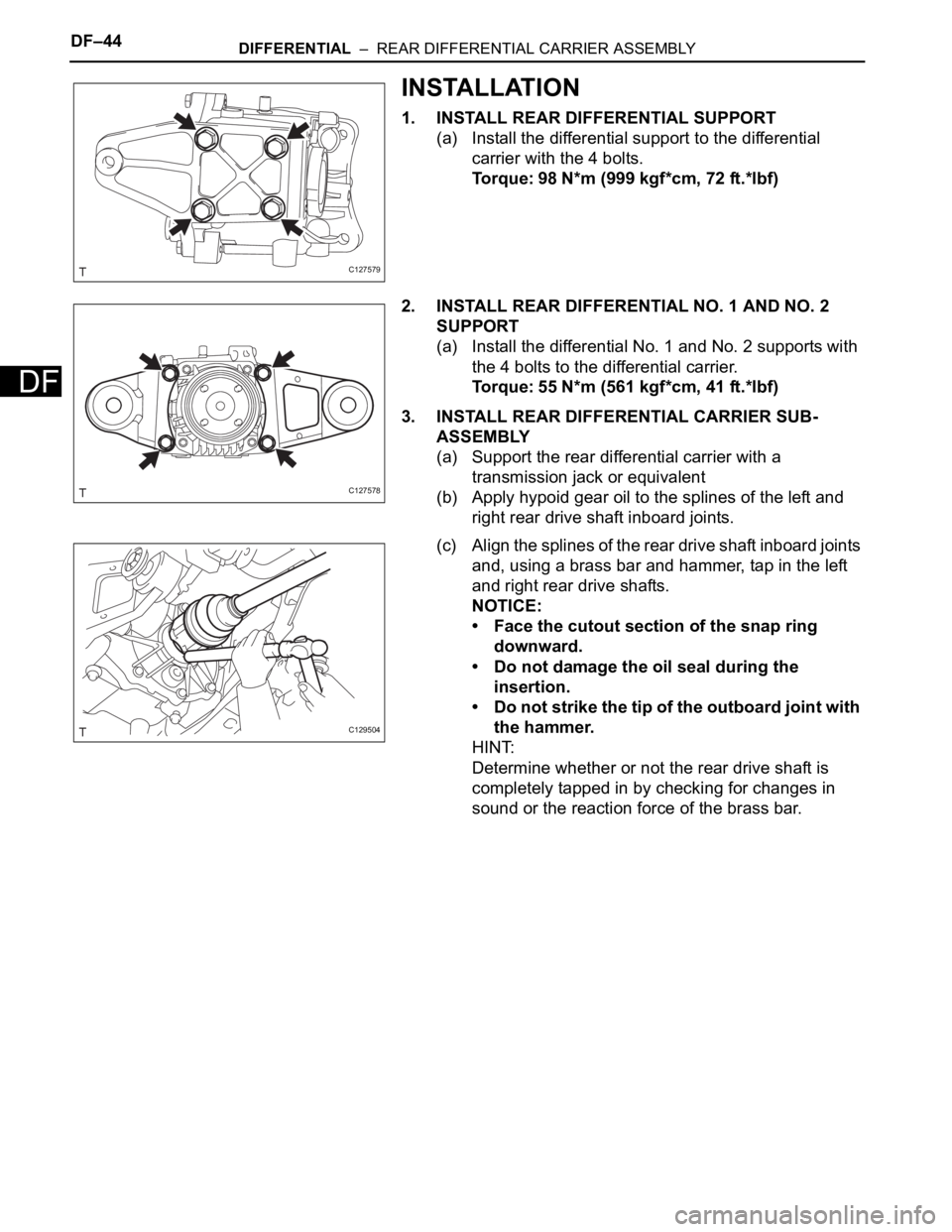
DF–44DIFFERENTIAL – REAR DIFFERENTIAL CARRIER ASSEMBLY
DF
INSTALLATION
1. INSTALL REAR DIFFERENTIAL SUPPORT
(a) Install the differential support to the differential
carrier with the 4 bolts.
Torque: 98 N*m (999 kgf*cm, 72 ft.*lbf)
2. INSTALL REAR DIFFERENTIAL NO. 1 AND NO. 2
SUPPORT
(a) Install the differential No. 1 and No. 2 supports with
the 4 bolts to the differential carrier.
Torque: 55 N*m (561 kgf*cm, 41 ft.*lbf)
3. INSTALL REAR DIFFERENTIAL CARRIER SUB-
ASSEMBLY
(a) Support the rear differential carrier with a
transmission jack or equivalent
(b) Apply hypoid gear oil to the splines of the left and
right rear drive shaft inboard joints.
(c) Align the splines of the rear drive shaft inboard joints
and, using a brass bar and hammer, tap in the left
and right rear drive shafts.
NOTICE:
• Face the cutout section of the snap ring
downward.
• Do not damage the oil seal during the
insertion.
• Do not strike the tip of the outboard joint with
the hammer.
HINT:
Determine whether or not the rear drive shaft is
completely tapped in by checking for changes in
sound or the reaction force of the brass bar.
C127579
C127578
C129504
Page 1565 of 2000

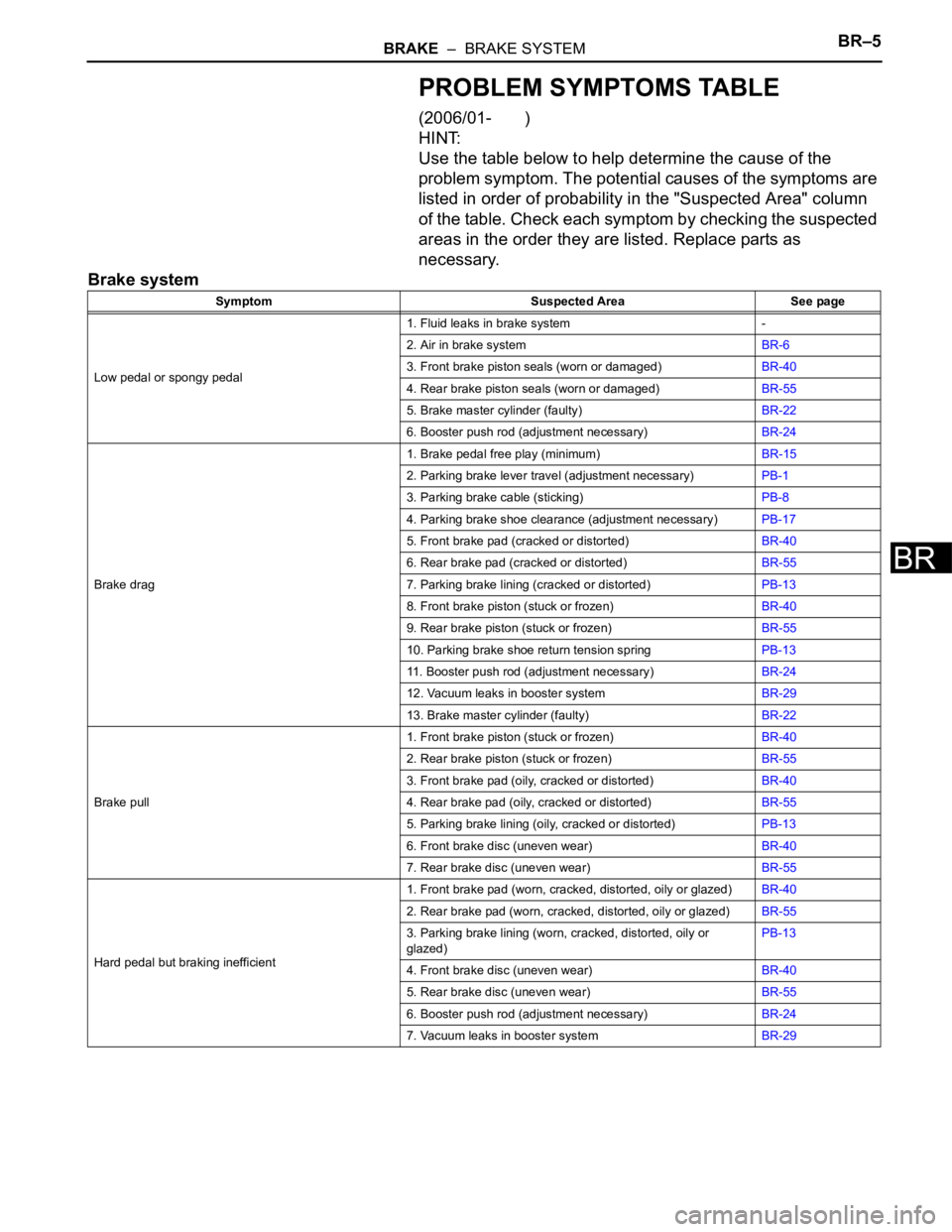
BRAKE – BRAKE SYSTEMBR–5
BR
PROBLEM SYMPTOMS TABLE
(2006/01- )
HINT:
Use the table below to help determine the cause of the
problem symptom. The potential causes of the symptoms are
listed in order of probability in the "Suspected Area" column
of the table. Check each symptom by checking the suspected
areas in the order they are listed. Replace parts as
necessary.
Brake system
Symptom Suspected Area See page
Low pedal or spongy pedal1. Fluid leaks in brake system -
2. Air in brake systemBR-6
3. Front brake piston seals (worn or damaged)BR-40
4. Rear brake piston seals (worn or damaged)BR-55
5. Brake master cylinder (faulty)BR-22
6. Booster push rod (adjustment necessary)BR-24
Brake drag1. Brake pedal free play (minimum)BR-15
2. Parking brake lever travel (adjustment necessary)PB-1
3. Parking brake cable (sticking)PB-8
4. Parking brake shoe clearance (adjustment necessary)PB-17
5. Front brake pad (cracked or distorted)BR-40
6. Rear brake pad (cracked or distorted)BR-55
7. Parking brake lining (cracked or distorted)PB-13
8. Front brake piston (stuck or frozen)BR-40
9. Rear brake piston (stuck or frozen)BR-55
10. Parking brake shoe return tension springPB-13
11. Booster push rod (adjustment necessary)BR-24
12. Vacuum leaks in booster systemBR-29
13. Brake master cylinder (faulty)BR-22
Brake pull1. Front brake piston (stuck or frozen)BR-40
2. Rear brake piston (stuck or frozen)BR-55
3. Front brake pad (oily, cracked or distorted)BR-40
4. Rear brake pad (oily, cracked or distorted)BR-55
5. Parking brake lining (oily, cracked or distorted)PB-13
6. Front brake disc (uneven wear)BR-40
7. Rear brake disc (uneven wear)BR-55
Hard pedal but braking inefficient1. Front brake pad (worn, cracked, distorted, oily or glazed)BR-40
2. Rear brake pad (worn, cracked, distorted, oily or glazed)BR-55
3. Parking brake lining (worn, cracked, distorted, oily or
glazed)PB-13
4. Front brake disc (uneven wear)BR-40
5. Rear brake disc (uneven wear)BR-55
6. Booster push rod (adjustment necessary)BR-24
7. Vacuum leaks in booster systemBR-29