2006 TOYOTA RAV4 door lock
[x] Cancel search: door lockPage 209 of 2000
IN–26INTRODUCTION – REPAIR INSTRUCTION
IN
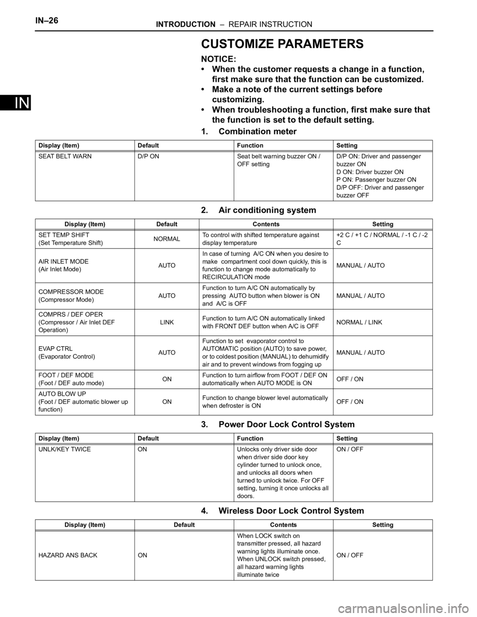
CUSTOMIZE PARAMETERS
NOTICE:
• When the customer requests a change in a function,
first make sure that the function can be customized.
• Make a note of the current settings before
customizing.
• When troubleshooting a function, first make sure that
the function is set to the default setting.
1. Combination meter
2. Air conditioning system
3. Power Door Lock Control System
4. Wireless Door Lock Control System
Display (Item) Default Function Setting
SEAT BELT WARN D/P ON Seat belt warning buzzer ON /
OFF settingD/P ON: Driver and passenger
buzzer ON
D ON: Driver buzzer ON
P ON: Passenger buzzer ON
D/P OFF: Driver and passenger
buzzer OFF
Display (Item) Default Contents Setting
SET TEMP SHIFT
(Set Temperature Shift)NORMALTo control with shifted temperature against
display temperature+2 C / +1 C / NORMAL / -1 C / -2
C
AIR INLET MODE
(Air Inlet Mode)AUTOIn case of turning A/C ON when you desire to
make compartment cool down quickly, this is
function to change mode automatically to
RECIRCULATION modeMANUAL / AUTO
COMPRESSOR MODE
(Compressor Mode)AUTOFunction to turn A/C ON automatically by
pressing AUTO button when blower is ON
and A/C is OFFMANUAL / AUTO
COMPRS / DEF OPER
(Compressor / Air Inlet DEF
Operation)LINKFunction to turn A/C ON automatically linked
with FRONT DEF button when A/C is OFFNORMAL / LINK
EVAP CTRL
(Evaporator Control)AUTOFunction to set evaporator control to
AUTOMATIC position (AUTO) to save power,
or to coldest position (MANUAL) to dehumidify
air and to prevent windows from fogging upMANUAL / AUTO
FOOT / DEF MODE
(Foot / DEF auto mode)ONFunction to turn airflow from FOOT / DEF ON
automatically when AUTO MODE is ONOFF / ON
AUTO BLOW UP
(Foot / DEF automatic blower up
function)ONFunction to change blower level automatically
when defroster is ONOFF / ON
Display (Item) Default Function Setting
UNLK/KEY TWICE ON Unlocks only driver side door
when driver side door key
cylinder turned to unlock once,
and unlocks all doors when
turned to unlock twice. For OFF
setting, turning it once unlocks all
doors.ON / OFF
Display (Item) Default Contents Setting
HAZARD ANS BACK ONWhen LOCK switch on
transmitter pressed, all hazard
warning lights illuminate once.
When UNLOCK switch pressed,
all hazard warning lights
illuminate twiceON / OFF
Page 210 of 2000
INTRODUCTION – REPAIR INSTRUCTIONIN–27
IN
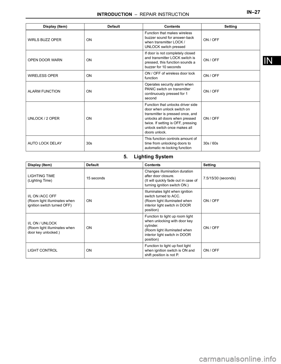
5. Lighting System
WIRLS BUZZ OPER ONFunction that makes wireless
buzzer sound for answer-back
when transmitter LOCK /
UNLOCK switch pressedON / OFF
OPEN DOOR WARN ONIf door is not completely closed
and transmitter LOCK switch is
pressed, this function sounds a
buzzer for 10 secondsON / OFF
WIRELESS OPER ONON / OFF of wireless door lock
functionON / OFF
ALARM FUNCTION ONOperates security alarm when
PANIC switch on transmitter
continuously pressed for 1
secondON / OFF
UNLOCK / 2 OPER ONFunction that unlocks driver side
door when unlock switch on
transmitter is pressed once, and
unlocks all doors when pressed
twice. If setting is OFF, pressing
unlock switch once makes all
doors unlock.ON / OFF
AUTO LOCK DELAY 30sThis function controls amount of
time from unlocking doors to
automatic re-locking function30s / 60s Display (Item) Default Contents Setting
Display (Item) Default Contents Setting
LIGHTING TIME
(Lighting Time)15 secondsChanges illumination duration
after door closure.
(It will quickly fade out in case of
turning ignition switch ON.)7.5/15/30 (seconds)
I/L ON /ACC OFF
(Room light illuminates when
ignition switch turned OFF)ONIlluminates light when ignition
switch turned to ACC.
(Room light illuminated when
interior light switch in DOOR
position)ON / OFF
I/L ON / UNLOCK
(Room light illuminates when
door key unlocked.)ONFunction to light up room light
when unlocking with door key
cylinder.
(Room light illuminated when
interior light switch in DOOR
position)ON / OFF
LIGHT CONTROL ONFunction to light up foot light
when ignition switch is ON and
shift position is not P.ON / OFF
Page 455 of 2000
DOOR LOCK – POWER DOOR LOCK CONTROL SYSTEMDL–3
DL
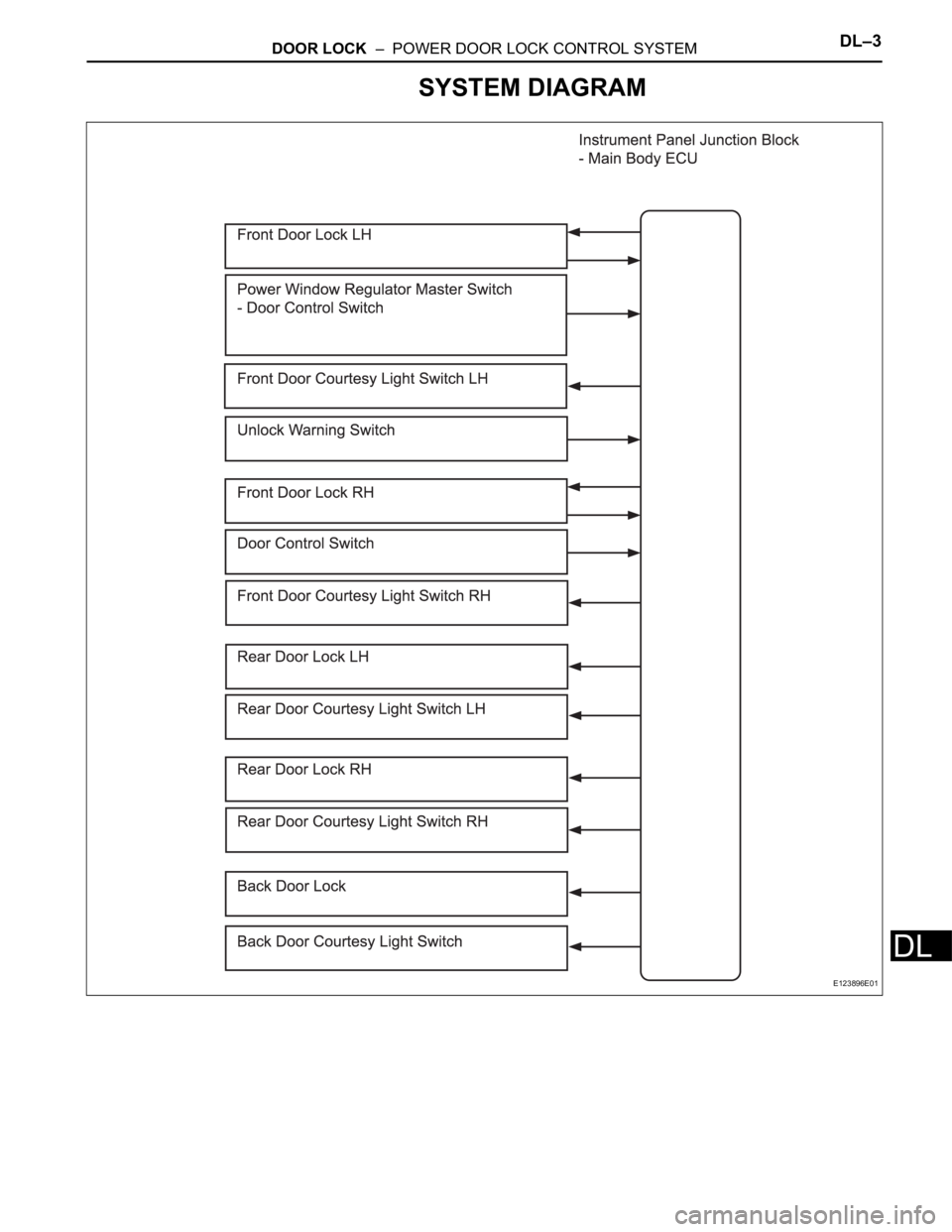
SYSTEM DIAGRAM
E123896E01
Page 456 of 2000
DL–4DOOR LOCK – POWER DOOR LOCK CONTROL SYSTEM
DL
SYSTEM DESCRIPTION
1. POWER DOOR LOCK SYSTEM DESCRIPTION
(a) The power door lock system locks / unlocks all
doors with a one-touch operation.
• The door control switch of the power window
regulator master switch or door control switch on
passenger side sends lock / unlock request
signals to the main body ECU. Then, the main
body ECU sends these requests to the lock
motors in each door to lock / unlock all the doors
simultaneously.
• Operating the driver side door lock using a key
sends lock / unlock request signals to the main
body ECU.
2. COMPONENTS
3. FUNCTIONS
This system is controlled by the main body ECU. The
main body ECU outputs signals to each door lock motor.
The door lock control system in the vehicle has the
following functions:
Components Function
Door control switch on power window regulator master switch Locks / unlocks all doors
Door control switch Locks / unlocks all doors
Door courtesy switch • Placed on each door.
• Detects door status (open or closed) and outputs data to main
body ECU.
• Turns on when door is open and off when door is closed.
Driver door lock • Built-in motor locks / unlocks door.
• Built-in door control switch (key-linked) detects door key
operation's door status (locked or unlocked) and outputs data to
main body ECU.
• Built-in position switch detects door status (locked or unlocked)
and outputs data to main body ECU. This switch turns off when
door is locked and on when door is unlocked.
• Front passenger door lock
• Rear door lock LH
• Rear door lock RH
• Back door lockBuilt-in motor locks / unlocks door.
Functions Outlines
Key-linked lock and unlock function Linked with key cylinder. Locks / unlocks all doors when lock / unlock
operation is possible.
Key lock-in prevention function When key is inserted in ignition key cylinder and door lock operation is
performed, all doors are unlocked.
Manual unlock prohibition function Performing door lock operation with transmitter or key disables unlock
operation by door control switch.
2-step unlock function Unlocks only driver door by turning key cylinder once and unlocks
other doors by turning it twice.
Page 457 of 2000
DL–108DOOR LOCK – DOOR CONTROL RECEIVER
DL
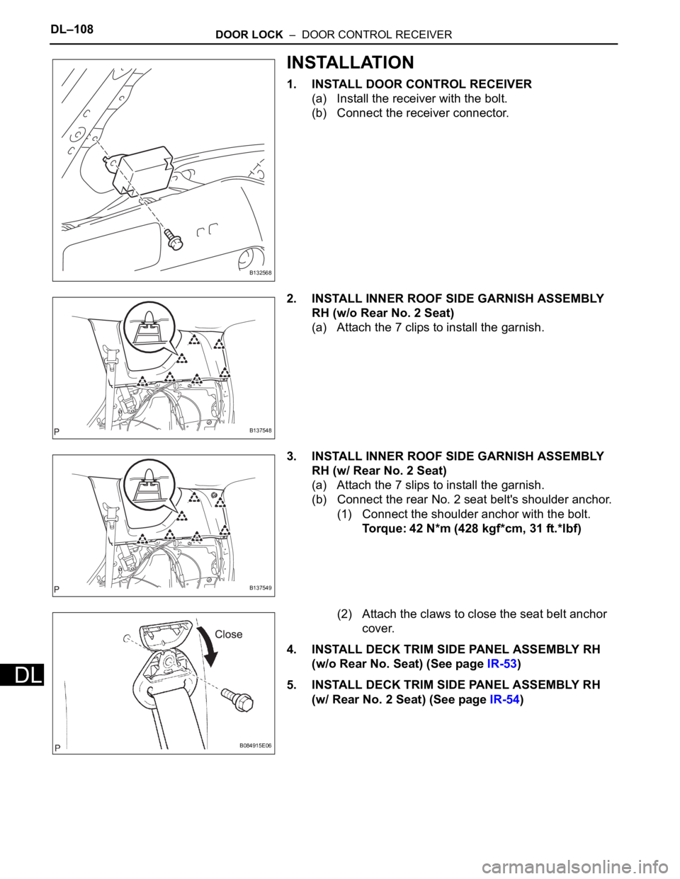
INSTALLATION
1. INSTALL DOOR CONTROL RECEIVER
(a) Install the receiver with the bolt.
(b) Connect the receiver connector.
2. INSTALL INNER ROOF SIDE GARNISH ASSEMBLY
RH (w/o Rear No. 2 Seat)
(a) Attach the 7 clips to install the garnish.
3. INSTALL INNER ROOF SIDE GARNISH ASSEMBLY
RH (w/ Rear No. 2 Seat)
(a) Attach the 7 slips to install the garnish.
(b) Connect the rear No. 2 seat belt's shoulder anchor.
(1) Connect the shoulder anchor with the bolt.
Torque: 42 N*m (428 kgf*cm, 31 ft.*lbf)
(2) Attach the claws to close the seat belt anchor
cover.
4. INSTALL DECK TRIM SIDE PANEL ASSEMBLY RH
(w/o Rear No. Seat) (See page IR-53)
5. INSTALL DECK TRIM SIDE PANEL ASSEMBLY RH
(w/ Rear No. 2 Seat) (See page IR-54)
B132568
B137548
B137549
B084915E06
Page 458 of 2000
DOOR LOCK – DOOR CONTROL RECEIVERDL–109
DL
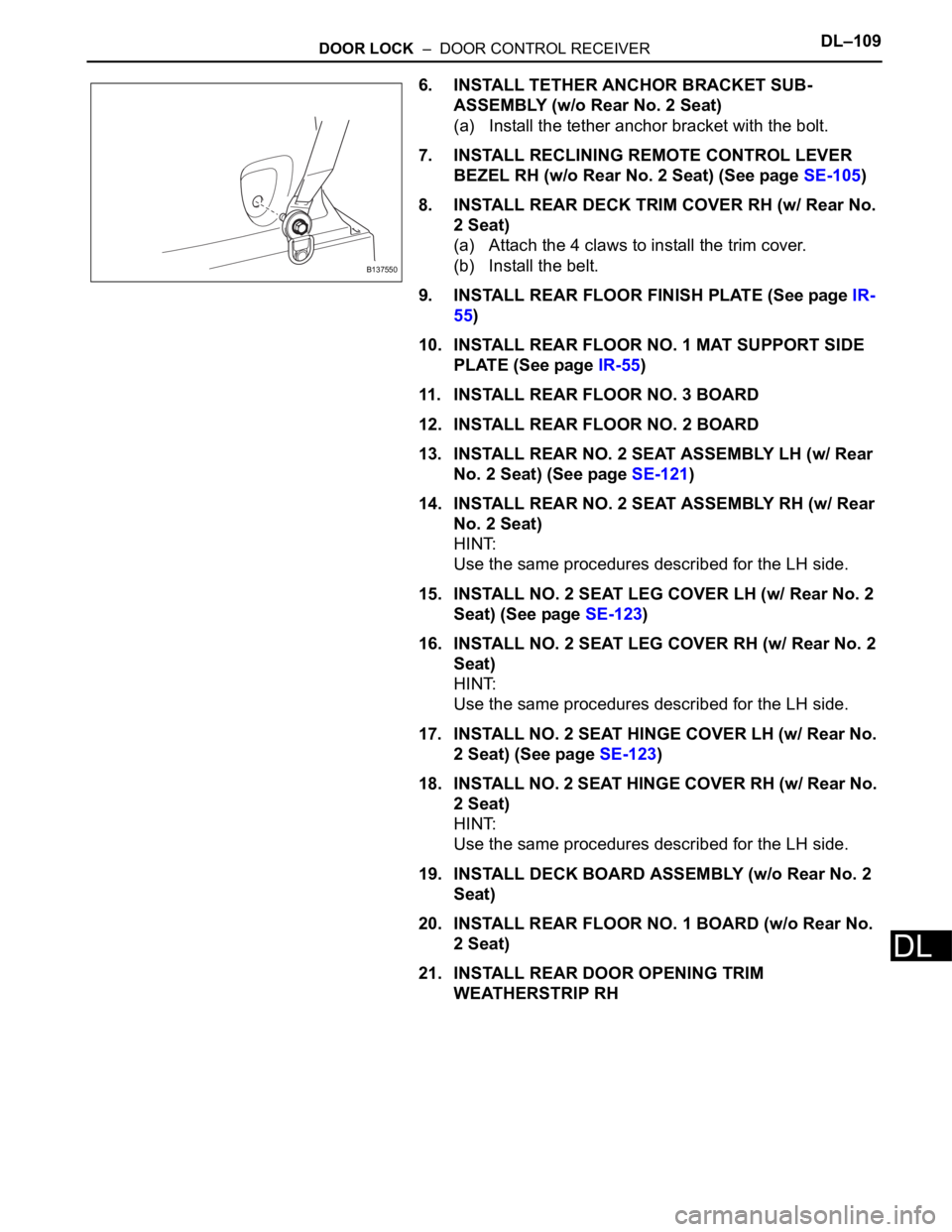
6. INSTALL TETHER ANCHOR BRACKET SUB-
ASSEMBLY (w/o Rear No. 2 Seat)
(a) Install the tether anchor bracket with the bolt.
7. INSTALL RECLINING REMOTE CONTROL LEVER
BEZEL RH (w/o Rear No. 2 Seat) (See page SE-105)
8. INSTALL REAR DECK TRIM COVER RH (w/ Rear No.
2 Seat)
(a) Attach the 4 claws to install the trim cover.
(b) Install the belt.
9. INSTALL REAR FLOOR FINISH PLATE (See page IR-
55)
10. INSTALL REAR FLOOR NO. 1 MAT SUPPORT SIDE
PLATE (See page IR-55)
11. INSTALL REAR FLOOR NO. 3 BOARD
12. INSTALL REAR FLOOR NO. 2 BOARD
13. INSTALL REAR NO. 2 SEAT ASSEMBLY LH (w/ Rear
No. 2 Seat) (See page SE-121)
14. INSTALL REAR NO. 2 SEAT ASSEMBLY RH (w/ Rear
No. 2 Seat)
HINT:
Use the same procedures described for the LH side.
15. INSTALL NO. 2 SEAT LEG COVER LH (w/ Rear No. 2
Seat) (See page SE-123)
16. INSTALL NO. 2 SEAT LEG COVER RH (w/ Rear No. 2
Seat)
HINT:
Use the same procedures described for the LH side.
17. INSTALL NO. 2 SEAT HINGE COVER LH (w/ Rear No.
2 Seat) (See page SE-123)
18. INSTALL NO. 2 SEAT HINGE COVER RH (w/ Rear No.
2 Seat)
HINT:
Use the same procedures described for the LH side.
19. INSTALL DECK BOARD ASSEMBLY (w/o Rear No. 2
Seat)
20. INSTALL REAR FLOOR NO. 1 BOARD (w/o Rear No.
2 Seat)
21. INSTALL REAR DOOR OPENING TRIM
WEATHERSTRIP RH
B137550
Page 459 of 2000
DL–110DOOR LOCK – DOOR CONTROL RECEIVER
DL
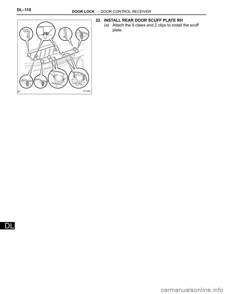
22. INSTALL REAR DOOR SCUFF PLATE RH
(a) Attach the 9 claws and 2 clips to install the scuff
plate.
B132566
Page 574 of 2000
SLIDING ROOF – SLIDING ROOF SYSTEMRF–3
RF
SYSTEM DESCRIPTION
1. GENERAL
This system has the following functions: manual slide
open and close; auto slide open and close; manual tilt up
and down; auto tilt up and down; jam protection; and key
off operation.
2. FUNCTION OF MAIN COMPONENT
3. SYSTEM OPERATION
The sliding roof has the following features.
Component Outline
Sliding roof drive gear sub-assembly (Sliding roof ECU) Sliding roof ECU controls sliding roof motor to rotate forward and
backward, which tilts or slides sliding roof glass
Overhead junction block Output of operation signals from built-in sliding roof switch to sliding
roof ECU are handled by overhead junction block
Function Outline
Manual slide open and close This function causes sliding roof to open (or close) when SLIDE
OPEN switch (or TILT UP switch) is pressed for a maximum of 0.3
seconds. Sliding roof stops as soon as switch is released.
Auto slide open and close This function causes sliding roof to be fully opened (or closed) when
SLIDE OPEN switch (or TILT UP switch) is pressed for a minimum of
0.3 seconds
Manual tilt up and down This function causes sliding roof to tilt up (or tilt down) when TILT UP
switch (or SLIDE OPEN switch) is pressed for a maximum of 0.3
seconds
Auto tilt up and down This function enables sliding roof to tilt up (or down) when TILT UP
switch (or SLIDE OPEN switch) is pressed for a minimum of 0.3
seconds.
Jam protection function The jam protection function automatically stops sliding roof, or stops
sliding roof and makes it open halfway (or fully tilts it upward) if a
foreign object gets jammed in sliding roof during auto close operation
(or auto tilt down operation).
Key off operation Key off operation function makes it possible to operate sliding roof for
approximately 45 seconds after ignition switch is turned off if front
doors are not opened