2006 TOYOTA RAV4 diagnostic menu
[x] Cancel search: diagnostic menuPage 475 of 2000

2AZ-FE ENGINE CONTROL SYSTEM – SFI SYSTEMES–21
ES
CHECKING MONITOR STATUS
The purpose of the monitor result (mode 06) is to allow
access to the results of on-board diagnostic monitoring tests
of specific components/systems that are not continuously
monitored. Examples are catalysts, evaporative emissions
(EVAP) and thermostats.
The monitor result allows the OBD II scan tool to display the
monitor status, test value, minimum test limit and maximum
test limit. These data are displayed after the vehicle has been
driven to run the monitor.
When the test value is not between the minimum and
maximum test limits, the ECM (PCM) interprets this as a
malfunction. If the test value is on the borderline of the test
limits, the component is likely to malfunction in the near
future.
Perform the following instruction to view the monitor status.
Although this instruction refers to the Lexus/Toyota diagnostic
tester, it can be checked using a generic OBD II scan tool.
Refer to your scan tool operator's manual for specific
procedural information.
1. PERFORM MONITOR DRIVE PATTERN
(a) Connect the intelligent tester to the DLC3.
(b) Turn the ignition switch and the tester ON.
(c) Clear the DTCs (see page ES-35).
(d) Run the vehicle in accordance with the applicable
drive pattern described in READINESS MONITOR
DRIVE PATTERN (see page ES-19). Do not turn the
ignition switch OFF.
NOTE:
The test results will be lost if the ignition
switch is turned OFF.
2. ACCESS MONITOR RESULT
(a) Select the following items from the intelligent tester
menus: DIAGNOSIS, ENHANCED OBD II,
MONITOR INFO and MONITOR RESULT. The
monitor status appears after the component name.
• INCMP: The component has not been monitored
yet.
• PASS: The component is functioning normally.
• FAIL: The component is malfunctioning.
(b) Confirm that the component is either PASS or FAIL.
(c) Select the component and press ENTER. The
accuracy test value appears if the monitor status is
either PASS or FAIL.
3. CHECK COMPONENT STATUS
(a) Compare the test value with the minimum test limit
(MIN LIMIT) and maximum test limit (MAX LIMIT).
Page 478 of 2000

ES–242AZ-FE ENGINE CONTROL SYSTEM – SFI SYSTEM
ES
READINESS MONITOR DRIVE
PAT T E R N
1. PURPOSE OF READINESS TESTS
• The On-Board Diagnostic (OBD II) system is designed to
monitor the performance of emission related components,
and indicate any detected abnormalities with DTC
(Diagnostic Trouble Codes). Since various components
need to be monitored during different driving conditions,
the OBD II system is designed to run separate monitoring
programs called Readiness Monitors.
• The intelligent tester's software must be version 9.0 or
newer to view the Readiness Monitor Status. To view the
status, select the following menu items: DIAGNOSIS /
ENHANCED OBD II / MONITOR INFO / MONITOR
STATUS.
• When the Readiness Monitor status reads COMPL
(complete), the necessary conditions have been met for
running the performance tests for that Readiness Monitor.
• A generic OBD II scan tool can also be used to view the
Readiness Monitor status.
HINT:
Many state Inspection and Maintenance (I/M) programs
require a vehicle's Readiness Monitor status to show COMPL
before beginning emission tests.
The Readiness Monitor will be reset to INCMPL (incomplete)
if:
• The ECM has lost battery power or blown a fuse.
• DTCs have been cleared.
• The conditions for running the Readiness Monitor have not
been met.
If the Readiness Monitor status shows INCMPL, follow the
appropriate Readiness Monitor Drive Pattern to change the
status to COMPL.
CAUTION:
Strictly observe posted speed limits, traffic laws, and
road conditions when performing these drive patterns.
NOTICE:
These drive patterns represent the fastest method of
satisfying all conditions necessary to achieve complete
status for each specific Readiness Monitor.
In the event of a drive pattern being interrupted (possibly
due to factors such as traffic conditions), the drive
pattern can be resumed. In most cases, the Readiness
Monitor will still achieve complete status upon
completion of the drive pattern.
To ensure completion of the Readiness Monitors, avoid
sudden changes in vehicle load and speed (driving up
and down hills and/or sudden acceleration).
Page 547 of 2000

2GR-FE ENGINE CONTROL SYSTEM – SFI SYSTEMES–23
ES
CHECKING MONITOR STATUS
The purpose of the monitor result (mode 06) is to allow
access to the results of on-board diagnostic monitoring tests
of specific components/systems that are not continuously
monitored. Examples are catalysts, evaporative emissions
(EVAP) and thermostats.
The monitor result allows the OBD II scan tool to display the
monitor status, test value, minimum test limit and maximum
test limit. These data are displayed after the vehicle has been
driven to run the monitor.
When the test value is not between the minimum and
maximum test limits, the ECM (PCM) interprets this as a
malfunction. If the test value is on the borderline of the test
limits, the component is likely to malfunction in the near
future.
Perform the following procedures to view the monitor status.
Although these procedures refer to the Lexus/Toyota
diagnostic tester, the monitor status can be checked using a
generic OBD II scan tool. Refer to your scan tool operator's
manual for specific procedural information.
1. PERFORM MONITOR DRIVE PATTERN
(a) Connect the intelligent tester to the DLC3.
(b) Turn the ignition switch and the tester ON.
(c) Clear the DTCs (see page ES-39).
(d) Run the vehicle in accordance with the applicable
drive pattern described in READINESS MONITOR
DRIVE PATTERN (see page ES-22). Do not turn the
ignition switch OFF.
NOTE:
The test results will be lost if the ignition
switch is turned OFF.
2. ACCESS MONITOR RESULT
(a) Select the following items from the intelligent tester
menus: DIAGNOSIS, ENHANCED OBD II,
MONITOR INFO and MONITOR RESULT. The
monitor status appears after the component name.
• INCMP: The component has not been monitored
yet.
• PASS: The component is functioning normally.
• FAIL: The component is malfunctioning.
(b) Confirm that the component is either PASS or FAIL.
(c) Select the component and press ENTER. The
accuracy test value appears if the monitor status is
either PASS or FAIL.
3. CHECK COMPONENT STATUS
(a) Compare the test value with the minimum test limit
(MIN LIMIT) and maximum test limit (MAX LIMIT).
Page 551 of 2000

2GR-FE ENGINE CONTROL SYSTEM – SFI SYSTEMES–27
ES
READINESS MONITOR DRIVE
PAT T E R N
1. PURPOSE OF READINESS TESTS
• The On-Board Diagnostic (OBD II) system is designed to
monitor the performance of emission related components,
and indicate any detected abnormalities with DTC
(Diagnostic Trouble Codes). Since various components
need to be monitored during different driving conditions,
the OBD II system is designed to run separate monitoring
programs called Readiness Monitors.
• The intelligent tester's software must be version 9.0 or
newer to view the Readiness Monitor Status. To view the
status, select the following menu items: DIAGNOSIS /
ENHANCED OBD II / MONITOR INFO / MONITOR
STATUS.
• When the Readiness Monitor status reads COMPL
(complete), the necessary conditions have been met for
running the performance tests for that Readiness Monitor.
• A generic OBD II scan tool can also be used to view the
Readiness Monitor status.
HINT:
Many state Inspection and Maintenance (I/M) programs
require a vehicle's Readiness Monitor status to show COMPL
before beginning emission tests.
The Readiness Monitor will be reset to INCMPL (incomplete)
if:
• The ECM has lost battery power or blown a fuse.
• DTCs have been cleared.
• The conditions for running the Readiness Monitor have not
been met.
If the Readiness Monitor status shows INCMPL, follow the
appropriate Readiness Monitor Drive Pattern to change the
status to COMPL.
CAUTION:
Strictly observe posted speed limits, traffic laws, and
road conditions when performing these drive patterns.
NOTICE:
These drive patterns represent the fastest method of
satisfying all conditions necessary to achieve complete
status for each specific Readiness Monitor.
In the event of a drive pattern being interrupted (possibly
due to factors such as traffic conditions), the drive
pattern can be resumed. In most cases, the Readiness
Monitor will still achieve complete status upon
completion of the drive pattern.
To ensure completion of the Readiness Monitors, avoid
sudden changes in vehicle load and speed (driving up
and down hills and/or sudden acceleration).
Page 969 of 2000

U140F AUTOMATIC TRANSAXLE – AUTOMATIC TRANSAXLE SYSTEMAX–35
AX
If communication is normal when the tester is connected to
another vehicle, inspect the DLC3 on the original vehicle.
If communication is still not possible when the tester is
connected to another vehicle, the problem is probably in the
tester itself. Consult the Service Department listed in the
tester's instruction manual.
6. CHECK MIL
(a) Check that the MIL illuminates when turning the
ignition switch ON.
If the MIL does not illuminate, there is a problem in
the MIL circuit (see page ES-386).
(b) When the engine is started, the MIL should turn off.
7. ALL READINESS
(a) For this vehicle, using the intelligent tester allows
readiness codes corresponding to all DTCs to be
read. When the diagnosis (normal or
malfunctioning) has been completed, readiness
codes are set. Enter the following menus:
ENHANCED OBD II / MONITOR STATUS.
DTC CHECK / CLEAR
1. CHECK DTC
(a) DTCs which are stored in the ECM can be displayed
with the intelligent tester.
The intelligent tester can display pending DTCs and
current DTCs. Some DTCs are not stored unless a
malfunction is detected in consecutive driving
cycles. When a malfunction is detected in only one
driving cycle, it is stored as a pending DTC.
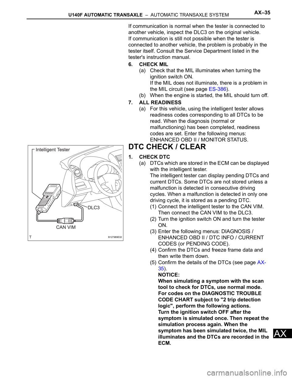
(1) Connect the intelligent tester to the CAN VIM.
Then connect the CAN VIM to the DLC3.
(2) Turn the ignition switch ON and turn the tester
ON.
(3) Enter the following menus: DIAGNOSIS /
ENHANCED OBD II / DTC INFO / CURRENT
CODES (or PENDING CODE).
(4) Confirm the DTCs and freeze frame data and
then write them down.
(5) Confirm the details of the DTCs (see page AX-
35).
NOTICE:
When simulating a symptom with the scan
tool to check for DTCs, use normal mode.
For codes on the DIAGNOSTIC TROUBLE
CODE CHART subject to "2 trip detection
logic", perform the following actions.
Turn the ignition switch OFF after the
symptom is simulated once. Then repeat the
simulation process again. When the
symptom has been simulated twice, the MIL
illuminates and the DTCs are recorded in the
ECM.
B127989E02
Page 1052 of 2000

AX–36U151E AUTOMATIC TRANSAXLE – AUTOMATIC TRANSAXLE SYSTEM
AX
HINT:
Connect the cable of the intelligent tester to the DLC3, turn
the ignition switch ON and attempt to use the tester. If the
screen displays UNABLE TO CONNECT TO VEHICLE, a
problem exists in the vehicle side or the tester side.
If communication is normal when the tester is connected to
another vehicle, inspect the DLC3 on the original vehicle.
If communication is still not possible when the tester is
connected to another vehicle, the problem is probably in the
tester itself. Consult the Service Department listed in the
tester's instruction manual.
6. CHECK MIL
(a) Check that the MIL illuminates when turning the
ignition switch ON.
If the MIL does not illuminate, there is a problem in
the MIL circuit (see page ES-430).
(b) When the engine is started, the MIL should turn off.
7. ALL READINESS
(a) For this vehicle, using the intelligent tester allows
readiness codes corresponding to all DTCs to be
read. When the diagnosis (normal or
malfunctioning) has been completed, readiness
codes are set. Enter the following menus:
ENHANCED OBD II / MONITOR STATUS.
DTC CHECK / CLEAR
1. CHECK DTC
(a) DTCs which are stored in the ECM can be displayed
with the intelligent tester.
The intelligent tester can display pending DTCs and
current DTCs. Some DTCs are not stored unless a
malfunction is detected in consecutive driving
cycles. When a malfunction is detected in only one
driving cycle, it is stored as a pending DTC.
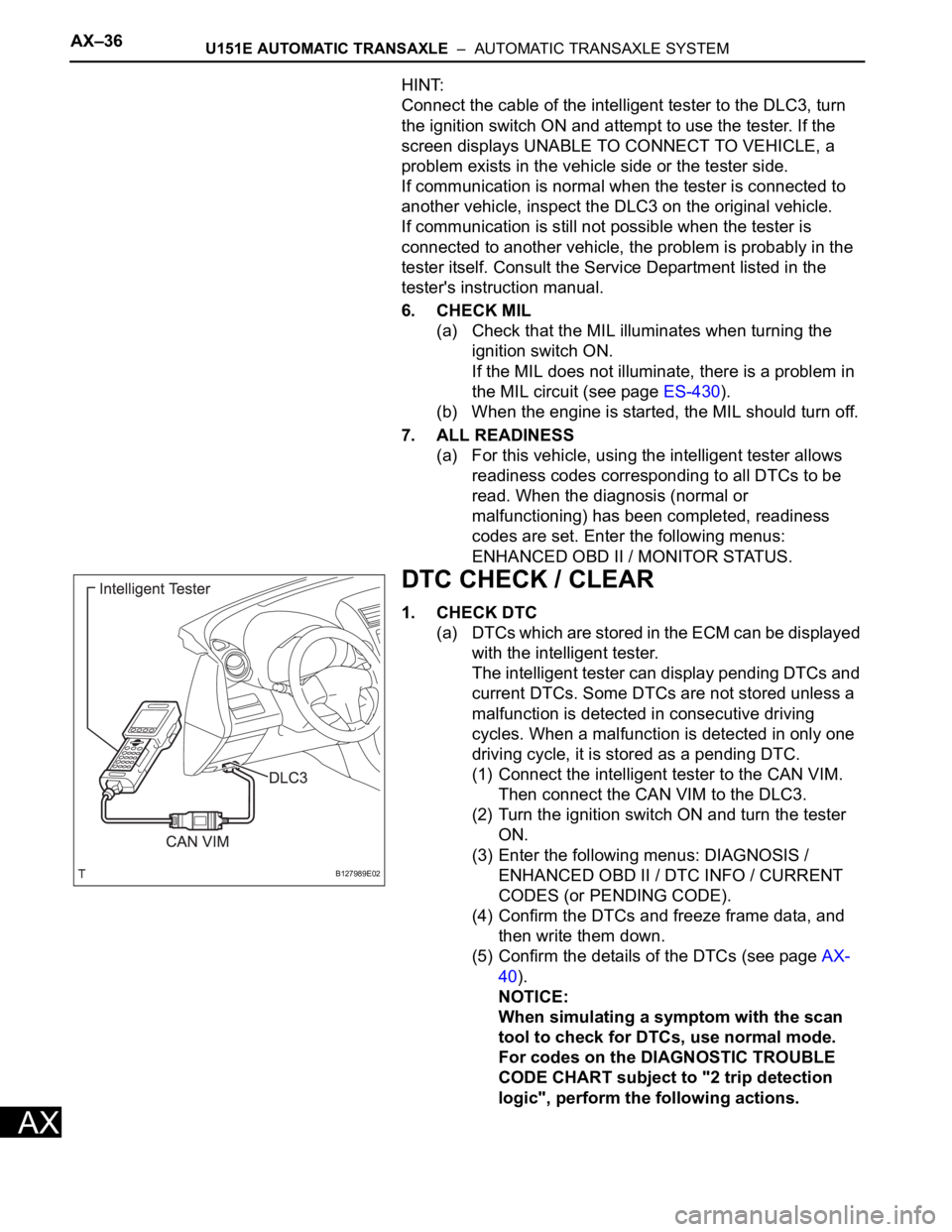
(1) Connect the intelligent tester to the CAN VIM.
Then connect the CAN VIM to the DLC3.
(2) Turn the ignition switch ON and turn the tester
ON.
(3) Enter the following menus: DIAGNOSIS /
ENHANCED OBD II / DTC INFO / CURRENT
CODES (or PENDING CODE).
(4) Confirm the DTCs and freeze frame data, and
then write them down.
(5) Confirm the details of the DTCs (see page AX-
40).
NOTICE:
When simulating a symptom with the scan
tool to check for DTCs, use normal mode.
For codes on the DIAGNOSTIC TROUBLE
CODE CHART subject to "2 trip detection
logic", perform the following actions.
B127989E02
Page 1155 of 2000

AX–36U151F AUTOMATIC TRANSAXLE – AUTOMATIC TRANSAXLE SYSTEM
AX
HINT:
Connect the cable of the intelligent tester to the DLC3, turn
the ignition switch ON and attempt to use the tester. If the
screen displays UNABLE TO CONNECT TO VEHICLE, a
problem exists in the vehicle side or the tester side.
If communication is normal when the tester is connected to
another vehicle, inspect the DLC3 on the original vehicle.
If communication is still not possible when the tester is
connected to another vehicle, the problem is probably in the
tester itself. Consult the Service Department listed in the
tester's instruction manual.
6. CHECK MIL
(a) Check that the MIL illuminates when turning the
ignition switch ON.
If the MIL does not illuminate, there is a problem in
the MIL circuit (see page ES-430).
(b) When the engine is started, the MIL should turn off.
7. ALL READINESS
(a) For this vehicle, using the intelligent tester allows
readiness codes corresponding to all DTCs to be
read. When the diagnosis (normal or
malfunctioning) has been completed, readiness
codes are set. Enter the following menus:
ENHANCED OBD II / MONITOR STATUS.
DTC CHECK / CLEAR
1. CHECK DTC
(a) DTCs which are stored in the ECM can be displayed
with the intelligent tester.
The intelligent tester can display pending DTCs and
current DTCs. Some DTCs are not stored unless a
malfunction is detected in consecutive driving
cycles. When a malfunction is detected in only one
driving cycle, it is stored as a pending DTC.
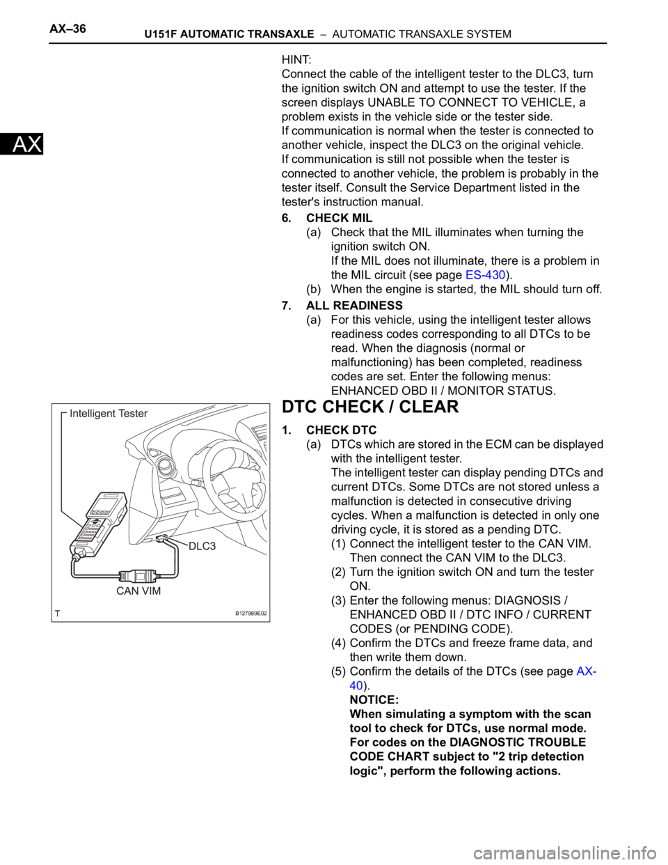
(1) Connect the intelligent tester to the CAN VIM.
Then connect the CAN VIM to the DLC3.
(2) Turn the ignition switch ON and turn the tester
ON.
(3) Enter the following menus: DIAGNOSIS /
ENHANCED OBD II / DTC INFO / CURRENT
CODES (or PENDING CODE).
(4) Confirm the DTCs and freeze frame data, and
then write them down.
(5) Confirm the details of the DTCs (see page AX-
40).
NOTICE:
When simulating a symptom with the scan
tool to check for DTCs, use normal mode.
For codes on the DIAGNOSTIC TROUBLE
CODE CHART subject to "2 trip detection
logic", perform the following actions.
B127989E02
Page 1259 of 2000

U241E AUTOMATIC TRANSAXLE – AUTOMATIC TRANSAXLE SYSTEMAX–35
AX
If communication is normal when the tester is connected to
another vehicle, inspect the DLC3 on the original vehicle.
If communication is still not possible when the tester is
connected to another vehicle, the problem is probably in the
tester itself. Consult the Service Department listed in the
tester's instruction manual.
6. CHECK MIL
(a) Check that the MIL illuminates when turning the
ignition switch ON.
If the MIL does not illuminate, there is a problem in
the MIL circuit (see page ES-386).
(b) When the engine is started, the MIL should turn off.
7. ALL READINESS
(a) For this vehicle, using the intelligent tester allows
readiness codes corresponding to all DTCs to be
read. When the diagnosis (normal or
malfunctioning) has been completed, readiness
codes are set. Enter the following menus:
ENHANCED OBD II / MONITOR STATUS.
DTC CHECK / CLEAR
1. CHECK DTC
(a) DTCs which are stored in the ECM can be displayed
with the intelligent tester.
The intelligent tester can display pending DTCs and
current DTCs. Some DTCs are not stored unless a
malfunction is detected in consecutive driving
cycles. When a malfunction is detected in only one
driving cycle, it is stored as a pending DTC.
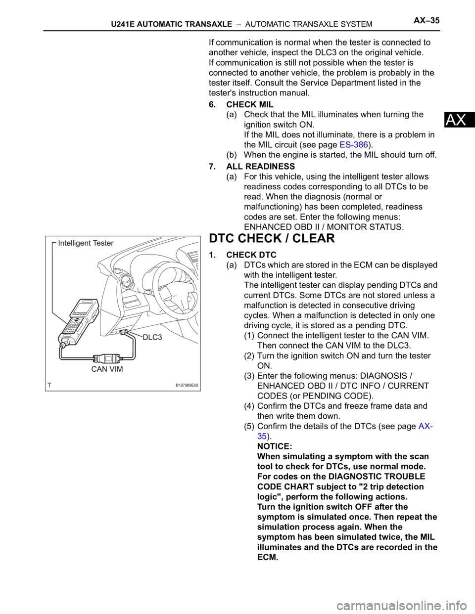
(1) Connect the intelligent tester to the CAN VIM.
Then connect the CAN VIM to the DLC3.
(2) Turn the ignition switch ON and turn the tester
ON.
(3) Enter the following menus: DIAGNOSIS /
ENHANCED OBD II / DTC INFO / CURRENT
CODES (or PENDING CODE).
(4) Confirm the DTCs and freeze frame data and
then write them down.
(5) Confirm the details of the DTCs (see page AX-
35).
NOTICE:
When simulating a symptom with the scan
tool to check for DTCs, use normal mode.
For codes on the DIAGNOSTIC TROUBLE
CODE CHART subject to "2 trip detection
logic", perform the following actions.
Turn the ignition switch OFF after the
symptom is simulated once. Then repeat the
simulation process again. When the
symptom has been simulated twice, the MIL
illuminates and the DTCs are recorded in the
ECM.
B127989E02