Page 677 of 2000

2GR-FE ENGINE MECHANICAL – ENGINE ASSEMBLYEM–31
EM
INSTALLATION
1. INSTALL ENGINE COOLANT TEMPERATURE
SENSOR
(a) Using a 19 mm deep socket wrench, install the
sensor and a new gasket.
Torque: 20 N*m (204 kgf*cm, 14 ft.*lbf)
2. INSTALL KNOCK SENSOR (See page ES-459)
3. INSTALL ENGINE OIL PRESSURE SWITCH
ASSEMBLY
(a) Clean the threads of the oil pressure switch. Apply
adhesive to 2 or 3 threads of the oil pressure switch.
Adhesive:
Toyota Genuine Adhesive 1344, Three Bond
1344 or Equivalent
(b) Using a 24 mm deep socket wrench, install the oil
pressure switch.
Torque: 21 N*m (214 kgf*cm, 15 ft.*lbf)
4. INSTALL NO. 1 FRONT ENGINE MOUNTING
BRACKET LH
(a) Install the mounting bracket with the 6 bolts.
Torque: 54 N*m (551 kgf*cm, 40 ft.*lbf)
5. INSTALL WATER PUMP PULLEY (See page CO-14)
6. INSTALL NO. 2 IDLER PULLEY SUB-ASSEMBLY
(a) Install the idler pulley and cover plate with the bolt.
Torque: 43 N*m (438 kgf*cm, 32 ft.*lbf)
7. INSTALL NO. 2 TIMING GEAR COVER
(a) Install the gear cover with the 2 bolts.
Torque: 6.0 N*m (61 kgf*cm, 53 in.*lbf)
8. INSTALL V-RIBBED BELT TENSIONER ASSEMBLY
(a) Temporarily install the V-ribbed belt tensioner with
the 5 bolts.
(b) Install the V-ribbed belt tensioner by tightening the
bolt 1 and bolt 2 in the order shown in the
illustration.
Torque: 43 N*m (438 kgf*cm, 32 ft.*lbf)
(c) Tighten the other bolts.
Torque: 43 N*m (438 kgf*cm, 32 ft.*lbf)
Each bolt length is as follows:
A129648
A129647
A129646
A139522
A139138E01
A 70 mm (2.76 in.)
Page 763 of 2000
EM–1262GR-FE ENGINE MECHANICAL – ENGINE UNIT
EM
(d) Remove the lock pin of the chain tensioner. Check
that each timing mark is aligned with the crankshaft
at the TDC / compression.
(e) Remove the pulley set bolt.
37. INSTALL TIMING CHAIN COVER SUB-ASSEMBLY (w/
Oil Pump) (See page LU-17)
38. INSTALL WATER PUMP ASSEMBLY (See page CO-
13)
39. INSTALL ENGINE REAR OIL SEAL RETAINER
(a) Apply seal packing in a continuous line as shown in
the illustration.
Seal packing:
Toyota Genuine Seal Packing Block, Three
Bond 1207B or Equivalent
Standard seal diameter:
2.0 to 3.0 mm (0.079 to 0.118 in.)
NOTICE:
• Remove any oil from the contact surface.
• Install the crankcase within 3 minutes after
applying seal packing.
• Do not start the engine for at least 2 hours
after the installation.
A132117E01
A131897E03
Page 843 of 2000

2AZ-FE COOLING – WATER PUMPCO–13
CO
INSTALLATION
1. INSTALL WATER PUMP ASSEMBLY
(a) Remove any old seal packing material from the
contact surface.
(b) Apply a continuous line of seal packing as shown in
the illustration.
Seal packing:
Toyota Genuine Seal Parking Black, Three
Bond 1207B or equivalent
Standard seal diameter:
2.2 to 2.5 mm (0.09 to 0.10 in.)
NOTICE:
• Remove any oil from the contact surface.
• The parts must be set within 3 minutes after
applying seal packing. Otherwise, the
material must be removed and reapplied.
(c) Install the water pump and clamp bracket with the 4
bolts and 2 nuts.
Torque: 9.0 N*m (92 kgf*cm, 80 in.*lbf)
(d) Install the wire of the crankshaft position sensor
onto the clamp bracket.
(e) Install the clamp of the crankshaft position sensor
onto the water pump.
2. INSTALL WATER PUMP PULLEY
(a) Using SST, install the water pump pulley with the 4
bolts.
SST 09960-10010 (09962-01000, 09963-00700)
Torque: 26 N*m (265 kgf*cm, 19 ft.*lbf)
3. INSTALL GENERATOR ASSEMBLY (See page CH-15)
4. INSTALL FAN AND GENERATOR V BELT (See page
EM-7)
5. INSTALL FRONT SUSPENSION MEMBER
REINFORCEMENT RH (See page EM-7)
6. CONNECT CABLE TO NEGATIVE BATTERY
TERMINAL
7. ADD ENGINE COOLANT (See page CO-6)
8. CHECK FOR ENGINE COOLANT LEAKS (See page
CO-1)
9. INSTALL RADIATOR SUPPORT OPENING COVER
10. INSTALL FRONT FENDER APRON RH
11. INSTALL NO. 1 ENGINE UNDER COVER
A094495E03
A098715E02
Page 856 of 2000
2GR-FE COOLING – WATER PUMPCO–13
CO
6. REMOVE NO. 2 IDLER PULLEY SUB-ASSEMBLY
(a) Remove the bolt, No. 2 idler pulley cover plate and
No. 2 idler pulley.
7. REMOVE V-RIBBED BELT TENSIONER ASSEMBLY
(a) Remove the 5 bolts and V-ribbed belt tensioner
assembly.
8. REMOVE WATER PUMP ASSEMBLY
(a) Remove the 16 bolts, water pump and water pump
gasket.
INSPECTION
1. INSPECT WATER PUMP ASSEMBLY
(a) Visually check the drain hole for coolant leakage.
If leakage is found, replace the water pump
assembly.
(b) Turn the pulley, and then check that the water pump
bearing moves smoothly without making a clicking
noise.
If it does not move smoothly, replace the water
pump assembly.
INSTALLATION
1. INSTALL WATER PUMP ASSEMBLY
(a) Install a new water pump gasket and the water
pump with the 16 bolts.
Torque: 21 N*m (214 kgf*cm, 15 ft.*lbf) for bolt A
9.1 N*m (93 kgf*cm, 81 in.*lbf) for bolt B
and C
A132445
A138913
A132448
A096655E01
A132448E01
Page 857 of 2000

CO–142GR-FE COOLING – WATER PUMP
CO
NOTICE:
• Be sure to replace the 2 C bolts with new
ones or reuse them after applying adhesive.
Adhesive:
Toyota Genuine Adhesive 1344, Three Bond
1344 or Equivalent
• Make sure that there is no oil on the threads
of the A bolts.
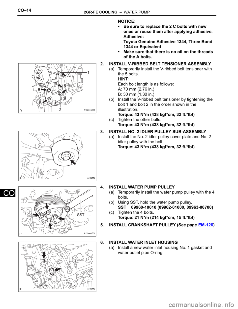
2. INSTALL V-RIBBED BELT TENSIONER ASSEMBLY
(a) Temporarily install the V-ribbed belt tensioner with
the 5 bolts.
HINT:
Each bolt length is as follows:
A: 70 mm (2.76 in.)
B: 30 mm (1.30 in.)
(b) Install the V-ribbed belt tensioner by tightening the
bolt 1 and bolt 2 in the order shown in the
illustration.
Torque: 43 N*m (438 kgf*cm, 32 ft.*lbf)
(c) Tighten the other bolts.
Torque: 43 N*m (438 kgf*cm, 32 ft.*lbf)
3. INSTALL NO. 2 IDLER PULLEY SUB-ASSEMBLY
(a) Install the No. 2 idler pulley cover plate and No. 2
idler pulley with the bolt.
Torque: 43 N*m (438 kgf*cm, 32 ft.*lbf)
4. INSTALL WATER PUMP PULLEY
(a) Temporarily install the water pump pulley with the 4
bolts.
(b) Using SST, hold the water pump pulley.
SST 09960-10010 (09962-01000, 09963-00700)
(c) Tighten the 4 bolts.
Torque: 21 N*m (214 kgf*cm, 15 ft.*lbf)
5. INSTALL CRANKSHAFT PULLEY (See page EM-126)
6. INSTALL WATER INLET HOUSING
(a) Install a new water inlet housing No. 1 gasket and
water outlet pipe O-ring.
A138913E01
A132445
A132444E01
A132443
Page 858 of 2000
2GR-FE COOLING – WATER PUMPCO–15
CO
(b) Install the water inlet with the 2 bolts and nut.
Torque: 10 N*m (102 kgf*cm, 7 ft.*lbf)
NOTICE:
Be careful not to allow the O-ring to get caught
between the parts.
(c) Connect the water hose.
7. INSTALL FRONT NO. 1 ENGINE MOUNTING
BRACKET LH
(a) Install the front No. 1 engine mounting bracket LH
with the 6 bolts.
Torque: 54 N*m (551 kgf*cm, 40 ft.*lbf)
NOTICE:
• Install the water inlet and mounting bracket
within 15 minutes after installing the chain
cover.
• Do not start the engine for at least 2 hours
after installation.
8. INSTALL ENGINE ASSEMBLY
(a) Install the engine (see page EM-31).
A132442
A136828E01
Page 882 of 2000

LU–222GR-FE LUBRICATION – OIL PUMP
LU
(f) Tighten the bolts in this order: Area 1, Area 2, Area
3, Area 4.
Torque: 21 N*m (214 kgf*cm, 15 ft.*lbf) for Area
1, 2 bolt
21 N*m (214 kgf*cm, 15 ft.*lbf) for Area 3
bolt, nut
43 N*m (438 kgf*cm, 32 ft.*lbf) for Area 4
bolt A
21 N*m (214 kgf*cm, 15 ft.*lbf) for Area 4
except bolt A
2. INSTALL CRANKSHAFT PULLEY (See page EM-126)
3. INSTALL CYLINDER HEAD COVER SUB-ASSEMBLY
(for Bank 2) (See page EM-127)
4. INSTALL NO. 1 OIL PIPE (See page EM-128)
5. INSTALL CYLINDER HEAD COVER SUB-ASSEMBLY
(for Bank 1) (See page EM-127)
6. INSTALL OIL PIPE (See page EM-127)
7. INSTALL WATER INLET HOUSING (See page CO-14)
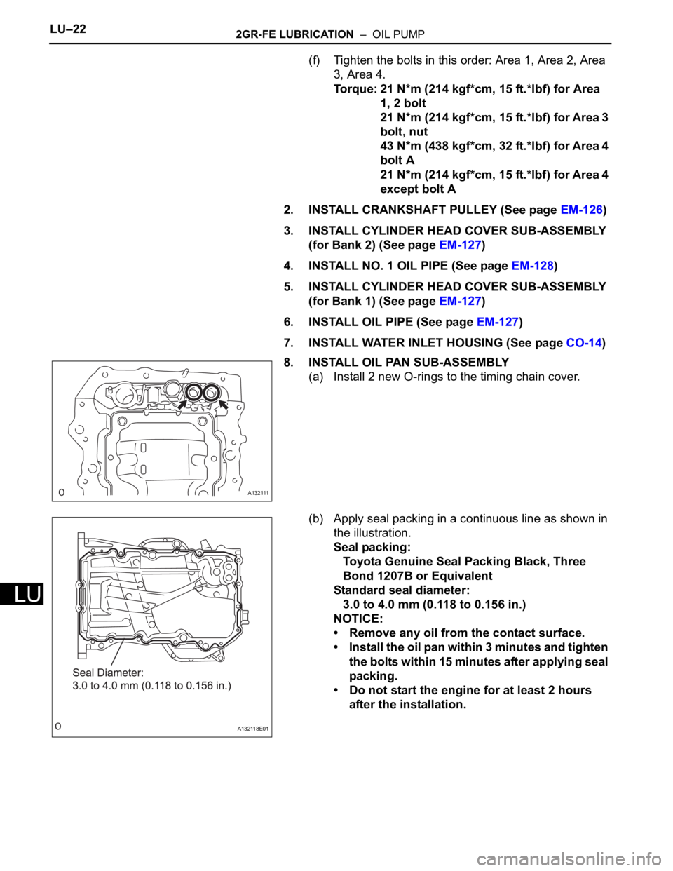
8. INSTALL OIL PAN SUB-ASSEMBLY
(a) Install 2 new O-rings to the timing chain cover.
(b) Apply seal packing in a continuous line as shown in
the illustration.
Seal packing:
Toyota Genuine Seal Packing Black, Three
Bond 1207B or Equivalent
Standard seal diameter:
3.0 to 4.0 mm (0.118 to 0.156 in.)
NOTICE:
• Remove any oil from the contact surface.
• Install the oil pan within 3 minutes and tighten
the bolts within 15 minutes after applying seal
packing.
• Do not start the engine for at least 2 hours
after the installation.
A132111
A132118E01
Page 1377 of 2000
DRIVE SHAFT – FRONT DRIVE SHAFT ASSEMBLY (for 2WD)DS–21
DS
(a) Install a new boot clamp to the outboard joint boot
and temporarily bend the lever.
NOTICE:
When temporarily bending the lever, make sure
not to deform the band and lever.
(b) Using water pump pliers, temporarily lock the boot
clamp by clamping it down until a "click" sound is
heard.
(c) Using a plastic-faced hammer, fix the buckle into
place by tapping it. At the same time, use the
plastic-faced hammer to adjust the lift of the lever so
that the gaps between the buckle flange and lever
end flange become even.
NOTICE:
Do not strike the drive shaft forcefully with the
plastic-faced hammer.
10. INSTALL FRONT AXLE OUTBOARD JOINT BOOT RH
CLAMP
HINT:
Use the same procedures described for the LH side.
C129511
C129512