Page 23 of 2000
ENGINE - 2AZ-FE ENGINE
01NEG45Y
RegulatorB
M
IG
RLO
L
Ignition Switch
To Discharge
Wa r n i n g L i g h t
Generator
ECM
281EG13
281EG12
Coil SpringPulley
Helical Coil Type One-way Clutch EG-26
Wiring Diagram
2. Generator Pulley
A helical coil type one-way clutch is used on the generator pulley in order to reduce the load that acts on
the auxiliary equipment belt.
The pulley mounting nut and the generator pulley have been integrated to achieve a compact construction.
Page 49 of 2000

ENGINE - 2AZ-FE ENGINE
01NEG09Y
01NEG10Y
Air
Conditioning
ECU
Engine Coolant
Temperature SensorFANL
ECM
FA N HCooling Fan
Relay No.3
Cooling Fan
Motor No.2
Cooling Fan
Relay No.1
Cooling Fan
Motor No.1
Low Speed (Series Connection)
High Speed (Parallel Connection) Air
Conditioning
ECU
Engine Coolant
Temperature SensorFA N L
ECM
FA N HCooling Fan
Relay No.3
Cooling Fan
Motor No.2
Cooling Fan
Relay No.1
Cooling Fan
Relay No.2
Cooling Fan
Motor No.1 : CAN
Cooling Fan
Relay No.2
EG-52
8. Cooling Fan Control
On the models with air conditioning, the ECM controls the operation of the cooling fan in two speeds (Low
and High) based on the engine coolant temperature sensor signal and the air conditioning ECU signal. This
control is accomplished by operating the 2 fan motors in 2 stages through low speed (series connection) and
high speed (parallel connection).
Wiring Diagram
Cooling Fan Operation
Air Conditioning ConditionEngine Coolant Temperature C (F)
A / C CompressorRefrigerant Pressure94 (201.2) or lower95.5 (203.9) or higher
OFF1.2 MPa (12.5 kgf / cm2, 178 psi) or lowerOFFHigh
ON1.2 MPa (12.5 kgf / cm2, 178 psi) or lowerLowHighON1.2 MPa (12.5 kgf / cm2, 178 psi) or higherHighHigh
Page 94 of 2000
ENGINE - 2GR-FE ENGINE
01NEG63Y
01MEG36Y
Generator
Stator
RotorRegulator
EB
IG
M
RLOL
Ignition Switch
ECM
Towing Package Models and Models with RSES
Other Models Generator
Rectifier
Stator
Rotor
ERegulatorB
IG
M
RLOL
Ignition Switch
ECM
Discharge
Warning Light
Discharge
Warning Light
EG-98
CHARGING SYSTEM
1. General
A compact and lightweight segment conductor type generator is used. For details of the segment conductor
type generator, see page EG-25.
Specification
ModelTowing PackageWith RSES*Others
Ty p eSC2SE0
Rated Voltage12 V12 V
Output Rated150 A100 A
*: Rear Seat Entertainment System
Wiring Diagram
Page 108 of 2000

ENGINE - 2GR-FE ENGINE
271EG160
Timing Rotor
Intake VVT
Sensor
VC
VV1+
VV1 -ECM
Intake VVT Sensor (Bank 1) EG-112
2) MRE Type VVT Sensor
The MRE type VVT sensor consists of an MRE, a magnet and a sensor. The direction of the magnetic
field changes due to the different shapes (protruded and non-protruded portions) of the timing rotor,
which passes by the sensor. As a result, the resistance of the MRE changes, and the output voltage to
the ECM changes to Hi or Lo. The ECM detects the camshaft position based on this output voltage.
The differences between the MRE type VVT sensor and the pick-up coil type VVT sensor used on
the conventional models are as follows.
ItemSensor TypeItemMREPick-up Coil
Signal OutputConstant digital output starts from
low engine speeds.Analog output changes with the
engine speed.
Camshaft Position
Detection
Detection is made by comparing
the NE signals with the Hi / Lo
output switch timing due to the
protruded / non-protruded portions
of the timing rotor, or made based
on the number of the input NE
signals during Hi / Lo outputs.
Detection is made by comparing
the NE signals with the change of
waveform that is output when the
protruded portion of the timing
rotor passes.
Wiring Diagram
Page 125 of 2000

ENGINE - 2GR-FE ENGINE
01MEG21Y
01MEG22Y
Engine Coolant Temperature
Sensor
Crankshaft Position Sensor
Combination Meter
Vehicle Speed SignalECM
CAN
Air Conditioning ECUCooling
Fan
ECUFan Motor
No. 1
Fan Motor
No. 2
Except Towing Package Models
Towing Package Models Engine Coolant Temperature
Sensor
Crankshaft Position Sensor
Combination Meter
Vehicle Speed SignalECM
CAN
Air Conditioning ECUCooling
Fan
ECU
No. 1
Cooling
Fan
ECU
No. 2Fan Motor
No. 1
Fan Motor
No. 2EG-129
12. Cooling Fan Control System
General
A cooling fan control system is used. To achieve an optimal fan speed in accordance with the engine coolant
temperature, vehicle speed, engine speed, and air conditioning operating conditions, the ECM calculates
the proper fan speed and sends the signals to the front controller. By receiving the signals from the ECM,
the front controller sends proper fan speed control signals to the cooling fan ECU.
Upon receiving the signals from the front controller, the cooling fan ECU actuates the fan motors.
Wiring Diagram
Page 213 of 2000
2GR-FE FUEL – FUEL SYSTEMFU–7
FU
2. FUEL SYSTEM WIRING DIAGRAM
A136308E01
Page 214 of 2000
FU–82GR-FE FUEL – FUEL SYSTEM
FU
3. FUEL SYSTEM WIRING DIAGRAM
A136306E01
Page 1352 of 2000

TF–24GF1A TRANSFER – ACTIVE TORQUE CONTROL 4WD SYSTEM
TF
DESCRIPTION
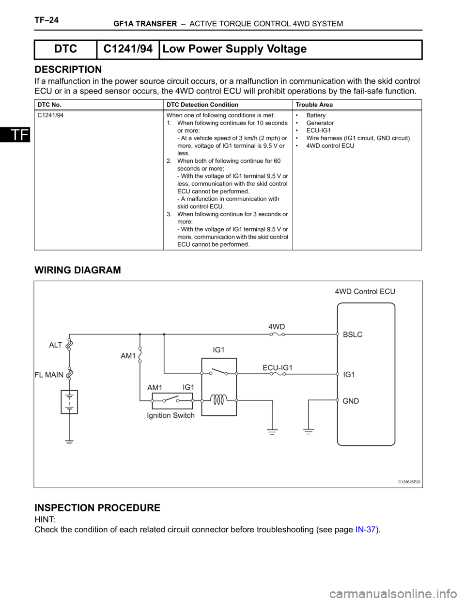
If a malfunction in the power source circuit occurs, or a malfunction in communication with the skid control
ECU or in a speed sensor occurs, the 4WD control ECU will prohibit operations by the fail-safe function.
WIRING DIAGRAM
INSPECTION PROCEDURE
HINT:
Check the condition of each related circuit connector before troubleshooting (see page IN-37).
DTC C1241/94 Low Power Supply Voltage
DTC No. DTC Detection Condition Trouble Area
C1241/94 When one of following conditions is met:
1. When following continues for 10 seconds
or more:
- At a vehicle speed of 3 km/h (2 mph) or
more, voltage of IG1 terminal is 9.5 V or
less.
2. When both of following continue for 60
seconds or more:
- With the voltage of IG1 terminal 9.5 V or
less, communication with the skid control
ECU cannot be performed.
- A malfunction in communication with
skid control ECU.
3. When following continue for 3 seconds or
more:
- With the voltage of IG1 terminal 9.5 V or
more, communication with the skid control
ECU cannot be performed.•Battery
• Generator
•ECU-IG1
• Wire harness (IG1 circuit, GND circuit)
• 4WD control ECU
C128626E02