Page 393 of 2000
SS–72SERVICE SPECIFICATIONS – DRIVE SHAFT
SS
TORQUE SPECIFICATIONS
(2005/11-2006/01)
Drive shaft
Part Tightened N*m kgf*cm ft.*lbf
Front wheel
Rear wheel103 1,050 76
front suspension lower arm x Lower ball joint 92 938 68
Front axle hub nut 216 2,203 159
Drive shaft bearing bracket x Engine 63.7 650 47
Drive shaft bearing case
bolt2WD 63.7 650 47
Drive shaft bearing
bracket x Drive shaft4WD 32.4 330 24
Page 394 of 2000
SERVICE SPECIFICATIONS – DRIVE SHAFTSS–73
SS
TORQUE SPECIFICATIONS
(2006/01- )
Drive shaft
Part Tightened N*m kgf*cm ft.*lbf
Front wheel
Rear wheel103 1,050 76
front suspension lower arm x Lower ball joint 92 938 68
Front axle hub nut
26 216 2,203 159
30 292 2,978 215
Drive shaft bearing bracket x Engine 63.7 650 47
Drive shaft bearing case
bolt2WD 63.7 650 47
Drive shaft bearing
bracket x Drive shaft4WD 32.4 330 24
Page 684 of 2000

EM–382GR-FE ENGINE MECHANICAL – ENGINE ASSEMBLY
EM
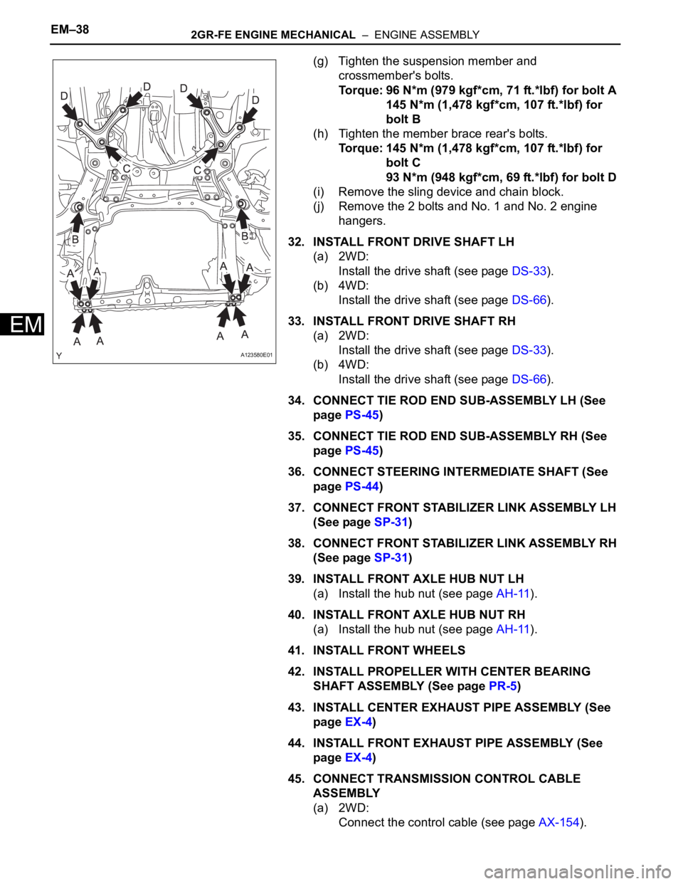
(g) Tighten the suspension member and
crossmember's bolts.
Torque: 96 N*m (979 kgf*cm, 71 ft.*lbf) for bolt A
145 N*m (1,478 kgf*cm, 107 ft.*lbf) for
bolt B
(h) Tighten the member brace rear's bolts.
Torque: 145 N*m (1,478 kgf*cm, 107 ft.*lbf) for
bolt C
93 N*m (948 kgf*cm, 69 ft.*lbf) for bolt D
(i) Remove the sling device and chain block.
(j) Remove the 2 bolts and No. 1 and No. 2 engine
hangers.
32. INSTALL FRONT DRIVE SHAFT LH
(a) 2WD:
Install the drive shaft (see page DS-33).
(b) 4WD:
Install the drive shaft (see page DS-66).
33. INSTALL FRONT DRIVE SHAFT RH
(a) 2WD:
Install the drive shaft (see page DS-33).
(b) 4WD:
Install the drive shaft (see page DS-66).
34. CONNECT TIE ROD END SUB-ASSEMBLY LH (See
page PS-45)
35. CONNECT TIE ROD END SUB-ASSEMBLY RH (See
page PS-45)
36. CONNECT STEERING INTERMEDIATE SHAFT (See
page PS-44)
37. CONNECT FRONT STABILIZER LINK ASSEMBLY LH
(See page SP-31)
38. CONNECT FRONT STABILIZER LINK ASSEMBLY RH
(See page SP-31)
39. INSTALL FRONT AXLE HUB NUT LH
(a) Install the hub nut (see page AH-11).
40. INSTALL FRONT AXLE HUB NUT RH
(a) Install the hub nut (see page AH-11).
41. INSTALL FRONT WHEELS
42. INSTALL PROPELLER WITH CENTER BEARING
SHAFT ASSEMBLY (See page PR-5)
43. INSTALL CENTER EXHAUST PIPE ASSEMBLY (See
page EX-4)
44. INSTALL FRONT EXHAUST PIPE ASSEMBLY (See
page EX-4)
45. CONNECT TRANSMISSION CONTROL CABLE
ASSEMBLY
(a) 2WD:
Connect the control cable (see page AX-154).
A123580E01
Page 992 of 2000

AX–198U140F AUTOMATIC TRANSAXLE – AUTOMATIC TRANSAXLE UNIT
AX
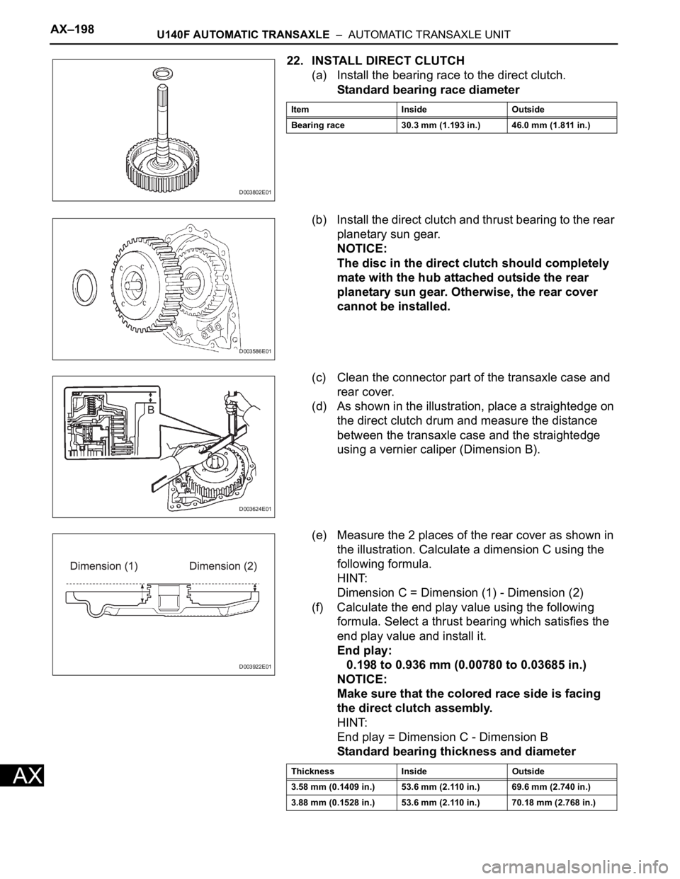
22. INSTALL DIRECT CLUTCH
(a) Install the bearing race to the direct clutch.
Standard bearing race diameter
(b) Install the direct clutch and thrust bearing to the rear
planetary sun gear.
NOTICE:
The disc in the direct clutch should completely
mate with the hub attached outside the rear
planetary sun gear. Otherwise, the rear cover
cannot be installed.
(c) Clean the connector part of the transaxle case and
rear cover.
(d) As shown in the illustration, place a straightedge on
the direct clutch drum and measure the distance
between the transaxle case and the straightedge
using a vernier caliper (Dimension B).
(e) Measure the 2 places of the rear cover as shown in
the illustration. Calculate a dimension C using the
following formula.
HINT:
Dimension C = Dimension (1) - Dimension (2)
(f) Calculate the end play value using the following
formula. Select a thrust bearing which satisfies the
end play value and install it.
End play:
0.198 to 0.936 mm (0.00780 to 0.03685 in.)
NOTICE:
Make sure that the colored race side is facing
the direct clutch assembly.
HINT:
End play = Dimension C - Dimension B
Standard bearing thickness and diameter
D003802E01
Item Inside Outside
Bearing race 30.3 mm (1.193 in.) 46.0 mm (1.811 in.)
D003586E01
D003624E01
D003922E01
Thickness Inside Outside
3.58 mm (0.1409 in.) 53.6 mm (2.110 in.) 69.6 mm (2.740 in.)
3.88 mm (0.1528 in.) 53.6 mm (2.110 in.) 70.18 mm (2.768 in.)
Page 1075 of 2000
U151E AUTOMATIC TRANSAXLE – AUTOMATIC TRANSAXLE UNITAX–201
AX
49. REMOVE BRAKE APPLY TUBE
(a) Remove the bolt, clamp and brake apply tube.
(b) Remove the clutch apply tube.
(c) Remove the brake apply tube from the clamp.
NOTICE:
Do not bend the tubes.
50. REMOVE DIRECT CLUTCH ASSEMBLY
(a) Remove the thrust bearing and the direct clutch
from the transaxle case.
51. REMOVE OVERDRIVE DIRECT CLUTCH HUB SUB-
ASSEMBLY
(a) Remove the thrust bearing race, thrust bearing and
overdrive direct clutch hub from the planetary gear.
52. INSPECT OVERDRIVE DIRECT CLUTCH DRUM SUB-
ASSEMBLY (See page AX-209)
53. REMOVE REAR PLANETARY SUN GEAR ASSEMBLY
(a) Remove the rear planetary sun gear from the
transaxle case.
(b) Remove the thrust needle roller bearing and thrust
bearing race from the rear planetary sun gear.
D026391E05
D026403E06
D026392E09
D026714E05
D026404E07
Page 1099 of 2000

U151E AUTOMATIC TRANSAXLE – AUTOMATIC TRANSAXLE UNITAX–225
AX
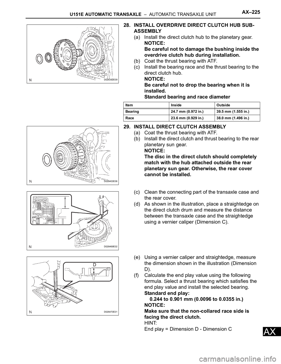
28. INSTALL OVERDRIVE DIRECT CLUTCH HUB SUB-
ASSEMBLY
(a) Install the direct clutch hub to the planetary gear.
NOTICE:
Be careful not to damage the bushing inside the
overdrive clutch hub during installation.
(b) Coat the thrust bearing with ATF.
(c) Install the bearing race and the thrust bearing to the
direct clutch hub.
NOTICE:
Be careful not to drop the bearing when it is
installed.
Standard bearing and race diameter
29. INSTALL DIRECT CLUTCH ASSEMBLY
(a) Coat the thrust bearing with ATF.
(b) Install the direct clutch and thrust bearing to the rear
planetary sun gear.
NOTICE:
The disc in the direct clutch should completely
match with the hub attached outside the rear
planetary sun gear. Otherwise, the rear cover
cannot be installed.
(c) Clean the connecting part of the transaxle case and
the rear cover.
(d) As shown in the illustration, place a straightedge on
the direct clutch drum and measure the distance
between the transaxle case and the straightedge
using a vernier caliper (Dimension C).
(e) Using a vernier caliper and straightedge, measure
the dimension shown in the illustration (Dimension
D).
(f) Calculate the end play value using the following
formula. Select a thrust bearing which satisfies the
end play value and install the selected bearing.
Standard end play:
0.244 to 0.901 mm (0.0096 to 0.0355 in.)
NOTICE:
Make sure that the non-collared race side is
facing the direct clutch.
HINT:
End play = Dimension D - Dimension C
D026392E09
Item Inside Outside
Bearing 24.7 mm (0.972 in.) 39.5 mm (1.555 in.)
Race 23.6 mm (0.929 in.) 38.0 mm (1.496 in.)
D026403E06
D026469E02
D026470E01
Page 1180 of 2000
AX–202U151F AUTOMATIC TRANSAXLE – AUTOMATIC TRANSAXLE UNIT
AX
49. REMOVE BRAKE APPLY TUBE
(a) Remove the bolt, clamp and brake apply tube.
(b) Remove the clutch apply tube.
(c) Remove the brake apply tube from the clamp.
NOTICE:
Do not bend the tubes.
50. REMOVE DIRECT CLUTCH ASSEMBLY
(a) Remove the thrust bearing and the direct clutch
from the transaxle case.
51. REMOVE OVERDRIVE DIRECT CLUTCH HUB SUB-
ASSEMBLY
(a) Remove the thrust bearing race, thrust bearing and
overdrive direct clutch hub from the planetary gear.
52. INSPECT OVERDRIVE DIRECT CLUTCH DRUM SUB-
ASSEMBLY (See page AX-210)
53. REMOVE REAR PLANETARY SUN GEAR ASSEMBLY
(a) Remove the rear planetary sun gear from the
transaxle case.
(b) Remove the thrust needle roller bearing and thrust
bearing race from the rear planetary sun gear.
D026391E05
D026403E06
D026392E09
D026714E05
D026404E07
Page 1204 of 2000

AX–226U151F AUTOMATIC TRANSAXLE – AUTOMATIC TRANSAXLE UNIT
AX
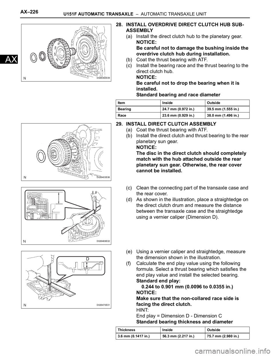
28. INSTALL OVERDRIVE DIRECT CLUTCH HUB SUB-
ASSEMBLY
(a) Install the direct clutch hub to the planetary gear.
NOTICE:
Be careful not to damage the bushing inside the
overdrive clutch hub during installation.
(b) Coat the thrust bearing with ATF.
(c) Install the bearing race and the thrust bearing to the
direct clutch hub.
NOTICE:
Be careful not to drop the bearing when it is
installed.
Standard bearing and race diameter
29. INSTALL DIRECT CLUTCH ASSEMBLY
(a) Coat the thrust bearing with ATF.
(b) Install the direct clutch and thrust bearing to the rear
planetary sun gear.
NOTICE:
The disc in the direct clutch should completely
match with the hub attached outside the rear
planetary sun gear. Otherwise, the rear cover
cannot be installed.
(c) Clean the connecting part of the transaxle case and
the rear cover.
(d) As shown in the illustration, place a straightedge on
the direct clutch drum and measure the distance
between the transaxle case and the straightedge
using a vernier caliper (Dimension D).
(e) Using a vernier caliper and straightedge, measure
the dimension shown in the illustration.
(f) Calculate the end play value using the following
formula. Select a thrust bearing which satisfies the
end play value and install the selected bearing.
Standard end play:
0.244 to 0.901 mm (0.0096 to 0.0355 in.)
NOTICE:
Make sure that the non-collared race side is
facing the direct clutch.
HINT:
End play = Dimension D - Dimension C
Standard bearing thickness and diameter
D026392E09
Item Inside Outside
Bearing 24.7 mm (0.972 in.) 39.5 mm (1.555 in.)
Race 23.6 mm (0.929 in.) 38.0 mm (1.496 in.)
D026403E06
D026469E02
D026470E01
Thickness Inside Outside
3.6 mm (0.1417 in.) 56.3 mm (2.217 in.) 75.7 mm (2.980 in.)