2006 TOYOTA RAV4 change wheel
[x] Cancel search: change wheelPage 1335 of 2000

GF1A TRANSFER – ACTIVE TORQUE CONTROL 4WD SYSTEMTF–7
TF2. DRIVING FUNCTION
Ambient Temperature Detects external ambient temperature and inputs it into body ECU
Electromagnetic Coupling Based on amount of current sent from 4WD control ECU, torque is
distributed to rear wheels
4WD Lock Switch Change of side auto mode for lock mode
4WD Lock Mode Indicator Light Lock mode control status is communicated to driver through indicator
light illumination
When lock mode is turned ON, indicator light blinks twice and then
remains illuminated.
When lock mode is turned OFF, indicator light turns OFF. Component Function
Vehicle Condition Status
Control at Vehicle Startup This controls the amount of sideway sliding that occurs at rear of
vehicles when accelerating from stop to improve acceleration and hill
climbing capacity
Slip Control at Vehicle Startup This helps prevent vehicle from sliding sideways. When accelerating a
stopped vehicle with the steering wheel turned, it ensures steering
stability
Slip Control This ensures high turning performance and that stability is not affected
by road surface conditions during mid and high speed running
Control During Acceleration This controls straight-line running when accelerating during mid and
high speeds to ensure straight-line stability of the vehicle
Page 1337 of 2000

GF1A TRANSFER – ACTIVE TORQUE CONTROL 4WD SYSTEMTF–9
TF
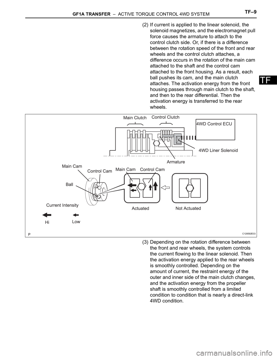
(2) If current is applied to the linear solenoid, the
solenoid magnetizes, and the electromagnet pull
force causes the armature to attach to the
control clutch side. Or, if there is a difference
between the rotation speed of the front and rear
wheels and the control clutch attaches, a
difference occurs in the rotation of the main cam
attached to the shaft and the control cam
attached to the front housing. As a result, each
ball pushes its cam, and the main clutch
attaches. The activation energy from the front
housing passes through main clutch to the shaft,
and then to the rear differential. Then the
activation energy is transferred to the rear
wheels.
(3) Depending on the rotation difference between
the front and rear wheels, the system controls
the current flowing to the linear solenoid. Then
the activation energy applied to the rear wheels
is smoothly controlled. Depending on the
amount of current, the restraint energy of the
outer and inner side of the main clutch changes,
and the activation energy from the propeller
shaft is smoothly controlled from a limited
condition to condition that is nearly a direct-link
4WD condition.
C128592E03
Page 1341 of 2000

GF1A TRANSFER – ACTIVE TORQUE CONTROL 4WD SYSTEMTF–13
TF
TEST MODE PROCEDURE
1. DESCRIPTION
HINT:
When using a chassis dynamometer, brake tester, etc. to
perform a vehicle test, activate test mode to avoid a
"different tire diameter installed" incorrect judgment.
Test mode does not have a 4WD parameter. Test mode
is activated because it will prohibit a different tire
diameter judgment.
2. ACTIVATE TEST MODE
HINT:
Activate test mode before using a chassis dynamometer,
brake tester, etc. to perform a vehicle test.
(a) Check that the ignition switch is OFF.
(b) Use either of the following methods to change the
4WD ECU to test mode.
(1) Test mode activation through intelligent tester
(with CAM VIM).
• Connect the intelligent tester (with CAM VIM)
to the DLC3 connector and turn the ignition
switch ON. Using the test mode activation
function (mode 10), activate test mode.
(2) Test mode activation by shorting TS terminal
• With the ignition switch OFF, short-circuit the
TS and CG terminals of the DLC3 connector.
Then turn the ignition switch ON to activate
test mode.
NOTICE:
When the ignition switch is turned from
OFF to ON, the 4WD indicator light will
illuminate for 4 seconds. Then it will turn
off.
4WD Lock Mode indicator
HINT:
When the ignition switch is ON and the 4WD
lock switch is turned from OFF to ON, the
4WD lock mode indicator blinks twice and
then illuminates.
If the indicator does not illuminate, check the
bulb for burnout. Also, inspect the wire
harness between the 4WD ECU and
combination meter.
Control Status 4WD Control Status
During test mode Different tire diameter malfunction judgment (detection that tire
diameter of 4 wheels are not same) is not performed.
Other than above item, normal control is performed.
- 4WD lock switch OFF (4WD auto mode status)
- 4WD lock switch ON (4WD lock mode status)
4WD Lock Switch OFF Illuminates for 4 seconds, then turns
OFF
4WD Lock Switch ON Remains illuminated
Page 1348 of 2000

TF–20GF1A TRANSFER – ACTIVE TORQUE CONTROL 4WD SYSTEM
TF
FAIL-SAFE CHART
1. FAIL-SAFE FUNCTION
• If following malfunctions occur, the 4WD control ECU
will stop the function of 4WD control system or partly
change the function to control the system.
• If a malfunction occurs in the sensor signal or
actuator, the flow of electricity to the linear solenoid of
the electrical coupling is prohibited. As a result, the
system enters front wheel drive condition.
• When a component of the system malfunctions and
the fail-safe function activates, the component
operation is prohibited. However, if the system is
controlling the component and the fail-safe function
activates, the system operation is gradually stopped
to prevent sudden changes in the vehicle condition.
• When system control is not possible, the warning light
is illuminated to stop operation of the system
operation.
Page 1456 of 2000

AH–16AXLE – REAR AXLE HUB AND BEARING
AH
ON-VEHICLE INSPECTION
1. REMOVE REAR WHEEL
2. DISCONNECT REAR DRIVE SHAFT ASSEMBLY LH
(for 4WD)
(a) Disconnect the drive shaft (see page DS-69).
3. REMOVE REAR DISC BRAKE CYLINDER ASSEMBLY
LH (See page BR-55)
4. REMOVE REAR DISC (See page BR-57)
5. CHECK BEARING BACKLASH AND AXLE HUB
DEVIATION
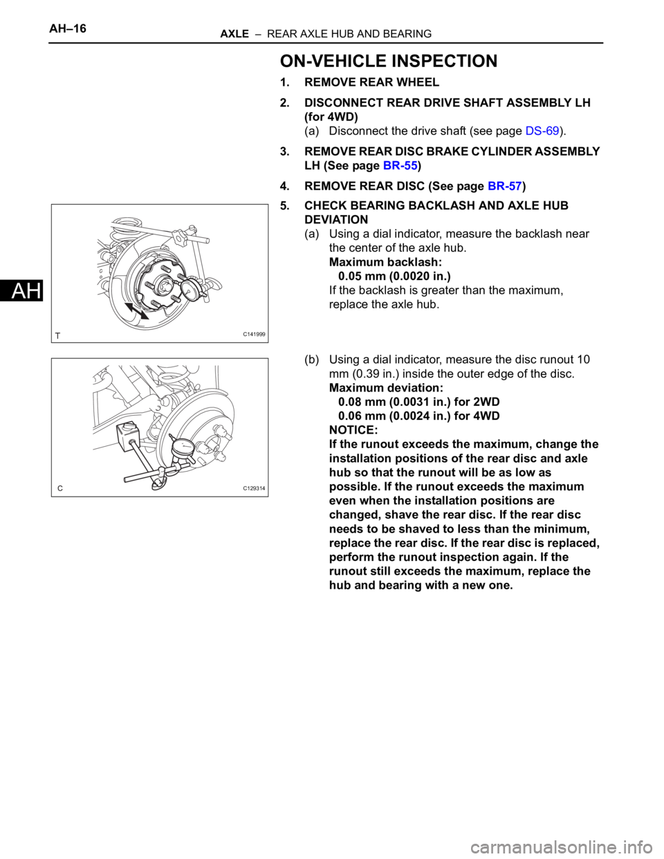
(a) Using a dial indicator, measure the backlash near
the center of the axle hub.
Maximum backlash:
0.05 mm (0.0020 in.)
If the backlash is greater than the maximum,
replace the axle hub.
(b) Using a dial indicator, measure the disc runout 10
mm (0.39 in.) inside the outer edge of the disc.
Maximum deviation:
0.08 mm (0.0031 in.) for 2WD
0.06 mm (0.0024 in.) for 4WD
NOTICE:
If the runout exceeds the maximum, change the
installation positions of the rear disc and axle
hub so that the runout will be as low as
possible. If the runout exceeds the maximum
even when the installation positions are
changed, shave the rear disc. If the rear disc
needs to be shaved to less than the minimum,
replace the rear disc. If the rear disc is replaced,
perform the runout inspection again. If the
runout still exceeds the maximum, replace the
hub and bearing with a new one.
C141999
C129314
Page 1502 of 2000

TW–30TIRE AND WHEEL – TIRE PRESSURE WARNING SYSTEM
TW
(e) Rapidly release the pressure from each wheel by
approximately 40 kPa (0.4 kgf/cm
2, 5.8 psi) for 30
seconds or more.
(1) Check that each tire pressure data displayed on the
intelligent tester screen changes.
OK:
The tire pressure data displayed on the
intelligent tester screen changes with the
value of the tire pressure.
NOTICE:
• It may take up to 1 minute to display the
updated tire pressure data.
• When the TIREPRESS data (IDs 1 to 5)
changes, reset the tire pressure of the tires to
the specified value, rotate the tires 90 to 270
and recheck.
(2) After confirming that the tire pressure data displayed
on the intelligent tester screen has changed, set the
pressure of each tire to the specified value.
Standard pressure:
220 kPa (2.2 kgf/cm
2, 32 psi)
HINT:
If the tire pressure data displayed on the intelligent
tester screen has not changed after rechecking, go
to the troubleshooting procedures of DTCs C2121/
21 to C2125/25 which indicate transmission or
reception malfunctions (see page TW-28).
NG
OK
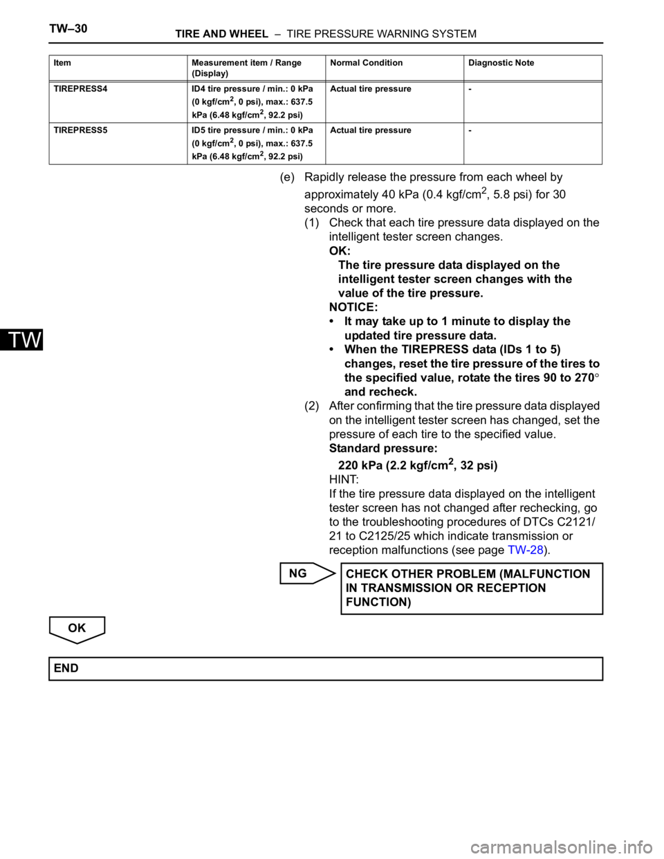
TIREPRESS4 ID4 tire pressure / min.: 0 kPa
(0 kgf/cm2, 0 psi), max.: 637.5
kPa (6.48 kgf/cm2, 92.2 psi) Actual tire pressure -
TIREPRESS5 ID5 tire pressure / min.: 0 kPa
(0 kgf/cm
2, 0 psi), max.: 637.5
kPa (6.48 kgf/cm2, 92.2 psi) Actual tire pressure - Item Measurement item / Range
(Display) Normal Condition Diagnostic Note
CHECK OTHER PROBLEM (MALFUNCTION
IN TRANSMISSION OR RECEPTION
FUNCTION)
END
Page 1505 of 2000

TIRE AND WHEEL – TIRE PRESSURE WARNING SYSTEMTW–33
TW
(e) Rapidly release the tire pressure from any tire by 40 kPa
(0.4 kgf/cm
2, 5.8 psi) for 30 seconds or more.
HINT:
• Identify the malfunctioning tire pressure warning valve
and transmitter by rapidly releasing the tire pressures
from each tire.
• Record which TIREPRESS data (ID1 to ID5)
corresponds to each tire.
(f) Check the DATA LIST.
Result
NOTICE:
• It may take up to 1 minute to display the updated
tire pressure data.
• When the TIREPRESS data (IDs 1 to 5) changes,
reset the tire pressure of the tires to the specified
value, rotate the tires 90 to 270
and recheck.
• When the transmitter is normal, record the tire
location and the transmitter ID.
(g) When the TIREPRESS data (IDs 1 to 5) changes, repeat
the same procedure on the rest of the tires (one by one)
to identify which tire pressure warning valve and
transmitter the DTC corresponds to.
(h) Set the pressure of each tire to the specified value.
Standard pressure:
220 kPa (2.2 kgf/cm
2, 32 psi)
(i) Check all transmitters of the tires.
Result
B
C
A
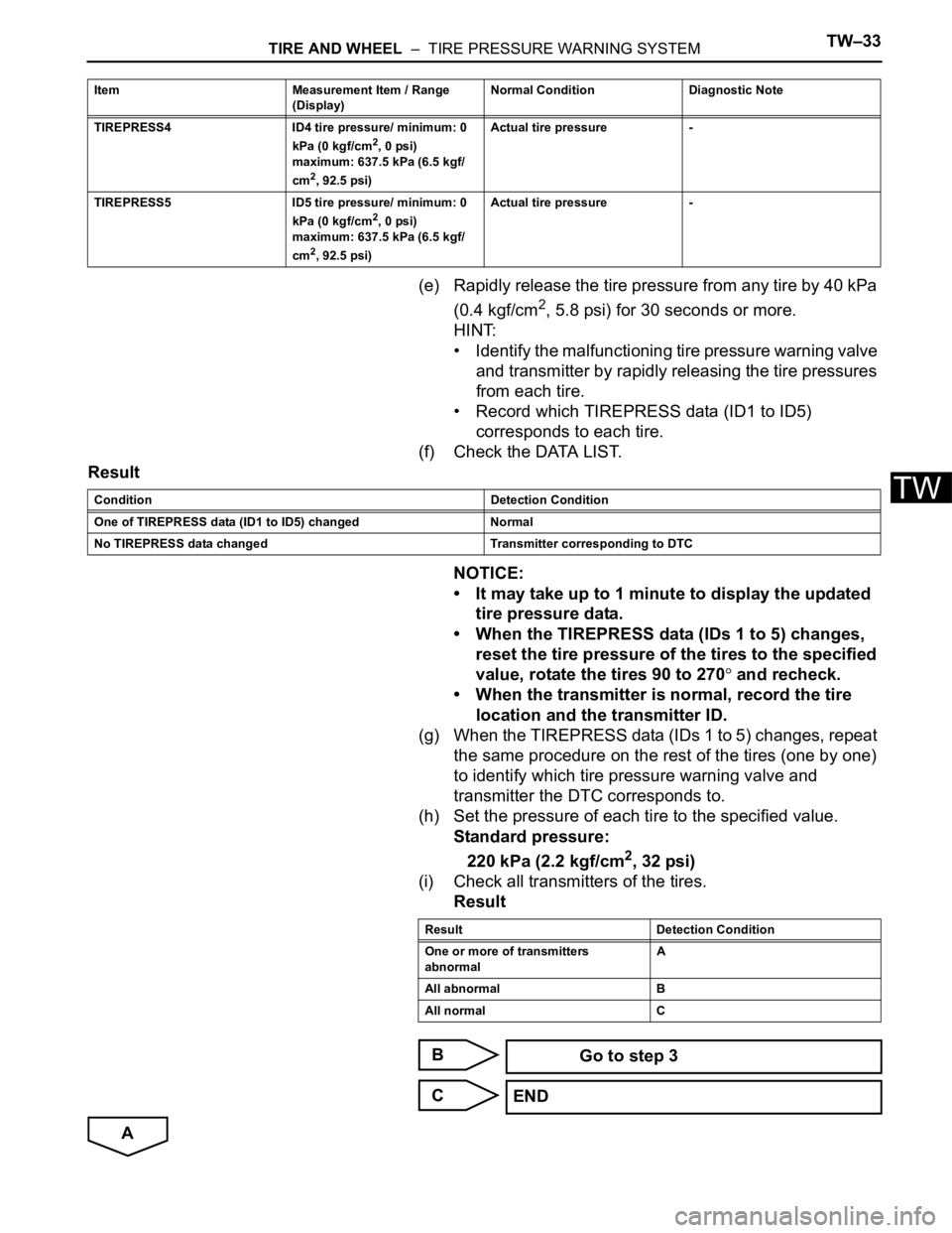
TIREPRESS4 ID4 tire pressure/ minimum: 0
kPa (0 kgf/cm2, 0 psi)
maximum: 637.5 kPa (6.5 kgf/
cm
2, 92.5 psi)Actual tire pressure -
TIREPRESS5 ID5 tire pressure/ minimum: 0
kPa (0 kgf/cm
2, 0 psi)
maximum: 637.5 kPa (6.5 kgf/
cm
2, 92.5 psi)Actual tire pressure - Item Measurement Item / Range
(Display)Normal Condition Diagnostic Note
Condition Detection Condition
One of TIREPRESS data (ID1 to ID5) changed Normal
No TIREPRESS data changed Transmitter corresponding to DTC
Result Detection Condition
One or more of transmitters
abnormalA
All abnormal B
All normal C
Go to step 3
END
Page 1557 of 2000

BC–54BRAKE CONTROL – VEHICLE STABILITY CONTROL SYSTEM
BC
GEAR POSITION Gear position information FAIL
1st
2nd
3rd
4th
5th
6th
P, N
R
NOT R
LEVER POSITION Shift lever position information FAIL
1st
2nd
3rd
4th
5th
6th/B
D/M
P, N
R
OPERATED SYSTEM Operated system status ABS: ABS activated
VSC: VSC activated
TRC: TRC activated
BA: BA activated
FAIL: Fail safe mode activated
HA-CTRL: Hill-start assist control activated
SYS: System prohibited
NON: No system activated
MAS CYL PRESS 1 Master cylinder pressure sensor reading Brake pedal released: 0.3 V to 0.9 V
Brake pedal depressed: 0.8 V to 4.5 V
M/C Sensor Grade Master cylinder pressure sensor change Min.: -30 MPa/s
Max.: 225 MPa/s
YAW RATE Yaw rate sensor reading Min.: -128 deg/s
Max.: 127 deg/s
STEERING SEN Steering sensor reading Left turn: Increase
Right turn: Decrease
LATERAL G Lateral G
Min.: -25.11 m/s
2
Max.: 24.91 m/s2
FORWARD&REA G Forward and backward G
Min.: -25.11 m/s2
Max.: 24.91 m/s2
FR WHEEL SPD FR wheel speed Min.: 0 km/h (0 mph)
Max.: 326.4 km/h (202.8 mph)
FL WHEEL SPD FL wheel speed Min.: 0 km/h (0 mph)
Max.: 326.4 km/h (202.8 mph)
RR WHEEL SPD RR wheel speed Min.: 0 km/h (0 mph)
Max.: 326.4 km/h (202.8 mph)
RL WHEEL SPD RL wheel speed Min.: 0 km/h (0 mph)
Max.: 326.4 km/h (202.8 mph)
VEHICLE SPD Vehicle speed Min.: 0 km/h (0 mph)
Max.: 326.4 km/h (202.8 mph)
SPD GARDE Vehicle speed grade
Min.: -25.11 m/s
2
Max.: 24.91 m/s2
ENGINE TORQUE Real engine torque Min.: -1024 Nm
Max.: 1023 Nm
ACCELERATOR % Accelerator pedal opening angle % Min.: 0%
Max.: 128%
INSPECTION MODE Inspection mode OTHER: Normal
INSPECT: Service Item (Display) Measurement Item Reference Values