2006 TOYOTA RAV4 abs sensor
[x] Cancel search: abs sensorPage 52 of 2000

ENGINE - 2AZ-FE ENGINE
00REG22Y
To Intake Manifold
Purge VSV
Purge Air
Line
ECMFuel Tank
Canister Filter
Fresh Air LineRefueling Valve
Canister Pump Module
Ve n t
Va l v e
Leak Detection Pump
& Pump Motor
Canister
Pressure SensorCanisterP M
EG-55
System Diagram
Function of Main Components
ComponentFunction
CanisterContains activated charcoal to absorb the vapor gas that is created in the
fuel tank.
Refueling
Controls the flow rate of the vapor gas from the fuel tank to the canister
when the system is purging or during refueling.
Refueling
Va l v eRestrictor PassagePrevents a large amount of vacuum during purge operation or system
monitoring operation from affecting the pressure in the fuel tank.
Fresh Air LineFresh air goes into the canister and the cleaned drain air goes out into
the atmosphere.
Vent ValveOpens and closes the fresh air line in accordance with the signals from
the ECM.
Canister
Pump ModuleLeak Detection
PumpApplies vacuum pressure to the EVAP control system in accordance
with the signals from the ECM.
p
Canister
Pressure SensorDetects the pressure in the EVAP control system and sends the signals
to the ECM.
Purge VSV
Opens in accordance with the signals from the ECM when the system
is purging, in order to send the vapor gas that was absorbed by the
canister into the intake manifold. In system monitoring mode, this valve
controls the introduction of the vacuum into the fuel tank.
Canister FilterPrevents dust and debris in the fresh air from entering the system.
ECM
Controls the canister pump module and purge VSV in accordance with
the signals from various sensors, in order to achieve a purge volume that
suits the driving conditions. In addition, the ECM monitors the system
for any leakage and outputs a DTC if a malfunction is found.
Page 221 of 2000

INTRODUCTION – TERMSIN–49
IN
IAT Intake Air Temperature Intake or Inlet Air Temperature
ICM Ignition Control Module -
IFI Indirect Fuel Injection Indirect Injection (IDL)
IFS Inertia Fuel-Shutoff -
ISC Idle Speed Control -
KS Knock Sensor Knock Sensor
MAF Mass Airflow Air Flow Meter
MAP Manifold Absolute Pressure Manifold Pressure Intake Vacuum
MC Mixture ControlElectric Bleed Air Control Valve (EBCV)
Mixture Control Valve (MCV)
Electric Air Control Valve (EACV)
MDP Manifold Differential Pressure -
MFI Multiport Fuel Injection Electronic Fuel Injection (EFI)
MIL Malfunction Indicator Lamp Check Engine Lamp
MST Manifold Surface Temperature -
MVZ Manifold Vacuum Zone -
NVRAM Non-Volatile Random Access Memory -
O2S Oxygen Sensor Oxygen Sensor, O2 Sensor (O2S)
OBD On-Board Diagnostic On-Board Diagnostic System (OBD)
OC Oxidation Catalytic Converter Oxidation Catalyst Converter (OC), CCo
OL Open Loop Open Loop
PAIR Pulsed Secondary Air Injection Air Suction (AS)
PCM Powertrain Control Module -
PNP Park/Neutral Position -
PROM Programmable Read Only Memory -
PSP Power Steering Pressure -
PTOX Periodic Trap OxidizerDiesel Particulate Filter (DPF)
Diesel Particulate Trap (DPT)
RAM Random Access Memory Random Access Memory (RAM)
RM Relay Module -
ROM Read Only Memory Read Only Memory (ROM)
RPM Engine Speed Engine Speed
SC Supercharger Supercharger
SCB Supercharger Bypass E-ABV
SFI Sequential Multiport Fuel Injection Electronic Fuel Injection (EFI), Sequential Injection
SPL Smoke Puff Limiter -
SRI Service Reminder Indicator -
SRT System Readiness Test -
ST Scan Tool -
TB Throttle Body Throttle Body
TBI Throttle Body Fuel InjectionSingle Point Injection
Central Fuel Injection (Ci)
TC Turbocharger Turbocharger
TCC Torque Converter Clutch Torque Converter
TCM Transmission Control Module Transmission ECU, ECT ECU
TP Throttle Position Throttle Position
TR Transmission Range -
TVV Thermal Vacuum ValveBimetallic Vacuum Switching Valve (BVSV)
Thermostatic Vacuum Switching Valve (TVSV) SAE
ABBREVIATIONSSAE TERMS TOYOTA TERMS ( )-ABBREVIATIONS
Page 405 of 2000

AH–8AXLE – FRONT AXLE HUB
AH
10. REMOVE STEERING KNUCKLE WITH AXLE HUB
(a) Remove the 2 bolts and 2 nuts, and disconnect the
shock absorber from the steering knuckle.
HINT:
While fixing the nuts in place, loosen and remove
the bolts.
(b) Put matchmarks on the drive shaft and the axle hub.
(c) Using a plastic-faced hammer, remove the steering
knuckle with axle hub.
NOTICE:
Be careful not to damage the boot and speed
sensor rotor. Do not excessively push out the
drive shaft from the axle assembly.
11. REMOVE FRONT LOWER BALL JOINT ASSEMBLY
LH (See page SP-27)
12. REMOVE FRONT AXLE HUB SUB-ASSEMBLY LH
(a) Remove the 4 bolts and axle hub from the steering
knuckle.
NOTICE:
Do not place the hub and bearing's magnet rotor
side so that it is facing downward, and do not
allow the magnet rotor side to become damaged
or contact foreign matter.
(b) Remove the dust cover from the steering knuckle.
C127533
C129488E01
C127536
Page 497 of 2000

2AZ-FE ENGINE CONTROL SYSTEM – SFI SYSTEMES–43
ES
KNOCK FB VAL Feedback value of knocking -
ACCEL POS #1Absolute Accelerator Pedal Position (APP)
No.1-
ACCEL POS #2 Absolute APP No. 2 -
THROTTLE POS Throttle sensor positioning -
THROTTLE POS Throttle position -
THROTTLE POS #2 Throttle sensor positioning #2 -
THROTTLE MOT Throttle motor -
O2S B1 S2 Heated oxygen sensor outputPerforming INJ VOL or A/F CONTROL
function of ACTIVE TEST enables technician
to check output voltage of sensor
AFS B1 S1 A/F sensor outputPerforming INJ VOL or A/F CONTROL
function of ACTIVE TEST enables technician
to check output voltage of sensor
TOTAL FT #1 Total fuel trim -
SHORT FT #1 Short-term fuel trimShort-term fuel compensation used to
maintain air-fuel ratio at stoichiometric air-fuel
ratio
LONG FT #1 Long-term fuel trimOverall fuel compensation carried out in long-
term to compensate a continual deviation of
short-term fuel trim from central valve
FUEL SYS #1 Fuel system status• OL (Open Loop): Has not yet satisfied
conditions to go closed loop
• CL (Closed Loop): Using A/F sensor as
feedback for fuel control
• OL DRIVE: Open loop due to driving
conditions (fuel enrichment)
• OL FAULT: Open loop due to detected
system fault
• CL FAULT: Closed loop but A/F sensor,
which used for fuel control malfunctioning
O2FT B1 S2 Fuel trim at heated oxygen sensor -
AF FT B1 S1 Fuel trim at A/F sensor -
AFS B1 S1 A/F sensor current -
CAT TEMP B1S1 Estimated catalyst temperature (sensor 1) -
CAT TEMP B1S2 Estimated catalyst temperature (sensor 2) -
S O2S B1S2Sub heated oxygen sensor impedance
(sensor 2)-
INI COOL TEMP Engine coolant temperature at engine start -
INI INTAKE TEMP Intake air temperature at engine start -
INJ VOL Injection volume -
STARTER SIG Starter switch (STSW) signal -
PS SW Power steering signal -
PS SIGNAL Power steering signal (history)Signal status usually ON until ignition switch
turned OFF
CTP SW Closed throttle position switch -
A/C SIGNAL A/C signal -
PNP SW (NSW) Park/Neutral Position (PNP) switch signal -
ELECT LOAD SIG Electrical load signal -
STOP LIGHT SW Stop light switch -
BATTERY VOLTAGE Battery voltage -
ATM PRESSURE Atmosphere pressure -
EVAP (Purge) VSV EVAP Purge VSV -
FUEL PUMP/SPD Fuel pump/speed status -LABEL
(Intelligent Tester Display)Measurement Item Diagnostic Note
Page 571 of 2000

2GR-FE ENGINE CONTROL SYSTEM – SFI SYSTEMES–47
ES
KNOCK FB VAL Feedback value of knocking -
ACCEL POS #1Absolute Accelerator Pedal Position (APP)
No.1-
ACCEL POS #2 Absolute APP No. 2 -
THROTTLE POS Throttle sensor positioning -
THROTTLE POS Throttle position -
THROTTLE POS #2 Throttle sensor positioning #2 -
THROTTLE MOT Throttle motor -
O2S B1 S2
O2S B2 S2Heated oxygen sensor outputPerforming INJ VOL or A/F CONTROL
function of ACTIVE TEST enables technician
to check output voltage of sensor
AFS B1 S1
AFS B2 S1A/F sensor outputPerforming INJ VOL or A/F CONTROL
function of ACTIVE TEST enables technician
to check output voltage of sensor
TOTAL FT #1
TOTAL FT #2Total fuel trim -
SHORT FT #1
SHORT FT #2Short-term fuel trimShort-term fuel compensation used to
maintain air-fuel ratio at stoichiometric air-fuel
ratio
LONG FT #1
LONG FT #2Long-term fuel trimOverall fuel compensation carried out in long-
term to compensate a continual deviation of
short-term fuel trim from central valve
O2FT B1 S2
O2FT B2 S2Fuel trim at heated oxygen sensor -
AF FT B1 S1
AF FT B2 S1Fuel trim at A/F sensor-
AFS B1 S1
AFS B2 S1A/F sensor current-
CAT TEMP B1S1
CAT TEMP B2S1Estimated catalyst temperature (sensor 1)-
CAT TEMP B1S2
CAT TEMP B2S2Estimated catalyst temperature (sensor 2)-
S O2S B1S2
S O2S B2S2Sub heated oxygen sensor impedance
(sensor 2)-
INI COOL TEMP Engine coolant temperature at engine start -
INI INTAKE TEMP Intake air temperature at engine start -
INJ VOL Injection volume -
STARTER SIG Starter switch (STSW) signal -
PS SW Power steering signal -
PS SIGNAL Power steering signal (history)Signal status usually ON until ignition switch
turned OFF
CTP SW Closed throttle position switch -
A/C SIGNAL A/C signal -
PNP SW (NSW) Park/Neutral Position (PNP) switch signal -
ELECT LOAD SIG Electrical load signal -
STOP LIGHT SW Stop light switch -
BATTERY VOLTAGE Battery voltage -
ATM PRESSURE Atmosphere pressure -
FUEL PMP SP CTL Fuel pump speed control status -
ACIS VSVVSV for Acoustic Control Induction System
(ACIS)-
EVAP (Purge) VSV EVAP Purge VSV -
FUEL PUMP/SPD Fuel pump/speed status -LABEL
(Intelligent Tester Display)Measurement Item Diagnostic Note
Page 1351 of 2000

GF1A TRANSFER – ACTIVE TORQUE CONTROL 4WD SYSTEMTF–23
TF
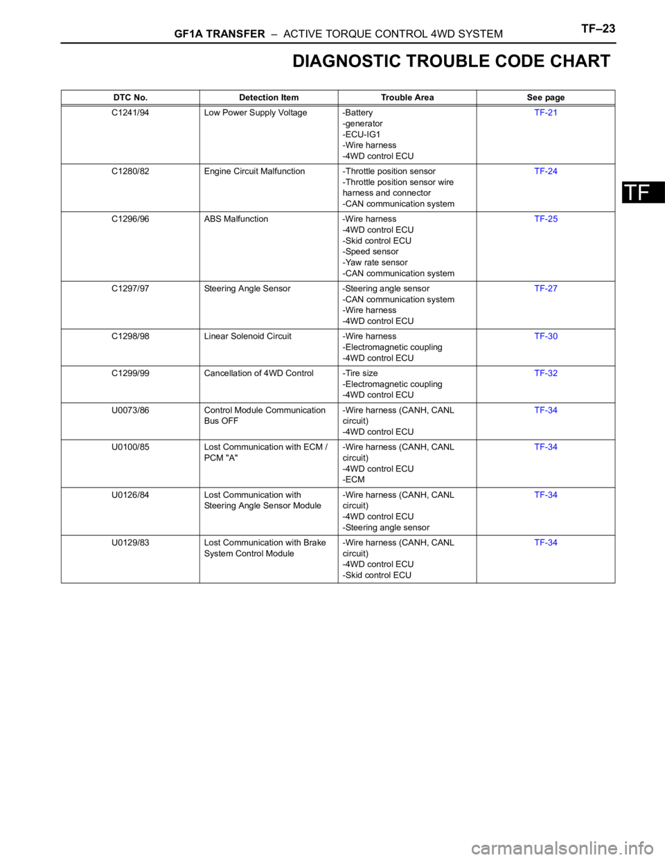
DIAGNOSTIC TROUBLE CODE CHART
DTC No. Detection Item Trouble Area See page
C1241/94 Low Power Supply Voltage -Battery
-generator
-ECU-IG1
-Wire harness
-4WD control ECUTF-21
C1280/82 Engine Circuit Malfunction -Throttle position sensor
-Throttle position sensor wire
harness and connector
-CAN communication systemTF-24
C1296/96 ABS Malfunction -Wire harness
-4WD control ECU
-Skid control ECU
-Speed sensor
-Yaw rate sensor
-CAN communication systemTF-25
C1297/97 Steering Angle Sensor -Steering angle sensor
-CAN communication system
-Wire harness
-4WD control ECUTF-27
C1298/98 Linear Solenoid Circuit -Wire harness
-Electromagnetic coupling
-4WD control ECUTF-30
C1299/99 Cancellation of 4WD Control -Tire size
-Electromagnetic coupling
-4WD control ECUTF-32
U0073/86 Control Module Communication
Bus OFF-Wire harness (CANH, CANL
circuit)
-4WD control ECUTF-34
U0100/85 Lost Communication with ECM /
PCM "A"-Wire harness (CANH, CANL
circuit)
-4WD control ECU
-ECMTF-34
U0126/84 Lost Communication with
Steering Angle Sensor Module-Wire harness (CANH, CANL
circuit)
-4WD control ECU
-Steering angle sensorTF-34
U0129/83 Lost Communication with Brake
System Control Module-Wire harness (CANH, CANL
circuit)
-4WD control ECU
-Skid control ECUTF-34
Page 1356 of 2000

TF–28GF1A TRANSFER – ACTIVE TORQUE CONTROL 4WD SYSTEM
TF
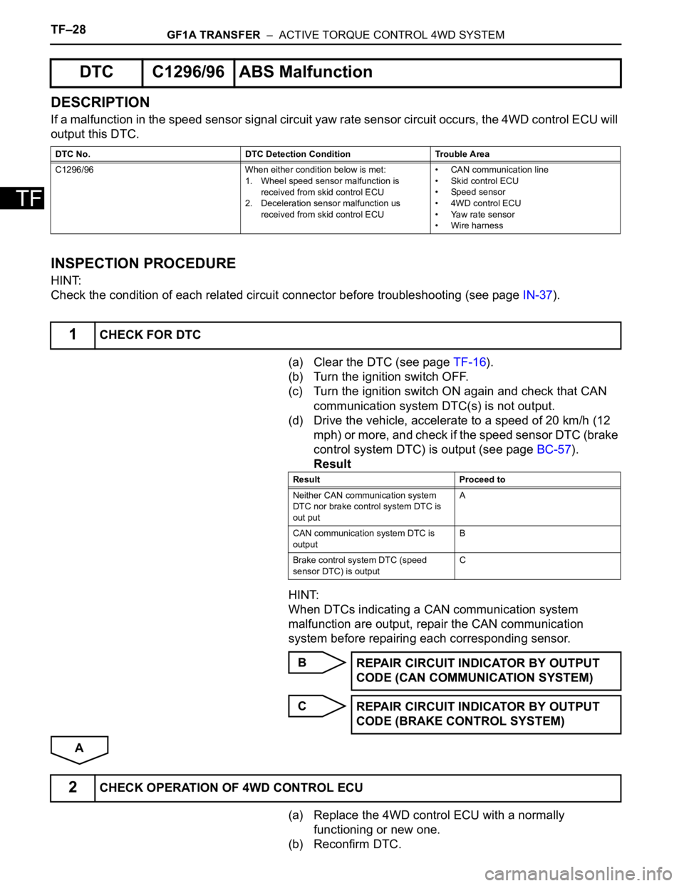
DESCRIPTION
If a malfunction in the speed sensor signal circuit yaw rate sensor circuit occurs, the 4WD control ECU will
output this DTC.
INSPECTION PROCEDURE
HINT:
Check the condition of each related circuit connector before troubleshooting (see page IN-37).
(a) Clear the DTC (see page TF-16).
(b) Turn the ignition switch OFF.
(c) Turn the ignition switch ON again and check that CAN
communication system DTC(s) is not output.
(d) Drive the vehicle, accelerate to a speed of 20 km/h (12
mph) or more, and check if the speed sensor DTC (brake
control system DTC) is output (see page BC-57).
Result
HINT:
When DTCs indicating a CAN communication system
malfunction are output, repair the CAN communication
system before repairing each corresponding sensor.
B
C
A
(a) Replace the 4WD control ECU with a normally
functioning or new one.
(b) Reconfirm DTC.
DTC C1296/96 ABS Malfunction
DTC No. DTC Detection Condition Trouble Area
C1296/96 When either condition below is met:
1. Wheel speed sensor malfunction is
received from skid control ECU
2. Deceleration sensor malfunction us
received from skid control ECU• CAN communication line
• Skid control ECU
• Speed sensor
• 4WD control ECU
• Yaw rate sensor
• Wire harness
1CHECK FOR DTC
Result Proceed to
Neither CAN communication system
DTC nor brake control system DTC is
out putA
CAN communication system DTC is
outputB
Brake control system DTC (speed
sensor DTC) is outputC
REPAIR CIRCUIT INDICATOR BY OUTPUT
CODE (CAN COMMUNICATION SYSTEM)
REPAIR CIRCUIT INDICATOR BY OUTPUT
CODE (BRAKE CONTROL SYSTEM)
2CHECK OPERATION OF 4WD CONTROL ECU
Page 1451 of 2000

AH–10AXLE – FRONT AXLE HUB
AH
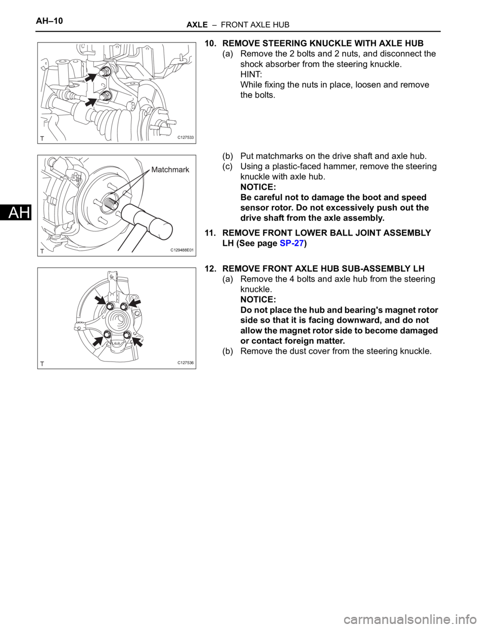
10. REMOVE STEERING KNUCKLE WITH AXLE HUB
(a) Remove the 2 bolts and 2 nuts, and disconnect the
shock absorber from the steering knuckle.
HINT:
While fixing the nuts in place, loosen and remove
the bolts.
(b) Put matchmarks on the drive shaft and axle hub.
(c) Using a plastic-faced hammer, remove the steering
knuckle with axle hub.
NOTICE:
Be careful not to damage the boot and speed
sensor rotor. Do not excessively push out the
drive shaft from the axle assembly.
11. REMOVE FRONT LOWER BALL JOINT ASSEMBLY
LH (See page SP-27)
12. REMOVE FRONT AXLE HUB SUB-ASSEMBLY LH
(a) Remove the 4 bolts and axle hub from the steering
knuckle.
NOTICE:
Do not place the hub and bearing's magnet rotor
side so that it is facing downward, and do not
allow the magnet rotor side to become damaged
or contact foreign matter.
(b) Remove the dust cover from the steering knuckle.
C127533
C129488E01
C127536