2006 TOYOTA RAV4 abs sensor
[x] Cancel search: abs sensorPage 1539 of 2000
BC–36BRAKE CONTROL – VEHICLE STABILITY CONTROL SYSTEM
BC
(4) Check that the brake warning light goes off when
quickly releasing the brake pedal. (The lost
booster pressure state is judged normal.)
(5) Leave the vehicle for 1 second or more. (Master
cylinder pressure sensor zero point calibration.)
NOTICE:
• If you slowly depress the brake pedal or
depress it again, master cylinder pressure
sensor zero point calibration is not
performed normally.
• If the lost booster pressure judgment
check is not completed normally, the
master cylinder pressure sensor check is
not judged.
• If a recheck is performed after the engine
has started, end the Test Mode, enter Test
Mode again, and release the vacuum in
the booster by pumping the brake pedal
prior to the recheck.
(c) Check the deceleration sensor.
(1) Keep the vehicle stationary on a level surface for
1 second or more.
HINT:
The deceleration sensor check can be
performed together with the following master
cylinder pressure sensor check.
(d) Check the master cylinder pressure sensor.
(1) Leave the vehicle in a stationary condition and
release the brake pedal for 1 second or more,
and quickly depress the brake pedal with a force
of 98 N (10 kgf, 22 lbf) or more for 1 second.
Check that the ABS warning light remains
illuminated for 3 seconds.
HINT:
• Ensure that the ABS warning light comes on.
• While the ABS warning light remains
illuminated, continue depressing the brake
pedal with a force of 98 N (10 kgf, 22 lbf) or
more.
• The ABS warning light comes on for 3
seconds every time the brake pedal operation
above is performed.
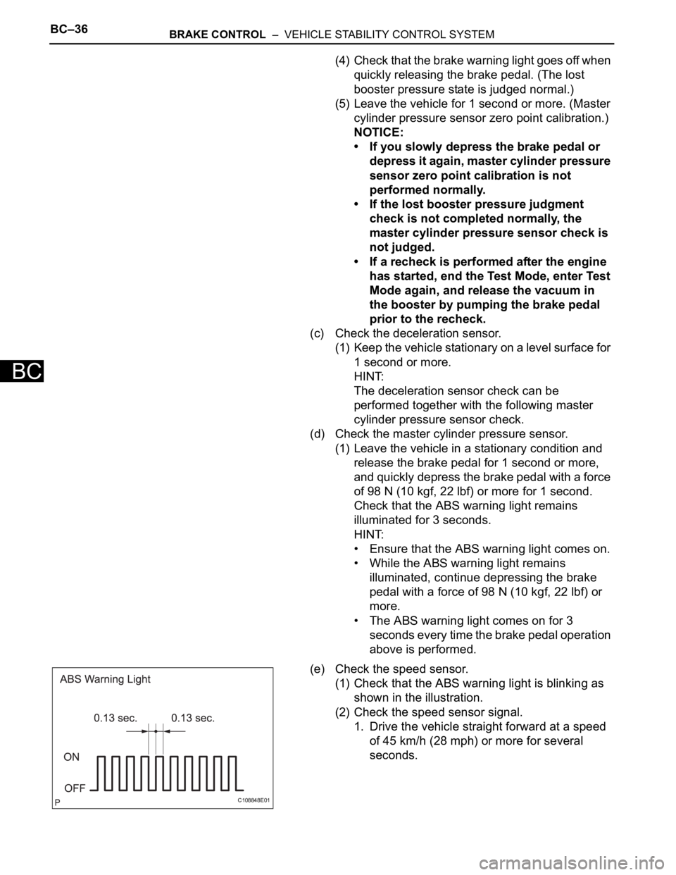
(e) Check the speed sensor.
(1) Check that the ABS warning light is blinking as
shown in the illustration.
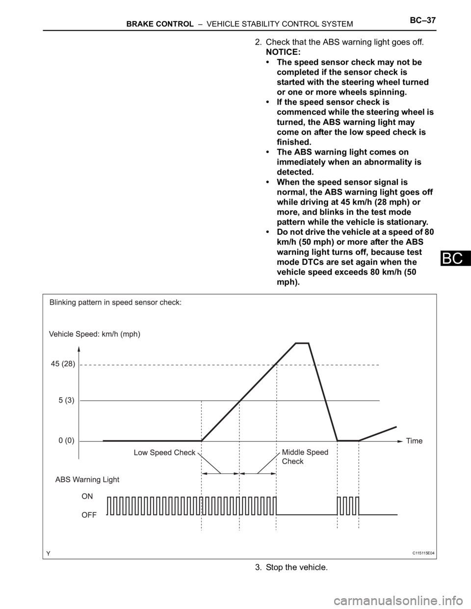
(2) Check the speed sensor signal.
1. Drive the vehicle straight forward at a speed
of 45 km/h (28 mph) or more for several
seconds.
C108848E01
Page 1540 of 2000
BRAKE CONTROL – VEHICLE STABILITY CONTROL SYSTEMBC–37
BC
2. Check that the ABS warning light goes off.
NOTICE:
• The speed sensor check may not be
completed if the sensor check is
started with the steering wheel turned
or one or more wheels spinning.
• If the speed sensor check is
commenced while the steering wheel is
turned, the ABS warning light may
come on after the low speed check is
finished.
• The ABS warning light comes on
immediately when an abnormality is
detected.
• When the speed sensor signal is
normal, the ABS warning light goes off
while driving at 45 km/h (28 mph) or
more, and blinks in the test mode
pattern while the vehicle is stationary.
• Do not drive the vehicle at a speed of 80
km/h (50 mph) or more after the ABS
warning light turns off, because test
mode DTCs are set again when the
vehicle speed exceeds 80 km/h (50
mph).
3. Stop the vehicle.
C115115E04
Page 1542 of 2000
BRAKE CONTROL – VEHICLE STABILITY CONTROL SYSTEMBC–39
BC
(h) w/ Auto LSD only:
Check the end of the sensor.
(1) When the sensor check is successfully
completed, the ABS warning light blinks in the
test mode pattern when the vehicle is stopped,
and goes off when the vehicle is driven.
NOTICE:
If the sensor check is not completed, the
ABS warning light blinks even while the
vehicle is driving and the ABS does not
operate.
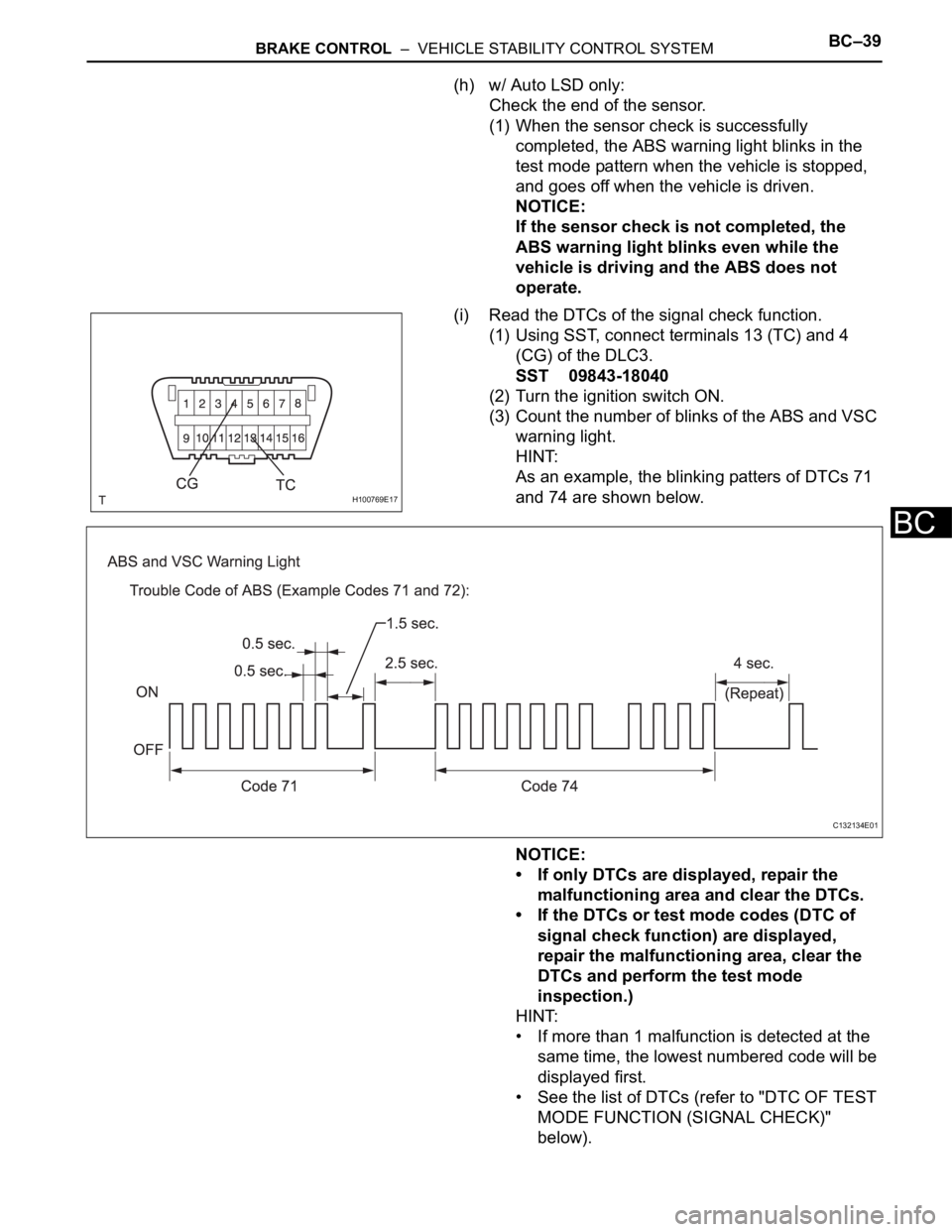
(i) Read the DTCs of the signal check function.
(1) Using SST, connect terminals 13 (TC) and 4
(CG) of the DLC3.
SST 09843-18040
(2) Turn the ignition switch ON.
(3) Count the number of blinks of the ABS and VSC
warning light.
HINT:
As an example, the blinking patters of DTCs 71
and 74 are shown below.
NOTICE:
• If only DTCs are displayed, repair the
malfunctioning area and clear the DTCs.
• If the DTCs or test mode codes (DTC of
signal check function) are displayed,
repair the malfunctioning area, clear the
DTCs and perform the test mode
inspection.)
HINT:
• If more than 1 malfunction is detected at the
same time, the lowest numbered code will be
displayed first.
• See the list of DTCs (refer to "DTC OF TEST
MODE FUNCTION (SIGNAL CHECK)"
below).
H100769E17
C132134E01
Page 1543 of 2000
BC–40BRAKE CONTROL – VEHICLE STABILITY CONTROL SYSTEM
BC
• If all sensors are normal, a normal system
code is output (the light comes on for 0.25
seconds at intervals of 0.25 seconds).
(4) After the check, disconnect SST from terminals
13 (TC) and 4 (CG) of the DLC3.
(5) Turn the ignition switch OFF.
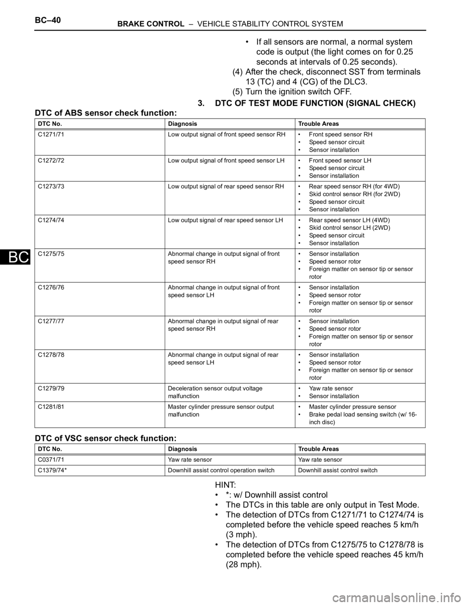
3. DTC OF TEST MODE FUNCTION (SIGNAL CHECK)
DTC of ABS sensor check function:
DTC of VSC sensor check function:
HINT:
• *: w/ Downhill assist control
• The DTCs in this table are only output in Test Mode.
• The detection of DTCs from C1271/71 to C1274/74 is
completed before the vehicle speed reaches 5 km/h
(3 mph).
• The detection of DTCs from C1275/75 to C1278/78 is
completed before the vehicle speed reaches 45 km/h
(28 mph).
DTC No. Diagnosis Trouble Areas
C1271/71 Low output signal of front speed sensor RH • Front speed sensor RH
• Speed sensor circuit
• Sensor installation
C1272/72 Low output signal of front speed sensor LH • Front speed sensor LH
• Speed sensor circuit
• Sensor installation
C1273/73 Low output signal of rear speed sensor RH • Rear speed sensor RH (for 4WD)
• Skid control sensor RH (for 2WD)
• Speed sensor circuit
• Sensor installation
C1274/74 Low output signal of rear speed sensor LH • Rear speed sensor LH (4WD)
• Skid control sensor LH (2WD)
• Speed sensor circuit
• Sensor installation
C1275/75 Abnormal change in output signal of front
speed sensor RH• Sensor installation
• Speed sensor rotor
• Foreign matter on sensor tip or sensor
rotor
C1276/76 Abnormal change in output signal of front
speed sensor LH• Sensor installation
• Speed sensor rotor
• Foreign matter on sensor tip or sensor
rotor
C1277/77 Abnormal change in output signal of rear
speed sensor RH• Sensor installation
• Speed sensor rotor
• Foreign matter on sensor tip or sensor
rotor
C1278/78 Abnormal change in output signal of rear
speed sensor LH• Sensor installation
• Speed sensor rotor
• Foreign matter on sensor tip or sensor
rotor
C1279/79 Deceleration sensor output voltage
malfunction• Yaw rate sensor
• Sensor installation
C1281/81 Master cylinder pressure sensor output
malfunction• Master cylinder pressure sensor
• Brake pedal load sensing switch (w/ 16-
inch disc)
DTC No. Diagnosis Trouble Areas
C0371/71 Yaw rate sensor Yaw rate sensor
C1379/74* Downhill assist control operation switch Downhill assist control switch
Page 1545 of 2000
BC–42BRAKE CONTROL – VEHICLE STABILITY CONTROL SYSTEM
BC
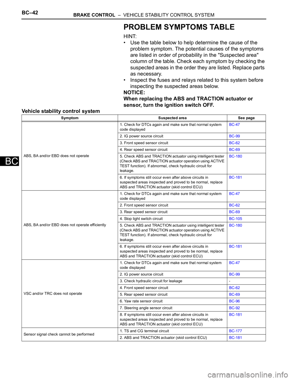
PROBLEM SYMPTOMS TABLE
HINT:
• Use the table below to help determine the cause of the
problem symptom. The potential causes of the symptoms
are listed in order of probability in the "Suspected area"
column of the table. Check each symptom by checking the
suspected areas in the order they are listed. Replace parts
as necessary.
• Inspect the fuses and relays related to this system before
inspecting the suspected areas below.
NOTICE:
When replacing the ABS and TRACTION actuator or
sensor, turn the ignition switch OFF.
Vehicle stability control system
Symptom Suspected area See page
ABS, BA and/or EBD does not operate1. Check for DTCs again and make sure that normal system
code displayedBC-47
2. IG power source circuitBC-99
3. Front speed sensor circuitBC-62
4. Rear speed sensor circuitBC-69
5. Check ABS and TRACTION actuator using intelligent tester
(Check ABS and TRACTION actuator operation using ACTIVE
TEST function). If abnormal, check hydraulic circuit for
leakage.BC-180
6. If symptoms still occur even after above circuits in
suspected areas inspected and proved to be normal, replace
ABS and TRACTION actuator (skid control ECU)BC-181
ABS, BA and/or EBD does not operate efficiently1. Check for DTCs again and make sure that normal system
code displayedBC-47
2. Front speed sensor circuitBC-62
3. Rear speed sensor circuitBC-69
4. Stop light switch circuitBC-105
5. Check ABS and TRACTION actuator using intelligent tester
(Check ABS and TRACTION actuator operation using ACTIVE
TEST function). If abnormal, check hydraulic circuit for
leakage.BC-180
6. If symptoms still occur even after above circuits in
suspected areas inspected and proved to be normal, replace
ABS and TRACTION actuator (skid control ECU)BC-181
VSC and/or TRC does not operate1. Check for DTCs again and make sure that normal system
code displayedBC-47
2. IG power source circuitBC-99
3. Check hydraulic circuit for leakage -
4. Front speed sensor circuitBC-62
5. Rear speed sensor circuitBC-69
6. Yaw rate sensor circuitBC-96
7. Steering angle sensor circuitBC-92
8. If symptoms still occur even after above circuits in
suspected areas inspected and proved to be normal, replace
ABS and TRACTION actuator (skid control ECU)BC-181
Sensor signal check cannot be performed1. TS and CG terminal circuitBC-177
2. ABS and TRACTION actuator (skid control ECU)BC-181
Page 1552 of 2000
BRAKE CONTROL – VEHICLE STABILITY CONTROL SYSTEMBC–49
BC
• *4: w/ 16-inch disc
• The DTCs can be read by connecting SST (09843-
18040) between the TC and CG terminals of the
DLC3 and observing the blinking pattern of the ABS
and VSC warning lights, or by using an intelligent
tester (see page BC-47).
• This system has a sensor signal check function (see
page BC-28).
2. CHECK WARNING LIGHT AND INDICATOR LIGHT
(a) Release the parking brake lever.
NOTICE:
Before releasing the parking brake lever, set
chocks to hold the vehicle for safety.
HINT:
When the parking brake is applied or the brake fluid
level is low, the brake warning light comes on.
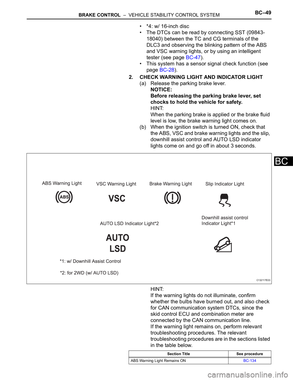
(b) When the ignition switch is turned ON, check that
the ABS, VSC and brake warning lights and the slip,
downhill assist control and AUTO LSD indicator
lights come on and go off in about 3 seconds.
HINT:
If the warning lights do not illuminate, confirm
whether the bulbs have burned out, and also check
for CAN communication system DTCs, since the
skid control ECU and combination meter are
connected by the CAN communication line.
If the warning light remains on, perform relevant
troubleshooting procedures. The relevant
troubleshooting procedures are in the sections listed
in the table below.
C132117E03
Section Title See procedure
ABS Warning Light Remains ONBC-134
Page 1556 of 2000

BRAKE CONTROL – VEHICLE STABILITY CONTROL SYSTEMBC–53
BC
FREEZE FRAME DATA
1. FREEZE FRAME DATA
HINT:
• Whenever a DTC is detected or the ABS operates,
the skid control ECU stores the current vehicle
(sensor) state as freeze frame data.
• The skid control ECU stores the number of times
(maximum: 31) the ignition switch has been turned
from OFF to ON since the last time the ABS was
activated. However, if the vehicle was stationary or
running at a low speed (7 km/h [4.3 mph] or less), or if
a DTC is detected, the skid control ECU stops
counting.
• Freeze frame data at the time the ABS operates:
The skid control ECU stores and updates the data
whenever the ABS system operates.
When the ECU stores data at the time a DTC is
detected, the data stored when the ABS operated is
erased.
• Freeze frame data at the time a DTC is detected:
When the skid control ECU stores data at the time a
DTC is detected, no updates will be performed until
the data is cleared.
(a) Connect the intelligent tester (with CAN VIM) to the
DLC3.
(b) Turn the ignition switch ON.
(c) Turn the tester on.
(d) From the display on the tester, select "FREEZE
FRAME DATA".
B127989E01
Item (Display) Measurement Item Reference Values
FREEZE TIME Elapsed time after freeze frame data recorded Min.: 0 ms
Max.: 500 ms
#IG ON Number of ignition switch ON operations since
freeze frame data stored1 to 31
BUZZER Skid control buzzer signal ON: Skid control buzzer ON
OFF: Skid control buzzer OFF
STOP LAMP SW Stop light switch signal ON: Stop light switch ON
OFF: Stop light switch OFF
PARKING BRAKE SW Parking brake switch signal ON: Parking brake switch ON
OFF: Parking brake switch OFF
BRK PEDAL SW Brake pedal load sensing switch signal ON: Brake pedal released
OFF: Brake pedal depressed
Page 1557 of 2000
BC–54BRAKE CONTROL – VEHICLE STABILITY CONTROL SYSTEM
BC
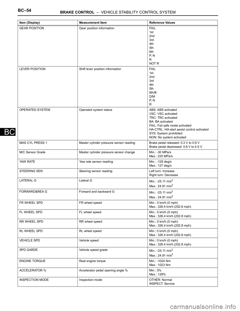
GEAR POSITION Gear position information FAIL
1st
2nd
3rd
4th
5th
6th
P, N
R
NOT R
LEVER POSITION Shift lever position information FAIL
1st
2nd
3rd
4th
5th
6th/B
D/M
P, N
R
OPERATED SYSTEM Operated system status ABS: ABS activated
VSC: VSC activated
TRC: TRC activated
BA: BA activated
FAIL: Fail safe mode activated
HA-CTRL: Hill-start assist control activated
SYS: System prohibited
NON: No system activated
MAS CYL PRESS 1 Master cylinder pressure sensor reading Brake pedal released: 0.3 V to 0.9 V
Brake pedal depressed: 0.8 V to 4.5 V
M/C Sensor Grade Master cylinder pressure sensor change Min.: -30 MPa/s
Max.: 225 MPa/s
YAW RATE Yaw rate sensor reading Min.: -128 deg/s
Max.: 127 deg/s
STEERING SEN Steering sensor reading Left turn: Increase
Right turn: Decrease
LATERAL G Lateral G
Min.: -25.11 m/s
2
Max.: 24.91 m/s2
FORWARD&REA G Forward and backward G
Min.: -25.11 m/s2
Max.: 24.91 m/s2
FR WHEEL SPD FR wheel speed Min.: 0 km/h (0 mph)
Max.: 326.4 km/h (202.8 mph)
FL WHEEL SPD FL wheel speed Min.: 0 km/h (0 mph)
Max.: 326.4 km/h (202.8 mph)
RR WHEEL SPD RR wheel speed Min.: 0 km/h (0 mph)
Max.: 326.4 km/h (202.8 mph)
RL WHEEL SPD RL wheel speed Min.: 0 km/h (0 mph)
Max.: 326.4 km/h (202.8 mph)
VEHICLE SPD Vehicle speed Min.: 0 km/h (0 mph)
Max.: 326.4 km/h (202.8 mph)
SPD GARDE Vehicle speed grade
Min.: -25.11 m/s
2
Max.: 24.91 m/s2
ENGINE TORQUE Real engine torque Min.: -1024 Nm
Max.: 1023 Nm
ACCELERATOR % Accelerator pedal opening angle % Min.: 0%
Max.: 128%
INSPECTION MODE Inspection mode OTHER: Normal
INSPECT: Service Item (Display) Measurement Item Reference Values