2006 TOYOTA RAV4 low beam
[x] Cancel search: low beamPage 167 of 2000
IN–22INTRODUCTION – REPAIR INSTRUCTION
IN
VEHICLE LIFT AND SUPPORT
LOCATIONS
1. NOTICE ABOUT VEHICLE CONDITION WHEN
JACKING UP VEHICLE
(a) The vehicle must be unloaded before jacking up /
lifting up the vehicle. Never jack up / lift up a heavily
loaded vehicle.
(b) When removing heavy parts such as the engine and
transmission, the center of gravity of the vehicle
may shift. To stabilize the vehicle, place a balance
weight in a location where it will not roll or shift, or
use a mission jack to hold the jacking support.
2. NOTICE FOR USING 4 POST LIFT
(a) Follow the safety procedures outlined in the lift
instruction manual.
(b) Use precautionary measures to prevent the free
wheel beam from damaging tires or wheels.
(c) Use wheel chocks to secure the vehicle.
3. NOTICE FOR USING JACK AND SAFETY STAND
(a) Work on a level surface. Use wheel chocks at all
times.
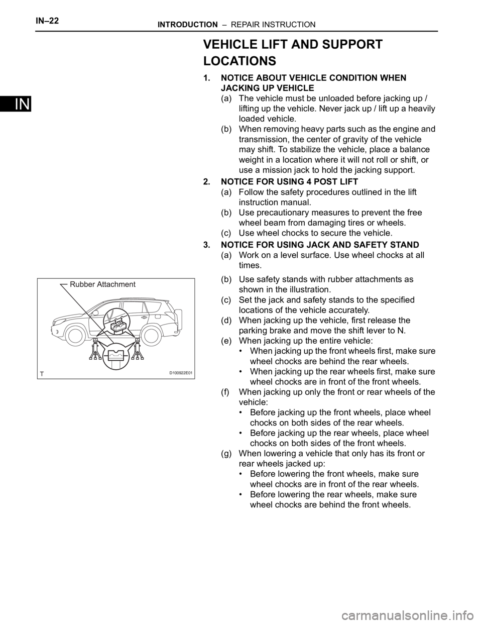
(b) Use safety stands with rubber attachments as
shown in the illustration.
(c) Set the jack and safety stands to the specified
locations of the vehicle accurately.
(d) When jacking up the vehicle, first release the
parking brake and move the shift lever to N.
(e) When jacking up the entire vehicle:
• When jacking up the front wheels first, make sure
wheel chocks are behind the rear wheels.
• When jacking up the rear wheels first, make sure
wheel chocks are in front of the front wheels.
(f) When jacking up only the front or rear wheels of the
vehicle:
• Before jacking up the front wheels, place wheel
chocks on both sides of the rear wheels.
• Before jacking up the rear wheels, place wheel
chocks on both sides of the front wheels.
(g) When lowering a vehicle that only has its front or
rear wheels jacked up:
• Before lowering the front wheels, make sure
wheel chocks are in front of the rear wheels.
• Before lowering the rear wheels, make sure
wheel chocks are behind the front wheels.
D100922E01
Page 341 of 2000

CH–62AZ-FE CHARGING – CHARGING SYSTEM
CH
8. INSPECT CHARGING CIRCUIT WITH LOAD
(a) With the engine running at 2,000 rpm, turn the high
beam headlights ON and turn the heater blower
switch to the "HI" position.
(b) Check the reading on the ammeter.
Standard amperage:
30 A or more
If the ammeter reading is less than the standard
amperage, repair the generator.
HINT:
If the battery is fully charged, the indication will
sometimes be less than the standard amperage. If
this is the case, add more electrical load (operate
the wipers, rear window defogger, etc.) and check
the reading on the ammeter again.
Page 930 of 2000

2GR-FE CHARGING – CHARGING SYSTEMCH–7
CH
8. INSPECT CHARGING CIRCUIT WITH LOAD
(a) With the engine running at 2,000 rpm, turn the high
beam headlights ON and turn the heater blower
switch to the "HI" position.
(b) Check the reading on the ammeter.
Standard amperage:
30 A or more
If the ammeter reading is less than the standard
amperage, repair the generator.
HINT:
If the battery is fully charged, the indication will
sometimes be less than the standard amperage.
If this is the case, add more electrical load (operate
the wipers, rear window defogger, etc.) and check
the reading on the ammeter again.
Page 1840 of 2000

LIGHTING – LIGHTING SYSTEMLI–9
LI
(3) The main body ECU controls the illumination
period of the following parts based on the
signals listed in G.
• Headlight (LOW)
• Headlight (HIGH)
• Side marker light (front and rear)
• Front fog light
(e) Daytime running light system:
This system is directly connected to the high-beam
headlights and is designed to automatically activate
the daytime running lights in order to increase the
visibility of the vehicle.
(1) The main body ECU receives the following (H).
• Ignition switch signal
• Engine speed
• Parking brake switch signal
• Light control switch signal
(2) The main body ECU controls the following signal
based on the signals listed in H (I).
• Daytime running light No. 2 relay operation
signal
(3) The main body ECU controls the on/off
operation of the following part based on the
signal listed in I.
• Headlight (HIGH)
Page 1846 of 2000
LIGHTING – LIGHTING SYSTEMLI–15
LI
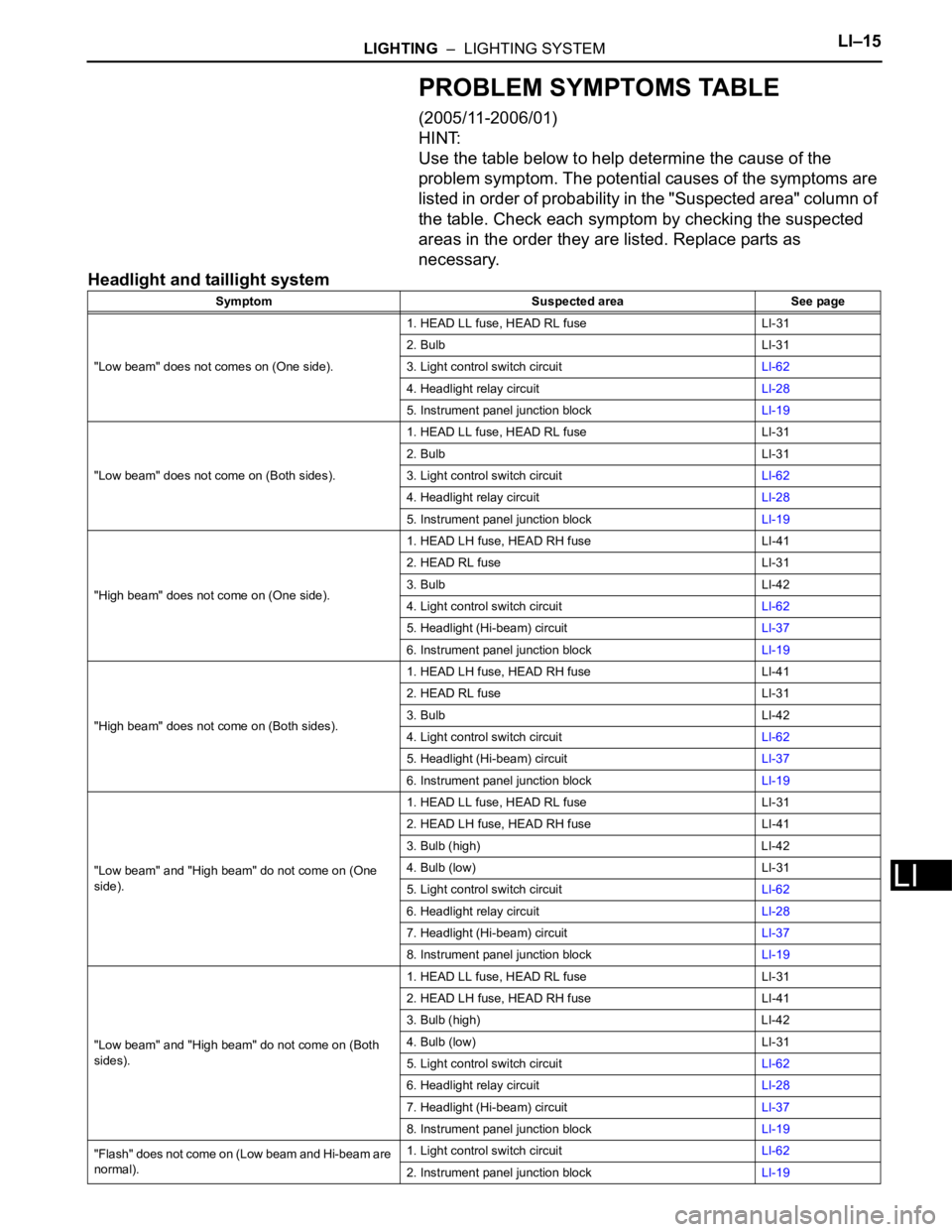
PROBLEM SYMPTOMS TABLE
(2005/11-2006/01)
HINT:
Use the table below to help determine the cause of the
problem symptom. The potential causes of the symptoms are
listed in order of probability in the "Suspected area" column of
the table. Check each symptom by checking the suspected
areas in the order they are listed. Replace parts as
necessary.
Headlight and taillight system
Symptom Suspected area See page
"Low beam" does not comes on (One side).1. HEAD LL fuse, HEAD RL fuse LI-31
2. Bulb LI-31
3. Light control switch circuitLI-62
4. Headlight relay circuitLI-28
5. Instrument panel junction blockLI-19
"Low beam" does not come on (Both sides).1. HEAD LL fuse, HEAD RL fuse LI-31
2. Bulb LI-31
3. Light control switch circuitLI-62
4. Headlight relay circuitLI-28
5. Instrument panel junction blockLI-19
"High beam" does not come on (One side).1. HEAD LH fuse, HEAD RH fuse LI-41
2. HEAD RL fuse LI-31
3. Bulb LI-42
4. Light control switch circuitLI-62
5. Headlight (Hi-beam) circuitLI-37
6. Instrument panel junction blockLI-19
"High beam" does not come on (Both sides).1. HEAD LH fuse, HEAD RH fuse LI-41
2. HEAD RL fuse LI-31
3. Bulb LI-42
4. Light control switch circuitLI-62
5. Headlight (Hi-beam) circuitLI-37
6. Instrument panel junction blockLI-19
"Low beam" and "High beam" do not come on (One
side).1. HEAD LL fuse, HEAD RL fuse LI-31
2. HEAD LH fuse, HEAD RH fuse LI-41
3. Bulb (high) LI-42
4. Bulb (low) LI-31
5. Light control switch circuitLI-62
6. Headlight relay circuitLI-28
7. Headlight (Hi-beam) circuitLI-37
8. Instrument panel junction blockLI-19
"Low beam" and "High beam" do not come on (Both
sides).1. HEAD LL fuse, HEAD RL fuse LI-31
2. HEAD LH fuse, HEAD RH fuse LI-41
3. Bulb (high) LI-42
4. Bulb (low) LI-31
5. Light control switch circuitLI-62
6. Headlight relay circuitLI-28
7. Headlight (Hi-beam) circuitLI-37
8. Instrument panel junction blockLI-19
"Flash" does not come on (Low beam and Hi-beam are
normal).1. Light control switch circuitLI-62
2. Instrument panel junction blockLI-19
Page 1849 of 2000
LI–18LIGHTING – LIGHTING SYSTEM
LI
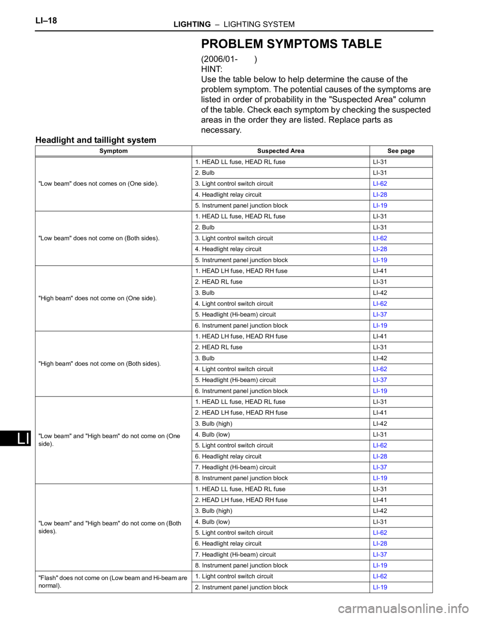
PROBLEM SYMPTOMS TABLE
(2006/01- )
HINT:
Use the table below to help determine the cause of the
problem symptom. The potential causes of the symptoms are
listed in order of probability in the "Suspected Area" column
of the table. Check each symptom by checking the suspected
areas in the order they are listed. Replace parts as
necessary.
Headlight and taillight system
Symptom Suspected Area See page
"Low beam" does not comes on (One side).1. HEAD LL fuse, HEAD RL fuse LI-31
2. Bulb LI-31
3. Light control switch circuitLI-62
4. Headlight relay circuitLI-28
5. Instrument panel junction blockLI-19
"Low beam" does not come on (Both sides).1. HEAD LL fuse, HEAD RL fuse LI-31
2. Bulb LI-31
3. Light control switch circuitLI-62
4. Headlight relay circuitLI-28
5. Instrument panel junction blockLI-19
"High beam" does not come on (One side).1. HEAD LH fuse, HEAD RH fuse LI-41
2. HEAD RL fuse LI-31
3. Bulb LI-42
4. Light control switch circuitLI-62
5. Headlight (Hi-beam) circuitLI-37
6. Instrument panel junction blockLI-19
"High beam" does not come on (Both sides).1. HEAD LH fuse, HEAD RH fuse LI-41
2. HEAD RL fuse LI-31
3. Bulb LI-42
4. Light control switch circuitLI-62
5. Headlight (Hi-beam) circuitLI-37
6. Instrument panel junction blockLI-19
"Low beam" and "High beam" do not come on (One
side).1. HEAD LL fuse, HEAD RL fuse LI-31
2. HEAD LH fuse, HEAD RH fuse LI-41
3. Bulb (high) LI-42
4. Bulb (low) LI-31
5. Light control switch circuitLI-62
6. Headlight relay circuitLI-28
7. Headlight (Hi-beam) circuitLI-37
8. Instrument panel junction blockLI-19
"Low beam" and "High beam" do not come on (Both
sides).1. HEAD LL fuse, HEAD RL fuse LI-31
2. HEAD LH fuse, HEAD RH fuse LI-41
3. Bulb (high) LI-42
4. Bulb (low) LI-31
5. Light control switch circuitLI-62
6. Headlight relay circuitLI-28
7. Headlight (Hi-beam) circuitLI-37
8. Instrument panel junction blockLI-19
"Flash" does not come on (Low beam and Hi-beam are
normal).1. Light control switch circuitLI-62
2. Instrument panel junction blockLI-19
Page 1853 of 2000
LI–22LIGHTING – LIGHTING SYSTEM
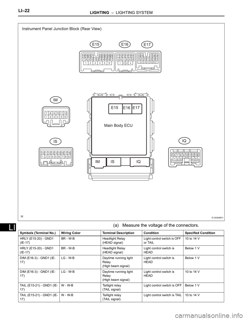
LI(a) Measure the voltage of the connectors.
E125304E01
Symbols (Terminal No.) Wiring Color Terminal Description ConditionSpecified Condition
HRLY (E15-20) - GND1
(IE-17)BR - W-B Headlight Relay
(HEAD signal)Light control switch is OFF
or TAIL10 to 14 V
HRLY (E15-20) - GND1
(IE-17)BR - W-B Headlight Relay
(HEAD signal)Light control switch is
HEADBelow 1 V
DIM (E16-3) - GND1 (IE-
17)LG - W-B Daytime running light
Relay
(High beam signal)Light control switch is
HEADBelow 1 V
DIM (E16-3) - GND1 (IE-
17)LG - W-B Daytime running light
Relay
(High beam signal)Light control switch is
HEAD10 to 14 V
TAIL (E15-21) - GND1 (IE-
17)W - W-B Taillight relay
(TAIL signal)Light control switch is OFF Below 1 V
TAIL (E15-21) - GND1 (IE-
17)W - W-B Taillight relay
(TAIL signal)Light control switch is TAIL 10 to 14 V
Page 1885 of 2000
LIGHTING – HEADLIGHT DIMMER SWITCHLI–135
LI
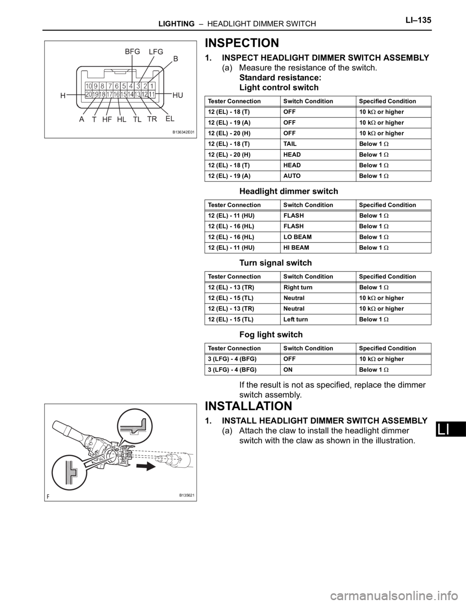
INSPECTION
1. INSPECT HEADLIGHT DIMMER SWITCH ASSEMBLY
(a) Measure the resistance of the switch.
Standard resistance:
Light control switch
Headlight dimmer switch
Turn signal switch
Fog light switch
If the result is not as specified, replace the dimmer
switch assembly.
INSTALLATION
1. INSTALL HEADLIGHT DIMMER SWITCH ASSEMBLY
(a) Attach the claw to install the headlight dimmer
switch with the claw as shown in the illustration.
B136342E01
Tester Connection Switch Condition Specified Condition
12 (EL) - 18 (T) OFF 10 k
or higher
12 (EL) - 19 (A) OFF 10 k
or higher
12 (EL) - 20 (H) OFF 10 k
or higher
12 (EL) - 18 (T) TAIL Below 1
12 (EL) - 20 (H) HEAD Below 1
12 (EL) - 18 (T) HEAD Below 1
12 (EL) - 19 (A) AUTO Below 1
Tester Connection Switch Condition Specified Condition
12 (EL) - 11 (HU) FLASH Below 1
12 (EL) - 16 (HL) FLASH Below 1
12 (EL) - 16 (HL) LO BEAM Below 1
12 (EL) - 11 (HU) HI BEAM Below 1
Tester Connection Switch Condition Specified Condition
12 (EL) - 13 (TR) Right turn Below 1
12 (EL) - 15 (TL) Neutral 10 k or higher
12 (EL) - 13 (TR) Neutral 10 k
or higher
12 (EL) - 15 (TL) Left turn Below 1
Tester Connection Switch Condition Specified Condition
3 (LFG) - 4 (BFG) OFF 10 k
or higher
3 (LFG) - 4 (BFG) ON Below 1
B135621