Page 69 of 2000
ENGINE - 2GR-FE ENGINE
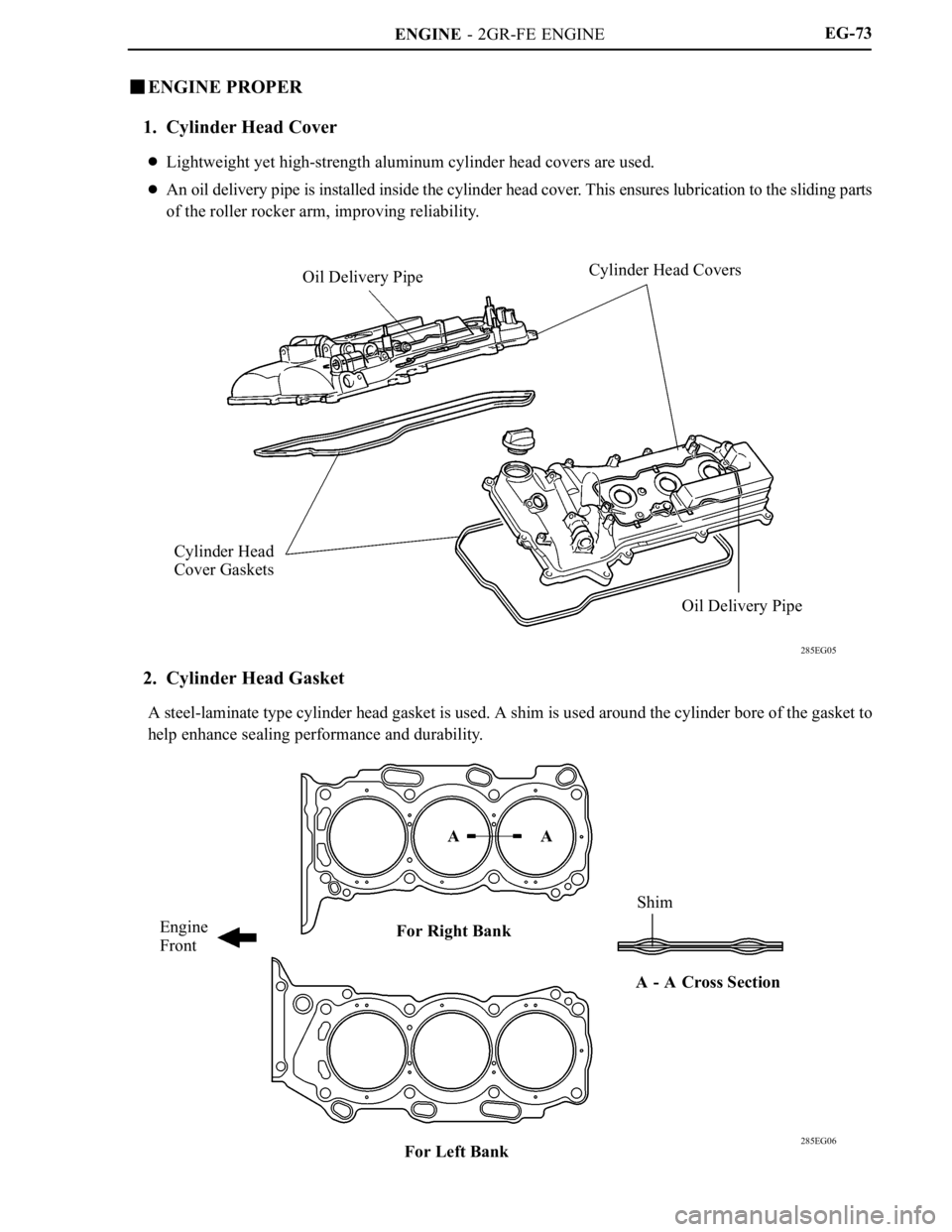
285EG05
Oil Delivery PipeCylinder Head Covers
Cylinder Head
Cover Gaskets
Oil Delivery Pipe
285EG06
Engine
FrontShim A A
For Right Bank
For Left BankA - A Cross SectionEG-73
ENGINE PROPER
1. Cylinder Head Cover
Lightweight yet high-strength aluminum cylinder head covers are used.
An oil delivery pipe is installed inside the cylinder head cover. This ensures lubrication to the sliding parts
of the roller rocker arm, improving reliability.
2. Cylinder Head Gasket
A steel-laminate type cylinder head gasket is used. A shim is used around the cylinder bore of the gasket to
help enhance sealing performance and durability.
Page 74 of 2000
ENGINE - 2GR-FE ENGINE
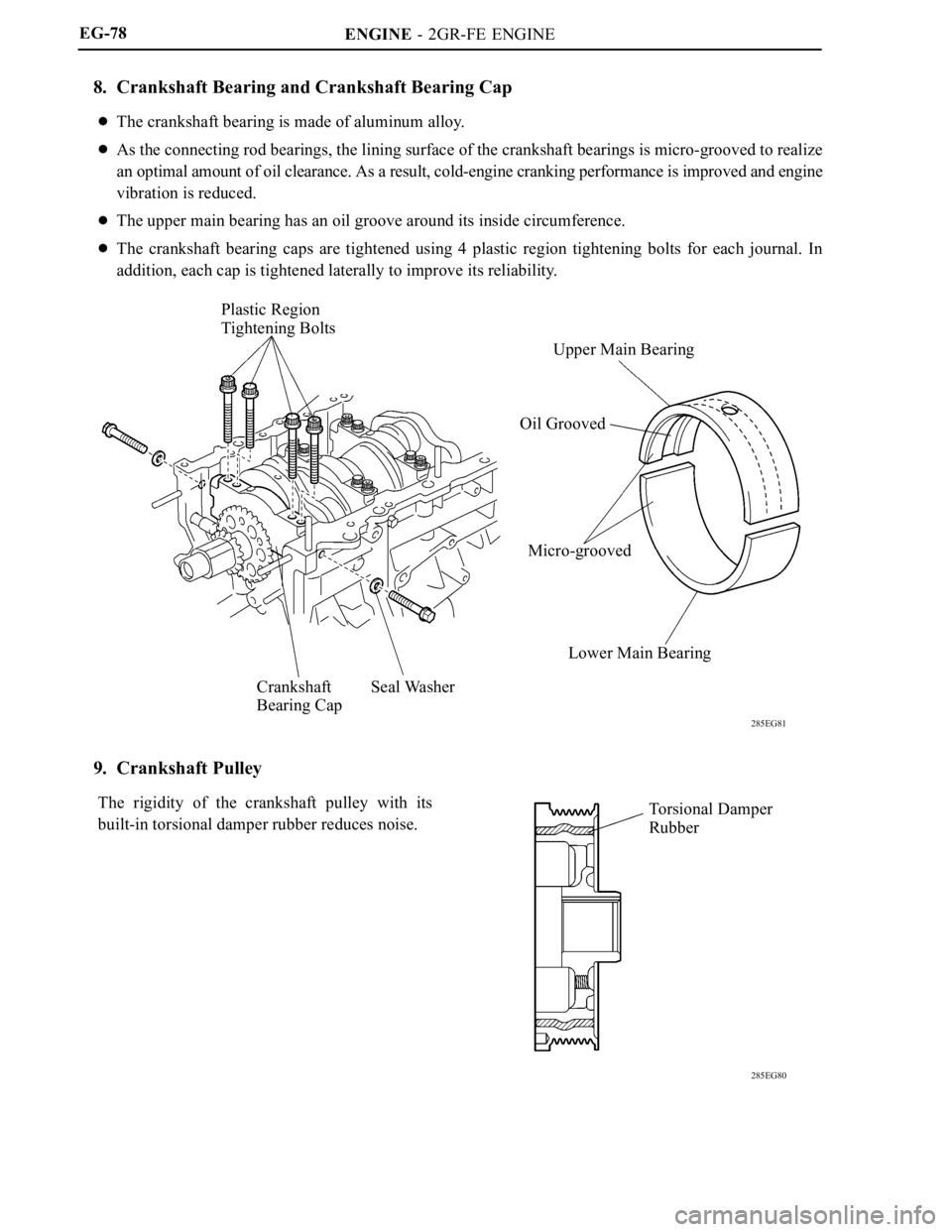
285EG81
Plastic Region
Tightening Bolts
Crankshaft
Bearing CapSeal WasherUpper Main Bearing
Oil Grooved
Micro-grooved
Lower Main Bearing
285EG80
Torsional Damper
Rubber EG-78
8. Crankshaft Bearing and Crankshaft Bearing Cap
The crankshaft bearing is made of aluminum alloy.
As the connecting rod bearings, the lining surface of the crankshaft bearings is micro-grooved to realize
an optimal amount of oil clearance. As a result, cold-engine cranking performance is improved and engine
vibration is reduced.
The upper main bearing has an oil groove around its inside circumference.
The crankshaft bearing caps are tightened using 4 plastic region tightening bolts for each journal. In
addition, each cap is tightened laterally to improve its reliability.
9. Crankshaft Pulley
The rigidity of the crankshaft pulley with its
built-in torsional damper rubber reduces noise.
Page 248 of 2000
2GR-FE LUBRICATION – OIL PUMPLU–13
LU
(b) Insert the blade of SST between the oil pan, cut
through the applied sealer and remove the oil pan.
SST 09032-00100
NOTICE:
Be careful not to damage the contact surfaces of
the oil pan.
10. REMOVE OIL STRAINER SUB-ASSEMBLY
(a) Remove the bolt, 2 nuts, oil strainer and gasket.
11. REMOVE OIL PAN SUB-ASSEMBLY
(a) Remove the 16 bolts and 2 nuts.
HINT:
Be sure to clean the bolts and stud bolts and check
the threads for cracks or other damage.
(b) Remove the oil pan by prying between the oil pan
and cylinder block with a screwdriver.
NOTICE:
Be careful not to damage the contact surfaces of
the cylinder block and oil pan.
HINT:
Tape the screwdriver tip before use.
A132161E01
A132108
A132109
A132110
Page 364 of 2000
AX–288U151F AUTOMATIC TRANSAXLE – DIFFERENTIAL CASE
AX
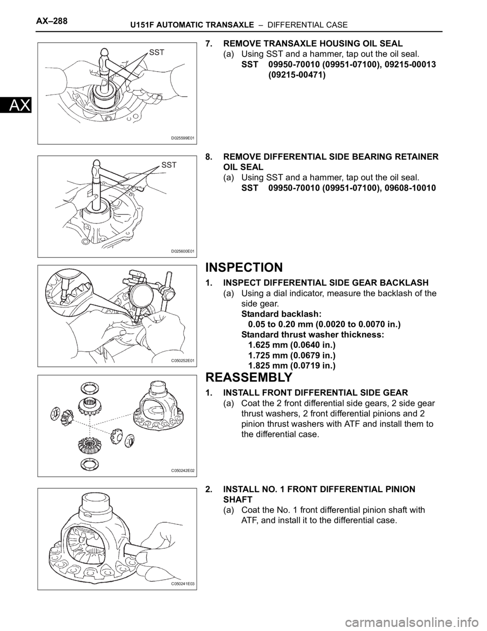
7. REMOVE TRANSAXLE HOUSING OIL SEAL
(a) Using SST and a hammer, tap out the oil seal.
SST 09950-70010 (09951-07100), 09215-00013
(09215-00471)
8. REMOVE DIFFERENTIAL SIDE BEARING RETAINER
OIL SEAL
(a) Using SST and a hammer, tap out the oil seal.
SST 09950-70010 (09951-07100), 09608-10010
INSPECTION
1. INSPECT DIFFERENTIAL SIDE GEAR BACKLASH
(a) Using a dial indicator, measure the backlash of the
side gear.
Standard backlash:
0.05 to 0.20 mm (0.0020 to 0.0070 in.)
Standard thrust washer thickness:
1.625 mm (0.0640 in.)
1.725 mm (0.0679 in.)
1.825 mm (0.0719 in.)
REASSEMBLY
1. INSTALL FRONT DIFFERENTIAL SIDE GEAR
(a) Coat the 2 front differential side gears, 2 side gear
thrust washers, 2 front differential pinions and 2
pinion thrust washers with ATF and install them to
the differential case.
2. INSTALL NO. 1 FRONT DIFFERENTIAL PINION
SHAFT
(a) Coat the No. 1 front differential pinion shaft with
ATF, and install it to the differential case.
D025599E01
D025600E01
C050252E01
C050242E02
C050241E03
Page 369 of 2000
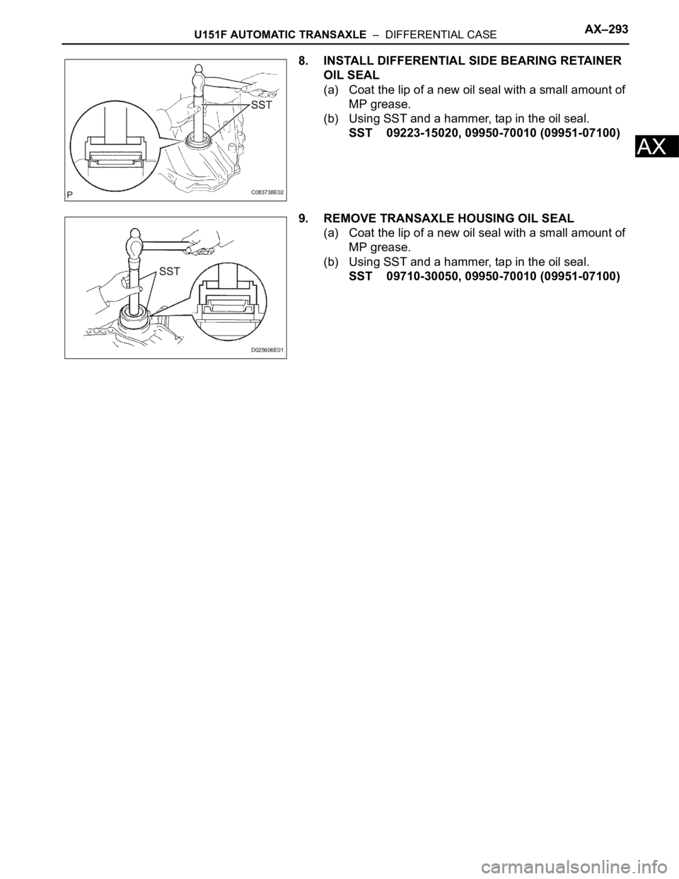
U151F AUTOMATIC TRANSAXLE – DIFFERENTIAL CASEAX–293
AX
8. INSTALL DIFFERENTIAL SIDE BEARING RETAINER
OIL SEAL
(a) Coat the lip of a new oil seal with a small amount of
MP grease.
(b) Using SST and a hammer, tap in the oil seal.
SST 09223-15020, 09950-70010 (09951-07100)
9. REMOVE TRANSAXLE HOUSING OIL SEAL
(a) Coat the lip of a new oil seal with a small amount of
MP grease.
(b) Using SST and a hammer, tap in the oil seal.
SST 09710-30050, 09950-70010 (09951-07100)
C083738E02
D025606E01
Page 376 of 2000
AX–248U241E AUTOMATIC TRANSAXLE – UNDERDRIVE CLUTCH
AX
INSPECTION
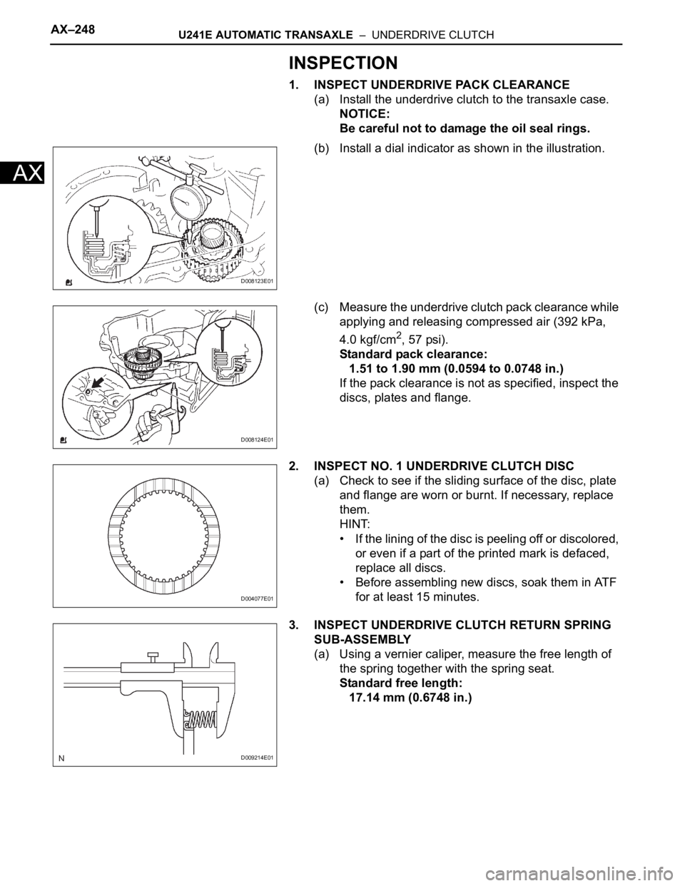
1. INSPECT UNDERDRIVE PACK CLEARANCE
(a) Install the underdrive clutch to the transaxle case.
NOTICE:
Be careful not to damage the oil seal rings.
(b) Install a dial indicator as shown in the illustration.
(c) Measure the underdrive clutch pack clearance while
applying and releasing compressed air (392 kPa,
4.0 kgf/cm
2, 57 psi).
Standard pack clearance:
1.51 to 1.90 mm (0.0594 to 0.0748 in.)
If the pack clearance is not as specified, inspect the
discs, plates and flange.
2. INSPECT NO. 1 UNDERDRIVE CLUTCH DISC
(a) Check to see if the sliding surface of the disc, plate
and flange are worn or burnt. If necessary, replace
them.
HINT:
• If the lining of the disc is peeling off or discolored,
or even if a part of the printed mark is defaced,
replace all discs.
• Before assembling new discs, soak them in ATF
for at least 15 minutes.
3. INSPECT UNDERDRIVE CLUTCH RETURN SPRING
SUB-ASSEMBLY
(a) Using a vernier caliper, measure the free length of
the spring together with the spring seat.
Standard free length:
17.14 mm (0.6748 in.)
D008123E01
D008124E01
D004077E01
D009214E01
Page 378 of 2000
AX–250U241E AUTOMATIC TRANSAXLE – UNDERDRIVE CLUTCH
AX
• This prevents the spring sheet from being
deformed.
• Do not expand the snap ring excessively.
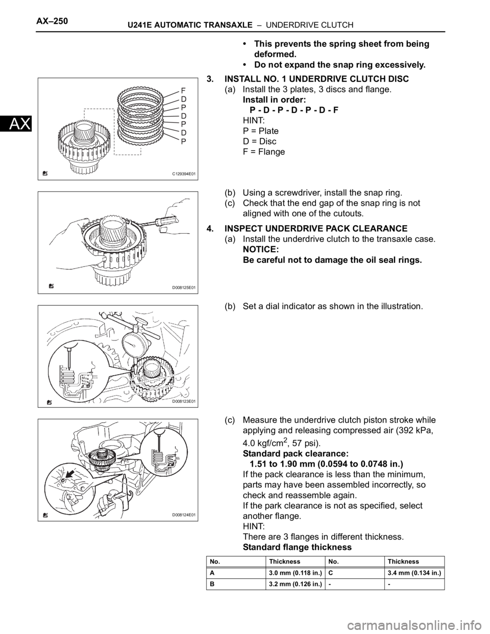
3. INSTALL NO. 1 UNDERDRIVE CLUTCH DISC
(a) Install the 3 plates, 3 discs and flange.
Install in order:
P - D - P - D - P - D - F
HINT:
P = Plate
D = Disc
F = Flange
(b) Using a screwdriver, install the snap ring.
(c) Check that the end gap of the snap ring is not
aligned with one of the cutouts.
4. INSPECT UNDERDRIVE PACK CLEARANCE
(a) Install the underdrive clutch to the transaxle case.
NOTICE:
Be careful not to damage the oil seal rings.
(b) Set a dial indicator as shown in the illustration.
(c) Measure the underdrive clutch piston stroke while
applying and releasing compressed air (392 kPa,
4.0 kgf/cm
2, 57 psi).
Standard pack clearance:
1.51 to 1.90 mm (0.0594 to 0.0748 in.)
If the pack clearance is less than the minimum,
parts may have been assembled incorrectly, so
check and reassemble again.
If the park clearance is not as specified, select
another flange.
HINT:
There are 3 flanges in different thickness.
Standard flange thickness
C129394E01
D008125E01
D008123E01
D008124E01
No. Thickness No. Thickness
A 3.0 mm (0.118 in.) C 3.4 mm (0.134 in.)
B 3.2 mm (0.126 in.) - -
Page 382 of 2000
GF1A TRANSFER – TRANSFER SYSTEMTF–3
TF
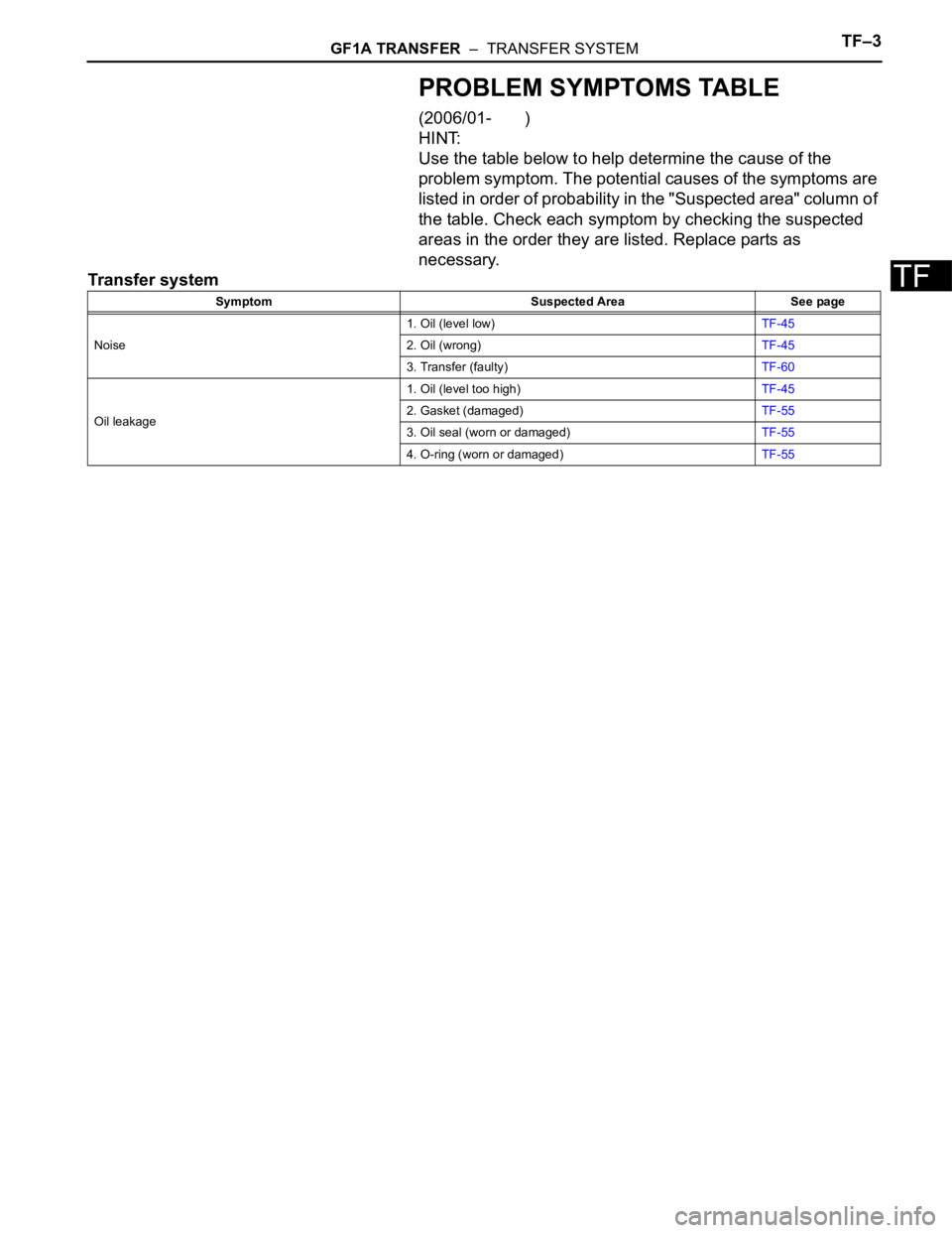
PROBLEM SYMPTOMS TABLE
(2006/01- )
HINT:
Use the table below to help determine the cause of the
problem symptom. The potential causes of the symptoms are
listed in order of probability in the "Suspected area" column of
the table. Check each symptom by checking the suspected
areas in the order they are listed. Replace parts as
necessary.
Transfer system
Symptom Suspected Area See page
Noise1. Oil (level low)TF-45
2. Oil (wrong)TF-45
3. Transfer (faulty)TF-60
Oil leakage1. Oil (level too high)TF-45
2. Gasket (damaged)TF-55
3. Oil seal (worn or damaged)TF-55
4. O-ring (worn or damaged)TF-55