2006 TOYOTA RAV4 mounting
[x] Cancel search: mountingPage 23 of 2000

ENGINE - 2AZ-FE ENGINE
01NEG45Y
RegulatorB
M
IG
RLO
L
Ignition Switch
To Discharge
Wa r n i n g L i g h t
Generator
ECM
281EG13
281EG12
Coil SpringPulley
Helical Coil Type One-way Clutch EG-26
Wiring Diagram
2. Generator Pulley
A helical coil type one-way clutch is used on the generator pulley in order to reduce the load that acts on
the auxiliary equipment belt.
The pulley mounting nut and the generator pulley have been integrated to achieve a compact construction.
Page 179 of 2000

SERVICE SPECIFICATIONS – U151E AUTOMATIC TRANSMISSIONSS–47
SS
TORQUE SPECIFICATIONS
Automatic Transaxle Assembly
Part Tightened N*m kgf*cm ft*lbf
Park/neutral position switch Nut 6.9 70 61 in.*lbf
Bolt 5.4 55 48 in.*lbf
Control shaft lever x Control shaft 13 133 10
Shift control cable x Control shaft lever 15 153 11
Transaxle housing x Engine block Upper side bolt 64 653 47
Lower side bolt
A37 377 27
Lower side bolt
B46 470 34
Torque converter clutch x Drive plate 41 418 30
Flywheel housing under cover x Automatic transaxle 7.8 80 69 in.*lbf
Front engine mounting bracket x Transaxle 64 653 47
Rear engine mounting bracket x Transaxle 45 459 33
Engine mounting bracket LH x Transaxle 64 653 47
Oil filler tube x Transaxle
Oil filler tube x Front engine mounting bracket5.5 56 49 in.*lbf
Control cable bracket No. 1 x Transaxle 12 122 9
Control cable bracket No. 2 x Transaxle 12 122 9
Oil cooler inlet elbow x Transaxle 27 276 20
Oil cooler outlet elbow x Transaxle 27 276 20
Starter x Transaxle37 377 27
Starter wire x Starter9.8 100 88 in.*lbf
Speed sensor (NC) x Transaxle 11 112 8
Speed sensor (NT) x Transaxle 11 112 8
Drain plug x Oil pan47 479 35
Transmission wire x Transaxle 5.4 55 48 in.*lbf
ATF temperature sensor x Valve body 6.6 67 58 in.*lbf
Oil pan x Transaxle7.8 80 69 in.*lbf
Solenoid valve x Valve body SL2, DSL, S4 11 110 8
SL1, SL3 6.6 67 58 in.*lbf
Valve body x Transaxle11 11 2 8
Oil strainer x Valve body11 11 2 8
Floor shift assembly x Body12 122 9
Control cable clamp x Engine mounting insulator 12 122 9
Differential gear lube apply tube x Transaxle housing 9.8 100 87 in.*lbf
Front planetary gear lock nut 280 3,355 207
Brake apply tube clamp x Transaxle case 5.4 55 48 in.*lbf
Transaxle case No. 1 plug x Transaxle rear cover 7.4 75 65 in.*lbf
Transaxle rear cover x Transaxle case Bolt A 19 194 14
Other bolt 25 255 18
Parking lock pawl shaft x Transaxle case 9.8 100 87 in.*lbf
Oil pump assembly x Transaxle case 22 226 16
Transaxle housing x Transaxle case Bolt A 22 254 16
Bolt B 29 295 21
Bolt C 29 295 21
Bolt D 22 254 16
Automatic transmission case plug x Transaxle housing 7.4 75 65 in.*lbf
Automatic transmission case plug x Transaxle case 7.4 75 65 in.*lbf
Page 200 of 2000

2GR-FE ENGINE MECHANICAL – ENGINE ASSEMBLYEM–25
EM
(b) Install an engine sling device to the engine and hold
the engine with a chain block.
CAUTION:
Do not raise the engine more than necessary. If
the engine is raised excessively, the vehicle may
also be lifted up.
(c) Set an engine lifter underneath the engine.
(d) Remove the column hole cover. Loosen the bolt
holding the intermediate shaft, and slide the
intermediate shaft.
(e) Put matchmarks on the intermediate shaft and
pinion.
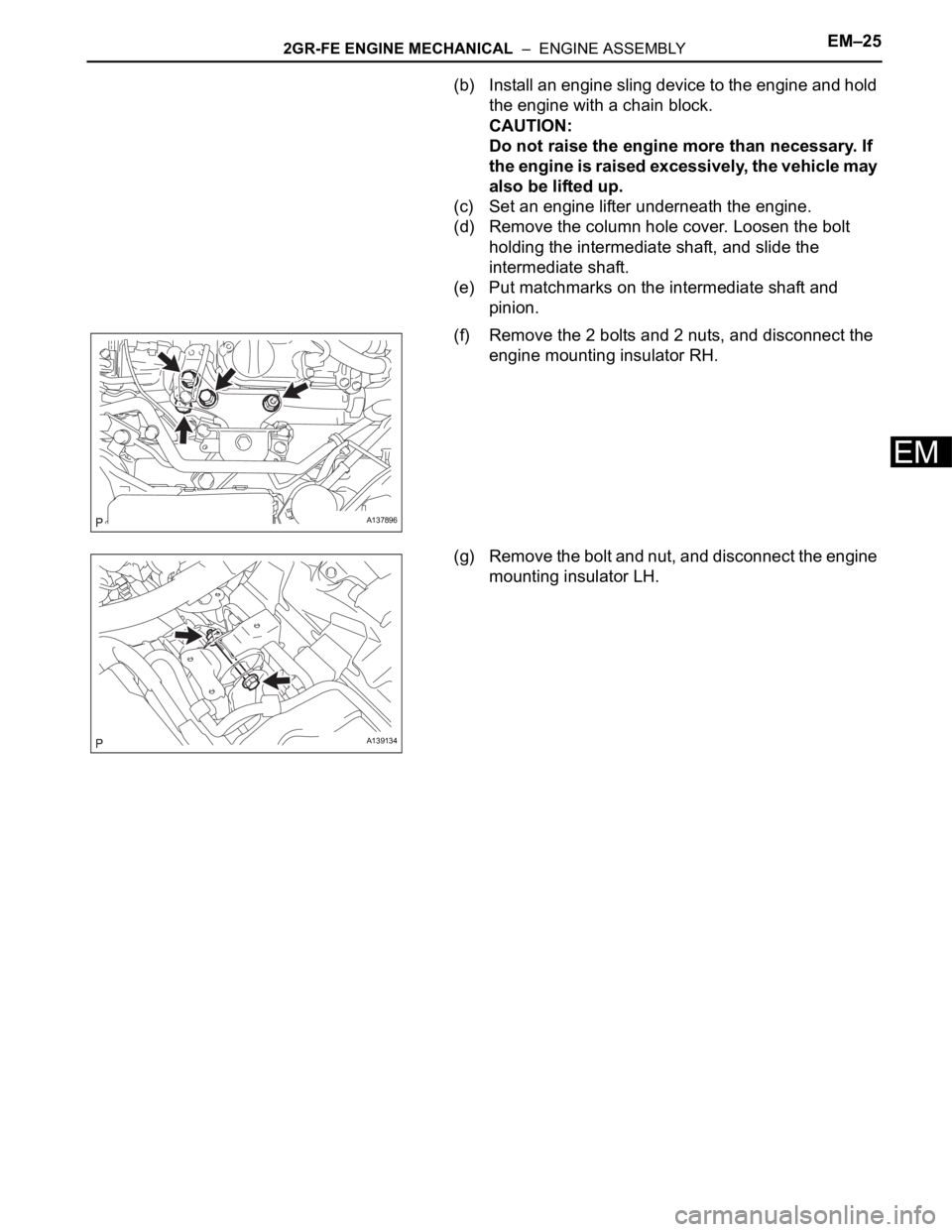
(f) Remove the 2 bolts and 2 nuts, and disconnect the
engine mounting insulator RH.
(g) Remove the bolt and nut, and disconnect the engine
mounting insulator LH.
A137896
A139134
Page 203 of 2000

EM–282GR-FE ENGINE MECHANICAL – ENGINE ASSEMBLY
EM
(g) Disconnect the connector.
(h) Using a 5 mm socket hexagon wrench, remove the
4 bolts.
(i) Remove the 2 nuts, 2 bolts and surge tank.
(j) Remove the gasket from the surge tank.
54. REMOVE IGNITION COIL ASSEMBLY
(a) Remove the 6 bolts and 6 coils from the cylinder
head.
55. REMOVE NO. 2 ENGINE MOUNTING STAY RH
(a) Remove the bolt and mounting stay.
56. REMOVE FUEL INJECTOR ASSEMBLY (See page
FU-14)
57. REMOVE INTAKE MANIFOLD
(a) Remove the 6 bolts, 4 nuts, intake manifold and 2
gaskets.
58. REMOVE EXHAUST MANIFOLD SUB-ASSEMBLY RH
(a) Disconnect the air fuel ratio sensor connector
clamp.
(b) Uniformly loosen and remove the 6 nuts.
(c) Remove the manifold and gasket.
59. REMOVE FAN AND GENERATOR V BELT (See page
EM-8)
60. REMOVE COMPRESSOR WITH PULLEY ASSEMBLY
(See page AC-220)
61. REMOVE GENERATOR ASSEMBLY (See page CH-12)
A129467
A129468
A076533E01
A139491
Page 204 of 2000

2GR-FE ENGINE MECHANICAL – ENGINE ASSEMBLYEM–29
EM
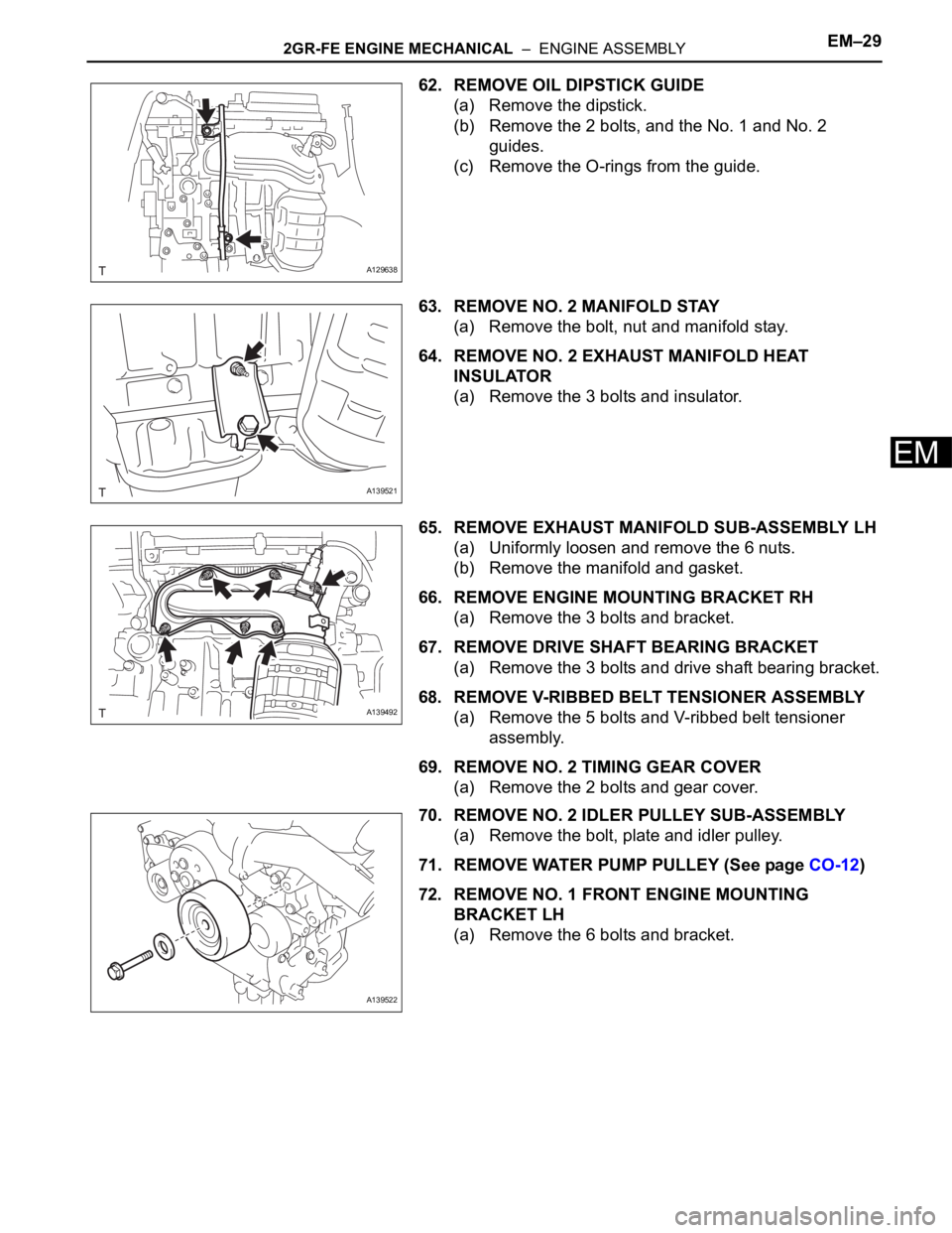
62. REMOVE OIL DIPSTICK GUIDE
(a) Remove the dipstick.
(b) Remove the 2 bolts, and the No. 1 and No. 2
guides.
(c) Remove the O-rings from the guide.
63. REMOVE NO. 2 MANIFOLD STAY
(a) Remove the bolt, nut and manifold stay.
64. REMOVE NO. 2 EXHAUST MANIFOLD HEAT
INSULATOR
(a) Remove the 3 bolts and insulator.
65. REMOVE EXHAUST MANIFOLD SUB-ASSEMBLY LH
(a) Uniformly loosen and remove the 6 nuts.
(b) Remove the manifold and gasket.
66. REMOVE ENGINE MOUNTING BRACKET RH
(a) Remove the 3 bolts and bracket.
67. REMOVE DRIVE SHAFT BEARING BRACKET
(a) Remove the 3 bolts and drive shaft bearing bracket.
68. REMOVE V-RIBBED BELT TENSIONER ASSEMBLY
(a) Remove the 5 bolts and V-ribbed belt tensioner
assembly.
69. REMOVE NO. 2 TIMING GEAR COVER
(a) Remove the 2 bolts and gear cover.
70. REMOVE NO. 2 IDLER PULLEY SUB-ASSEMBLY
(a) Remove the bolt, plate and idler pulley.
71. REMOVE WATER PUMP PULLEY (See page CO-12)
72. REMOVE NO. 1 FRONT ENGINE MOUNTING
BRACKET LH
(a) Remove the 6 bolts and bracket.
A129638
A139521
A139492
A139522
Page 379 of 2000

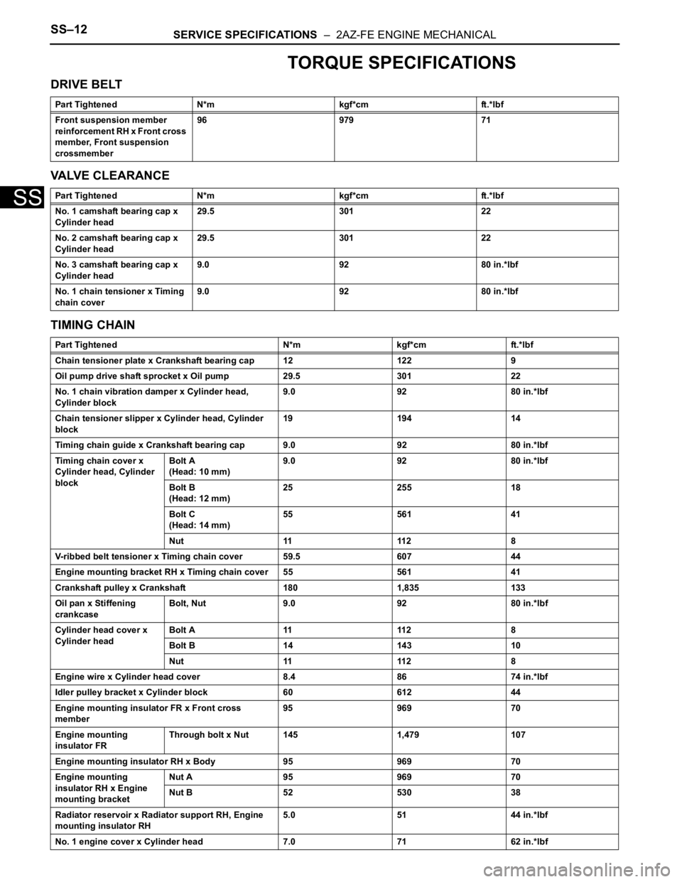
SS–12SERVICE SPECIFICATIONS – 2AZ-FE ENGINE MECHANICAL
SS
TORQUE SPECIFICATIONS
DRIVE BELT
VALVE CLEARANCE
TIMING CHAIN
Part Tightened N*m kgf*cm ft.*lbf
Front suspension member
reinforcement RH x Front cross
member, Front suspension
crossmember96 979 71
Part Tightened N*m kgf*cm ft.*lbf
No. 1 camshaft bearing cap x
Cylinder head29.5 301 22
No. 2 camshaft bearing cap x
Cylinder head29.5 301 22
No. 3 camshaft bearing cap x
Cylinder head9.0 92 80 in.*lbf
No. 1 chain tensioner x Timing
chain cover9.0 92 80 in.*lbf
Part Tightened N*m kgf*cm ft.*lbf
Chain tensioner plate x Crankshaft bearing cap 12 122 9
Oil pump drive shaft sprocket x Oil pump 29.5 301 22
No. 1 chain vibration damper x Cylinder head,
Cylinder block9.0 92 80 in.*lbf
Chain tensioner slipper x Cylinder head, Cylinder
block19 194 14
Timing chain guide x Crankshaft bearing cap 9.0 92 80 in.*lbf
Timing chain cover x
Cylinder head, Cylinder
blockBolt A
(Head: 10 mm)9.0 92 80 in.*lbf
Bolt B
(Head: 12 mm)25 255 18
Bolt C
(Head: 14 mm)55 561 41
Nut 11 112 8
V-ribbed belt tensioner x Timing chain cover 59.5 607 44
Engine mounting bracket RH x Timing chain cover 55 561 41
Crankshaft pulley x Crankshaft 180 1,835 133
Oil pan x Stiffening
crankcaseBolt, Nut 9.0 92 80 in.*lbf
Cylinder head cover x
Cylinder headBolt A 11 112 8
Bolt B 14 143 10
Nut 11 112 8
Engine wire x Cylinder head cover 8.4 86 74 in.*lbf
Idler pulley bracket x Cylinder block 60 612 44
Engine mounting insulator FR x Front cross
member95 969 70
Engine mounting
insulator FRThrough bolt x Nut 145 1,479 107
Engine mounting insulator RH x Body 95 969 70
Engine mounting
insulator RH x Engine
mounting bracketNut A 95 969 70
Nut B 52 530 38
Radiator reservoir x Radiator support RH, Engine
mounting insulator RH5.0 51 44 in.*lbf
No. 1 engine cover x Cylinder head 7.0 71 62 in.*lbf
Page 380 of 2000

SERVICE SPECIFICATIONS – 2AZ-FE ENGINE MECHANICALSS–13
SS
CYLINDER HEAD
ENGINE ASSEMBLY
Part Tightened N*m kgf*cm ft.*lbf
Camshaft position sensor x Cylinder head 9.0 92 80 in.*lbf
Oil pressure switch x Cylinder head 13 133 10
Radio setting condenser x Cylinder head 10 102 7
Cylinder head set bolt
Cylinder head x Cylinder
block1 st 70 714 52
2 nd Turn 90
Tu r n 9 0Tu r n 9 0
Camshaft timing gear x Camshaft 54 551 40
No. 2 camshaft timing sprocket x No. 2 camshaft 54 551 40
No. 1 and No. 2 camshaft bearing cap x Cylinder
head29.5 301 22
No. 3 camshaft bearing cap x Cylinder head 9.0 92 80 in.*lbf
Exhaust manifold x Cylinder head 37 377 27
No. 1 exhaust manifold heat insulator x Exhaust
manifold12 122 9
No. 1 and No. 2 manifold stay x Cylinder block,
Exhaust manifold44 449 32
Oil dipstick guide x Cylinder block 9.0 92 80 in.*lbf
Part Tightened N*m kgf*cm ft.*lbf
Drive plate x Crankshaft 98 1,000 72
Drive shaft bearing bracket x Cylinder block 64 653 47
No. 1 and No. 2 engine hanger x Cylinder head 38 387 28
Engine mounting insulator LH x Body 95 969 70
Engine mounting
insulator LHThrough bolt 56 571 41
Engine mounting insulator RH x Body 95 969 70
Engine mounting
insulator RH x Engine
mounting bracketNut A 95 969 70
Nut B 52 530 38
Engine mounting
insulator RR x Front
suspension
crossmemberBolt and Nut 95 969 70
Engine mounting
insulator RR x Engine
mounting bracketThough bolt 95 969 70
Engine mounting insulator FR x Front cross
member95 969 70
Engine mounting
insulator FRThough bolt 145 1,479 107
Battery carrier bracket x Body 20 204 15
Battery bracket reinforcement x Battery carrier 20 204 15
Front battery carrier x Battery bracket
reinforcement20 204 15
Air cleaner filter element x Body 5.0 51 44 in.*lbf
Radiator reservoir x Radiator support RH, Engine
mounting insulator RH5.0 51 44 in.*lbf
Battery clamp x Upper
Radiator supportFor bolt 8.5 87 75 in.*lbf
Battery clamp x Battery
clamp boltFor nut 5.0 51 44 in.*lbf
Page 383 of 2000

SERVICE SPECIFICATIONS – 2GR-FE ENGINE MECHANICALSS–21
SS
TORQUE SPECIFICATIONS
Part Tightened N*m kgf*cm ft.*lbf
Front suspension member reinforcement RH x Front
crossmember95 969 70
Front suspension member reinforcement RH x Front
suspension crossmember95 969 70
Radiator reservoir tank x Bract 5.0 51 44 in.*lbf
Engine coolant temperature sensor x Water outlet 20 204 14
Engine oil pressure sensor x Oil pan 21 214 15
No. 1 front engine mounting bracket LH x Timing chain
cover54 551 40
No. 2 idler pulley x Timing chain cover 43 438 32
No. 2 timing gear cover x Timing chain cover 6.0 61 53 in.*lbf
V-ribbed belt tensioner x Timing chain cover 43 438 32
V-ribbed belt tensioner x Cylinder block 43 438 32
Drive shaft bearing bracket x Cylinder block 64 653 47
Exhaust manifold LH x Cylinder head 21 214 15
No. 2 exhaust heat insulator x Exhaust manifold 8.5 87 75 in.*lbf
No. 2 manifold stay x Exhaust manifold 34 347 25
No. 2 manifold stay x Cylinder block 34 347 25
No. 1 oil dipstick guide x Cylinder block 21 214 15
No. 2 oil dipstick guide x Cylinder head 21 214 15
Exhaust manifold RH x Cylinder head 21 214 15
Intake manifold x Cylinder head 21 214 15
No. 2 engine mounting stay RH x Intake manifold 21 214 15
No. 2 engine mounting stay RH x Timing chain cover 21 214 15
Ignition coil x Cylinder head cover 10 102 7
Intake air surge tank x
Intake manifold5 mm hexagon wrench 18 184 13
for Bolt 21 214 15
for Nut 16 163 12
Vacuum hose clamp x Intake air surge tank 5.4 55 48 in.*lbf
Drive plate and ring gear x Crankshaft 178 1,815 132
Engine mounting bracket RR x Engine mounting
insulator RR95 969 70
Engine mounting bracket FR x Engine mounting
insulator FR145 1,479 107
Engine mounting bracket LH x Engine mounting
insulator LH56 571 41
Engine mounting insulator
RH x Front No. 1 engine
mounting bracketfor Bolt and nut A 95 969 70
for Nut B 52 530 38
Front crossmember x
Bodyfor Bolt A 96 979 71
Front suspension member
x Bodyfor Bolt B 145 1,478 107
Front suspension member
brace rear x Bodyfor Bolt C 145 1,478 107
for Bolt D 93 948 69
Air cleaner case x Engine mounting insulator LH 5.0 51 44 in.*lbf
Battery bracket reinforcement x Body 19 194 14
Front battery bracket x Body 19 194 14
Front battery bracket x Battery bracket reinforcement 19 194 14
Battery clamp x Body 5.0 51 44 in.*lbf