Page 1378 of 2000

DS–22DRIVE SHAFT – FRONT DRIVE SHAFT ASSEMBLY (for 2WD)
DS
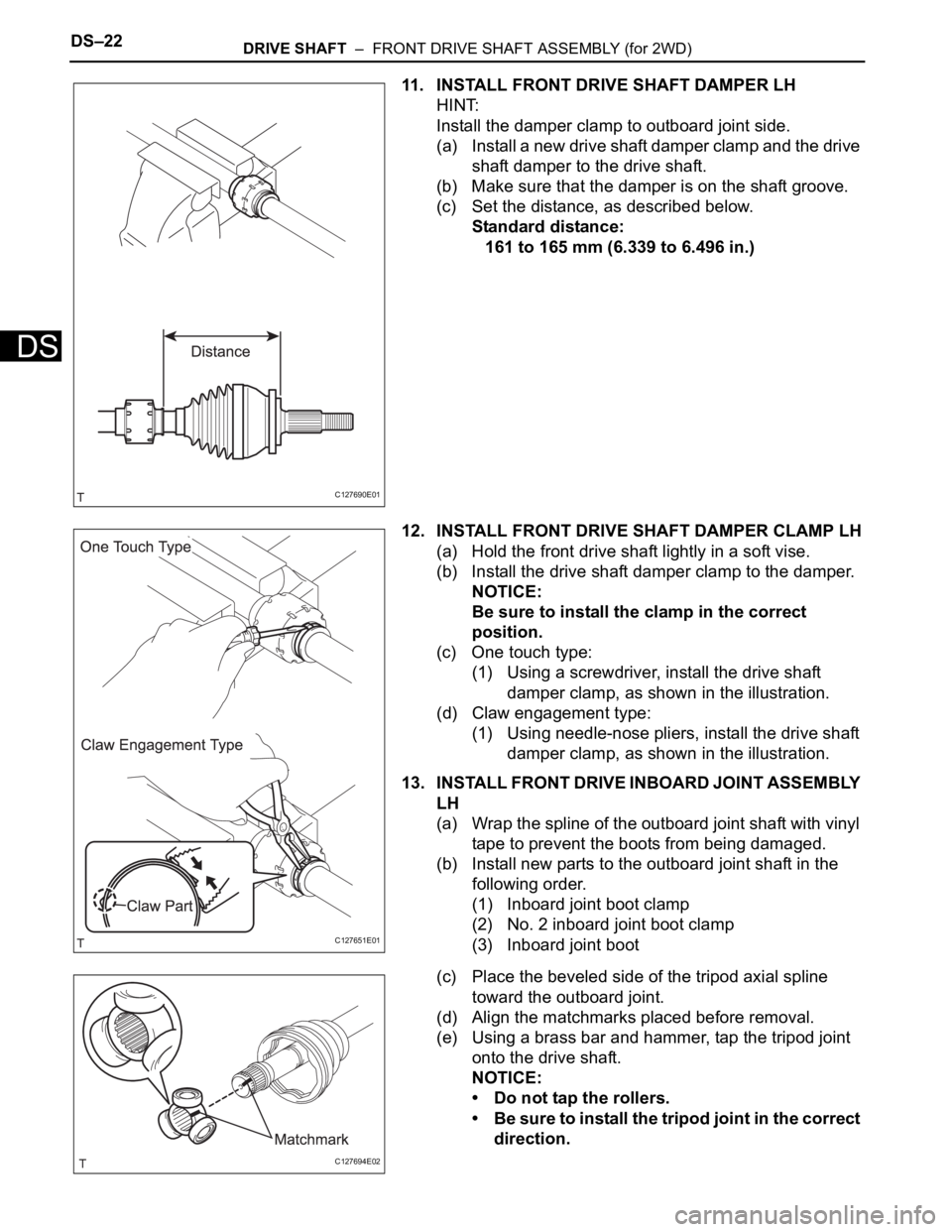
11. INSTALL FRONT DRIVE SHAFT DAMPER LH
HINT:
Install the damper clamp to outboard joint side.
(a) Install a new drive shaft damper clamp and the drive
shaft damper to the drive shaft.
(b) Make sure that the damper is on the shaft groove.
(c) Set the distance, as described below.
Standard distance:
161 to 165 mm (6.339 to 6.496 in.)
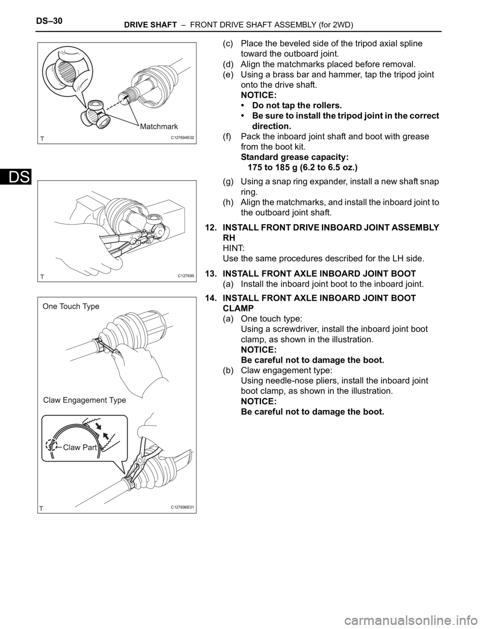
12. INSTALL FRONT DRIVE SHAFT DAMPER CLAMP LH
(a) Hold the front drive shaft lightly in a soft vise.
(b) Install the drive shaft damper clamp to the damper.
NOTICE:
Be sure to install the clamp in the correct
position.
(c) One touch type:
(1) Using a screwdriver, install the drive shaft
damper clamp, as shown in the illustration.
(d) Claw engagement type:
(1) Using needle-nose pliers, install the drive shaft
damper clamp, as shown in the illustration.
13. INSTALL FRONT DRIVE INBOARD JOINT ASSEMBLY
LH
(a) Wrap the spline of the outboard joint shaft with vinyl
tape to prevent the boots from being damaged.
(b) Install new parts to the outboard joint shaft in the
following order.
(1) Inboard joint boot clamp
(2) No. 2 inboard joint boot clamp
(3) Inboard joint boot
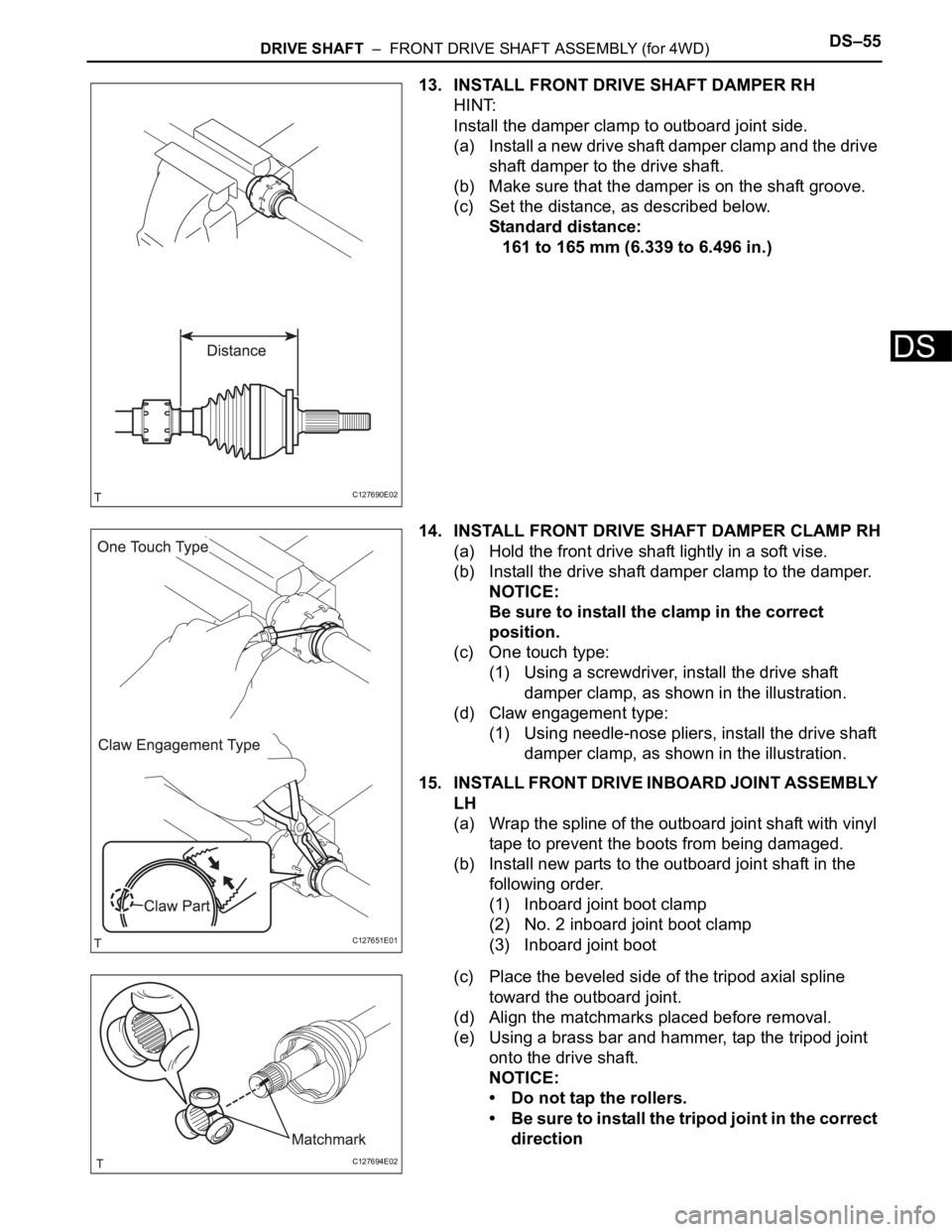
(c) Place the beveled side of the tripod axial spline
toward the outboard joint.
(d) Align the matchmarks placed before removal.
(e) Using a brass bar and hammer, tap the tripod joint
onto the drive shaft.
NOTICE:
• Do not tap the rollers.
• Be sure to install the tripod joint in the correct
direction.
C127690E01
C127651E01
C127694E02
Page 1386 of 2000

DS–30DRIVE SHAFT – FRONT DRIVE SHAFT ASSEMBLY (for 2WD)
DS
(c) Place the beveled side of the tripod axial spline
toward the outboard joint.
(d) Align the matchmarks placed before removal.
(e) Using a brass bar and hammer, tap the tripod joint
onto the drive shaft.
NOTICE:
• Do not tap the rollers.
• Be sure to install the tripod joint in the correct
direction.
(f) Pack the inboard joint shaft and boot with grease
from the boot kit.
Standard grease capacity:
175 to 185 g (6.2 to 6.5 oz.)
(g) Using a snap ring expander, install a new shaft snap
ring.
(h) Align the matchmarks, and install the inboard joint to
the outboard joint shaft.
12. INSTALL FRONT DRIVE INBOARD JOINT ASSEMBLY
RH
HINT:
Use the same procedures described for the LH side.
13. INSTALL FRONT AXLE INBOARD JOINT BOOT
(a) Install the inboard joint boot to the inboard joint.
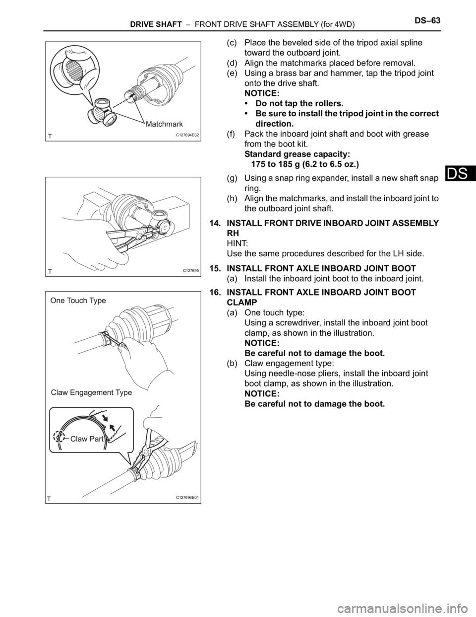
14. INSTALL FRONT AXLE INBOARD JOINT BOOT
CLAMP
(a) One touch type:
Using a screwdriver, install the inboard joint boot
clamp, as shown in the illustration.
NOTICE:
Be careful not to damage the boot.
(b) Claw engagement type:
Using needle-nose pliers, install the inboard joint
boot clamp, as shown in the illustration.
NOTICE:
Be careful not to damage the boot.
C127694E02
C127695
C127696E01
Page 1409 of 2000

DRIVE SHAFT – FRONT DRIVE SHAFT ASSEMBLY (for 4WD)DS–55
DS
13. INSTALL FRONT DRIVE SHAFT DAMPER RH
HINT:
Install the damper clamp to outboard joint side.
(a) Install a new drive shaft damper clamp and the drive
shaft damper to the drive shaft.
(b) Make sure that the damper is on the shaft groove.
(c) Set the distance, as described below.
Standard distance:
161 to 165 mm (6.339 to 6.496 in.)
14. INSTALL FRONT DRIVE SHAFT DAMPER CLAMP RH
(a) Hold the front drive shaft lightly in a soft vise.
(b) Install the drive shaft damper clamp to the damper.
NOTICE:
Be sure to install the clamp in the correct
position.
(c) One touch type:
(1) Using a screwdriver, install the drive shaft
damper clamp, as shown in the illustration.
(d) Claw engagement type:
(1) Using needle-nose pliers, install the drive shaft
damper clamp, as shown in the illustration.
15. INSTALL FRONT DRIVE INBOARD JOINT ASSEMBLY
LH
(a) Wrap the spline of the outboard joint shaft with vinyl
tape to prevent the boots from being damaged.
(b) Install new parts to the outboard joint shaft in the
following order.
(1) Inboard joint boot clamp
(2) No. 2 inboard joint boot clamp
(3) Inboard joint boot
(c) Place the beveled side of the tripod axial spline
toward the outboard joint.
(d) Align the matchmarks placed before removal.
(e) Using a brass bar and hammer, tap the tripod joint
onto the drive shaft.
NOTICE:
• Do not tap the rollers.
• Be sure to install the tripod joint in the correct
direction
C127690E02
C127651E01
C127694E02
Page 1417 of 2000

DRIVE SHAFT – FRONT DRIVE SHAFT ASSEMBLY (for 4WD)DS–63
DS
(c) Place the beveled side of the tripod axial spline
toward the outboard joint.
(d) Align the matchmarks placed before removal.
(e) Using a brass bar and hammer, tap the tripod joint
onto the drive shaft.
NOTICE:
• Do not tap the rollers.
• Be sure to install the tripod joint in the correct
direction.
(f) Pack the inboard joint shaft and boot with grease
from the boot kit.
Standard grease capacity:
175 to 185 g (6.2 to 6.5 oz.)
(g) Using a snap ring expander, install a new shaft snap
ring.
(h) Align the matchmarks, and install the inboard joint to
the outboard joint shaft.
14. INSTALL FRONT DRIVE INBOARD JOINT ASSEMBLY
RH
HINT:
Use the same procedures described for the LH side.
15. INSTALL FRONT AXLE INBOARD JOINT BOOT
(a) Install the inboard joint boot to the inboard joint.
16. INSTALL FRONT AXLE INBOARD JOINT BOOT
CLAMP
(a) One touch type:
Using a screwdriver, install the inboard joint boot
clamp, as shown in the illustration.
NOTICE:
Be careful not to damage the boot.
(b) Claw engagement type:
Using needle-nose pliers, install the inboard joint
boot clamp, as shown in the illustration.
NOTICE:
Be careful not to damage the boot.
C127694E02
C127695
C127696E01