Page 179 of 2000

SERVICE SPECIFICATIONS – U151E AUTOMATIC TRANSMISSIONSS–47
SS
TORQUE SPECIFICATIONS
Automatic Transaxle Assembly
Part Tightened N*m kgf*cm ft*lbf
Park/neutral position switch Nut 6.9 70 61 in.*lbf
Bolt 5.4 55 48 in.*lbf
Control shaft lever x Control shaft 13 133 10
Shift control cable x Control shaft lever 15 153 11
Transaxle housing x Engine block Upper side bolt 64 653 47
Lower side bolt
A37 377 27
Lower side bolt
B46 470 34
Torque converter clutch x Drive plate 41 418 30
Flywheel housing under cover x Automatic transaxle 7.8 80 69 in.*lbf
Front engine mounting bracket x Transaxle 64 653 47
Rear engine mounting bracket x Transaxle 45 459 33
Engine mounting bracket LH x Transaxle 64 653 47
Oil filler tube x Transaxle
Oil filler tube x Front engine mounting bracket5.5 56 49 in.*lbf
Control cable bracket No. 1 x Transaxle 12 122 9
Control cable bracket No. 2 x Transaxle 12 122 9
Oil cooler inlet elbow x Transaxle 27 276 20
Oil cooler outlet elbow x Transaxle 27 276 20
Starter x Transaxle37 377 27
Starter wire x Starter9.8 100 88 in.*lbf
Speed sensor (NC) x Transaxle 11 112 8
Speed sensor (NT) x Transaxle 11 112 8
Drain plug x Oil pan47 479 35
Transmission wire x Transaxle 5.4 55 48 in.*lbf
ATF temperature sensor x Valve body 6.6 67 58 in.*lbf
Oil pan x Transaxle7.8 80 69 in.*lbf
Solenoid valve x Valve body SL2, DSL, S4 11 110 8
SL1, SL3 6.6 67 58 in.*lbf
Valve body x Transaxle11 11 2 8
Oil strainer x Valve body11 11 2 8
Floor shift assembly x Body12 122 9
Control cable clamp x Engine mounting insulator 12 122 9
Differential gear lube apply tube x Transaxle housing 9.8 100 87 in.*lbf
Front planetary gear lock nut 280 3,355 207
Brake apply tube clamp x Transaxle case 5.4 55 48 in.*lbf
Transaxle case No. 1 plug x Transaxle rear cover 7.4 75 65 in.*lbf
Transaxle rear cover x Transaxle case Bolt A 19 194 14
Other bolt 25 255 18
Parking lock pawl shaft x Transaxle case 9.8 100 87 in.*lbf
Oil pump assembly x Transaxle case 22 226 16
Transaxle housing x Transaxle case Bolt A 22 254 16
Bolt B 29 295 21
Bolt C 29 295 21
Bolt D 22 254 16
Automatic transmission case plug x Transaxle housing 7.4 75 65 in.*lbf
Automatic transmission case plug x Transaxle case 7.4 75 65 in.*lbf
Page 312 of 2000
PREPARATION – U151E AUTOMATIC TRANSMISSIONPP–41
PP
LUBRICANT
Automatic transaxle fluid
Dry fill
Drain and refill8.1 liter (8.6 US qts, 7.1 Imp.qts)
3.6 liter (3.8 US qts, 3.2 Imp.qts)Toyota Genuine ATF WS
Page 316 of 2000
PREPARATION – U151F AUTOMATIC TRANSMISSIONPP–47
PP
LUBRICANT
Automatic transaxle fluid
Dry fill
Drain and refill8.1 liter (8.6 US qts, 7.1 Imp.qts)
3.6 liter (3.8 US qts, 3.2 Imp.qts)Toyota Genuine ATF WS
Page 320 of 2000
PP–54PREPARATION – U140F AUTOMATIC TRANSAXLE
PP
LUBRICANT
Automatic transaxle fluid
Dry fill (w/ Warmer)8.1 liters (8.6 US qts, 7.2 Imp. qts) Toyota Genuine ATF WS
Automatic transaxle fluid
Drain and refill (w/ Warmer)3.5 liters (3.7 US qts, 3.1 Imp. qts)
Page 324 of 2000
PREPARATION – U241E AUTOMATIC TRANSAXLEPP–61
PP
LUBRICANT
Automatic transaxle fluid
Dry fill8.1 liters (8.6 US qts, 7.2 Imp. qts) Toyota Genuine ATF WS
Automatic transaxle fluid
Drain and refill3.5 liters (3.7 US qts, 3.1 Imp. qts)
Page 364 of 2000

AX–288U151F AUTOMATIC TRANSAXLE – DIFFERENTIAL CASE
AX
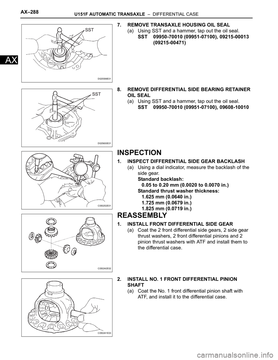
7. REMOVE TRANSAXLE HOUSING OIL SEAL
(a) Using SST and a hammer, tap out the oil seal.
SST 09950-70010 (09951-07100), 09215-00013
(09215-00471)
8. REMOVE DIFFERENTIAL SIDE BEARING RETAINER
OIL SEAL
(a) Using SST and a hammer, tap out the oil seal.
SST 09950-70010 (09951-07100), 09608-10010
INSPECTION
1. INSPECT DIFFERENTIAL SIDE GEAR BACKLASH
(a) Using a dial indicator, measure the backlash of the
side gear.
Standard backlash:
0.05 to 0.20 mm (0.0020 to 0.0070 in.)
Standard thrust washer thickness:
1.625 mm (0.0640 in.)
1.725 mm (0.0679 in.)
1.825 mm (0.0719 in.)
REASSEMBLY
1. INSTALL FRONT DIFFERENTIAL SIDE GEAR
(a) Coat the 2 front differential side gears, 2 side gear
thrust washers, 2 front differential pinions and 2
pinion thrust washers with ATF and install them to
the differential case.
2. INSTALL NO. 1 FRONT DIFFERENTIAL PINION
SHAFT
(a) Coat the No. 1 front differential pinion shaft with
ATF, and install it to the differential case.
D025599E01
D025600E01
C050252E01
C050242E02
C050241E03
Page 368 of 2000
AX–292U151F AUTOMATIC TRANSAXLE – DIFFERENTIAL CASE
AX
(f) Remove the 16 bolts and the transaxle housing.
(g) Remove the differential assembly.
7. INSTALL FRONT DIFFERENTIAL RING GEAR
(a) Using ATF and a heater, heat the front differential
ring gear to 90 to 110
C (194.0 to 230.0F).
NOTICE:
Do not overheat the ring gear to 110
C (230.0F)
or more.
(b) Clean the contract surface of the front differential
case.
(c) Align the matchmarks, and install the front
differential ring gear case quickly.
NOTICE:
• Check the position and number of the
grooves on each end face of the differential
ring gear.
• Do not install the bolts while the ring gear is
hot.
(d) Tighten the 14 bolts.
Torque: 95 N*m (969 kgf*cm, 70 ft.*lbf)
NOTICE:
Tighten the bolts a little at a time in diagonal
order.
C050259E02
C127429
D025215E03
C140285E01
C127422
Page 376 of 2000

AX–248U241E AUTOMATIC TRANSAXLE – UNDERDRIVE CLUTCH
AX
INSPECTION
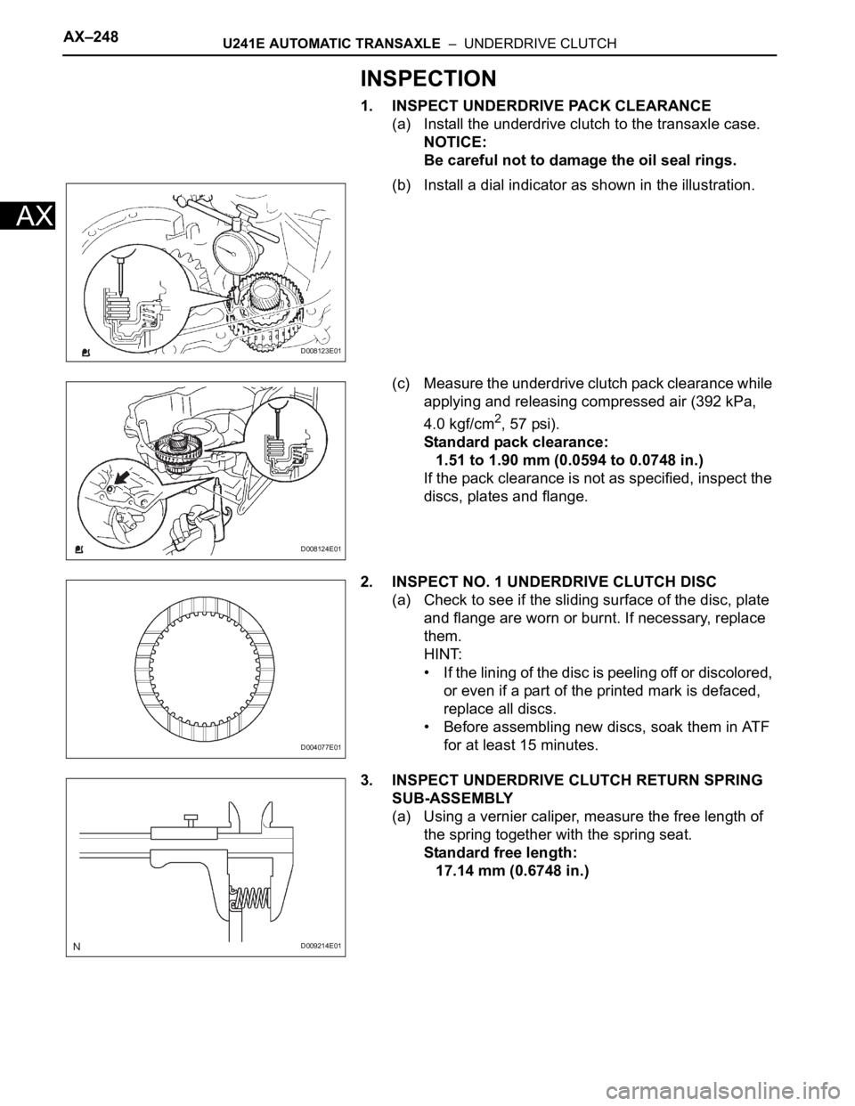
1. INSPECT UNDERDRIVE PACK CLEARANCE
(a) Install the underdrive clutch to the transaxle case.
NOTICE:
Be careful not to damage the oil seal rings.
(b) Install a dial indicator as shown in the illustration.
(c) Measure the underdrive clutch pack clearance while
applying and releasing compressed air (392 kPa,
4.0 kgf/cm
2, 57 psi).
Standard pack clearance:
1.51 to 1.90 mm (0.0594 to 0.0748 in.)
If the pack clearance is not as specified, inspect the
discs, plates and flange.
2. INSPECT NO. 1 UNDERDRIVE CLUTCH DISC
(a) Check to see if the sliding surface of the disc, plate
and flange are worn or burnt. If necessary, replace
them.
HINT:
• If the lining of the disc is peeling off or discolored,
or even if a part of the printed mark is defaced,
replace all discs.
• Before assembling new discs, soak them in ATF
for at least 15 minutes.
3. INSPECT UNDERDRIVE CLUTCH RETURN SPRING
SUB-ASSEMBLY
(a) Using a vernier caliper, measure the free length of
the spring together with the spring seat.
Standard free length:
17.14 mm (0.6748 in.)
D008123E01
D008124E01
D004077E01
D009214E01