Page 1007 of 2000
U140F AUTOMATIC TRANSAXLE – AUTOMATIC TRANSAXLE UNITAX–213
AX
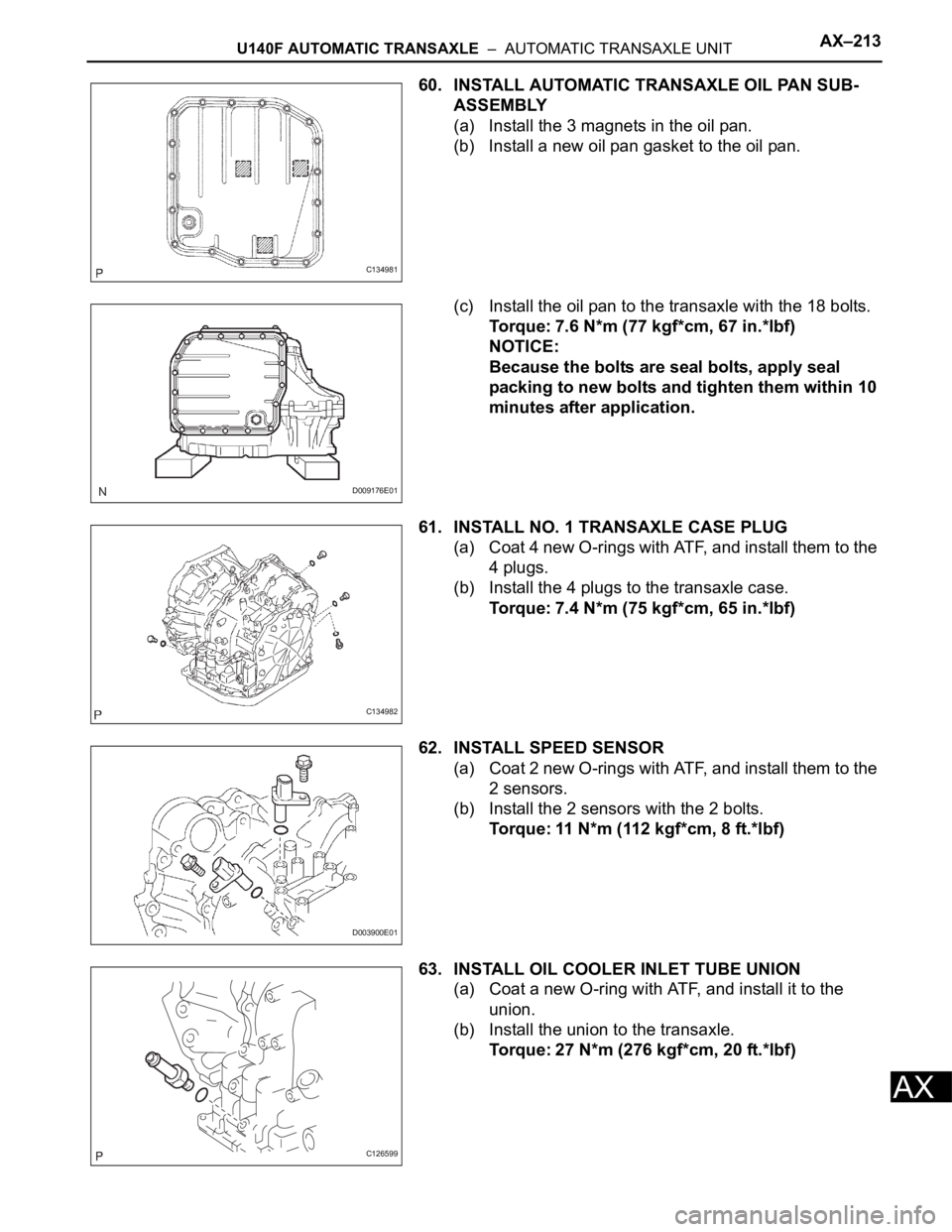
60. INSTALL AUTOMATIC TRANSAXLE OIL PAN SUB-
ASSEMBLY
(a) Install the 3 magnets in the oil pan.
(b) Install a new oil pan gasket to the oil pan.
(c) Install the oil pan to the transaxle with the 18 bolts.
Torque: 7.6 N*m (77 kgf*cm, 67 in.*lbf)
NOTICE:
Because the bolts are seal bolts, apply seal
packing to new bolts and tighten them within 10
minutes after application.
61. INSTALL NO. 1 TRANSAXLE CASE PLUG
(a) Coat 4 new O-rings with ATF, and install them to the
4 plugs.
(b) Install the 4 plugs to the transaxle case.
Torque: 7.4 N*m (75 kgf*cm, 65 in.*lbf)
62. INSTALL SPEED SENSOR
(a) Coat 2 new O-rings with ATF, and install them to the
2 sensors.
(b) Install the 2 sensors with the 2 bolts.
Torque: 11 N*m (112 kgf*cm, 8 ft.*lbf)
63. INSTALL OIL COOLER INLET TUBE UNION
(a) Coat a new O-ring with ATF, and install it to the
union.
(b) Install the union to the transaxle.
Torque: 27 N*m (276 kgf*cm, 20 ft.*lbf)
C134981
D009176E01
C134982
D003900E01
C126599
Page 1008 of 2000
AX–214U140F AUTOMATIC TRANSAXLE – AUTOMATIC TRANSAXLE UNIT
AX
64. INSTALL OIL COOLER OUTLET TUBE UNION
(a) Coat a new O-ring with ATF, and install it to the
union.
(b) Install the union to the transaxle.
Torque: 25 N*m (255 kgf*cm, 18 ft.*lbf)
65. INSTALL BREATHER PLUG HOSE
66. INSTALL PARK/NEUTRAL POSITION SWITCH
ASSEMBLY
(a) Install the park/neutral position switch to the manual
valve shaft.
(b) Temporarily install the 2 bolts.
(c) Install a new lock plate and tighten the manual valve
shaft nut.
Torque: 5.4 N*m (55 kgf*cm, 48 in.*lbf)
(d) Temporarily install the control shaft lever.
(e) Turn the lever counterclockwise until it stops, and
then turn it clockwise 2 notches.
(f) Remove the control shaft lever.
(g) Align the groove with neutral basic line.
(h) Hold the switch in this position and tighten the 2
bolts.
Torque: 6.9 N*m (70 kgf*cm, 61 in.*lbf)
C127809
D009639E02
D009640E02
D009641E01
D009642E01
Page 1010 of 2000
AX–220U140F AUTOMATIC TRANSAXLE – OIL PUMP
AX
REASSEMBLY
1. INSTALL FRONT OIL PUMP OIL SEAL
(a) Using SST and a hammer, install a new oil seal to
the pump.
SST 09350-32014 (09351-32140)
HINT:
The seal end should be flat with the outer edge of
the oil pump.
(b) Coat the lip of the oil seal with petroleum jelly.
2. INSTALL FRONT OIL PUMP BODY O-RING
(a) Coat the new O-ring with ATF, and install it to the oil
pump body.
3. INSTALL FRONT OIL PUMP DRIVEN GEAR
(a) Coat the front oil pump driven gear with ATF, and
install it to the oil pump body with the marked side
facing up.
4. INSTALL FRONT OIL PUMP DRIVE GEAR
(a) Coat the front oil pump drive gear with ATF, and
install it to the oil pump body with the marked side
facing up.
5. INSTALL STATOR SHAFT ASSEMBLY
(a) Set the stator shaft by aligning each bolt hole.
(b) Using a T30 ''trox'' socket, install the 11 bolts.
Torque: 9.8 N*m (100 kgf*cm, 87 in.*lbf)
D003654E01
C055817E03
D009206E08
D009206E09
D003651E02
Page 1012 of 2000
AX–224U140F AUTOMATIC TRANSAXLE – SECOND BRAKE PISTON
AX
REASSEMBLY
1. INSTALL 2ND BRAKE PISTON O-RING
(a) Coat the 2 new O-rings with ATF, and install them
into the 2nd brake piston.
2. INSTALL 2ND BRAKE PISTON
(a) Press in the 2nd brake piston into the 2nd brake
cylinder with your hands.
3. INSTALL 2ND BRAKE PISTON RETURN SPRING
SUB-ASSEMBLY
(a) Install the piston return spring.
(b) Place SST on the piston return spring, and
compress the piston return spring with a press.
SST 09387-00060
(c) Using a screwdriver, install the snap ring.
NOTICE:
Be sure the end gap of the snap ring is not
aligned with the piston return spring claw.
D003846E02
D003845E01
D003843E02
D003796E04
Page 1013 of 2000
AX–234U140F AUTOMATIC TRANSAXLE – DIRECT CLUTCH
AX
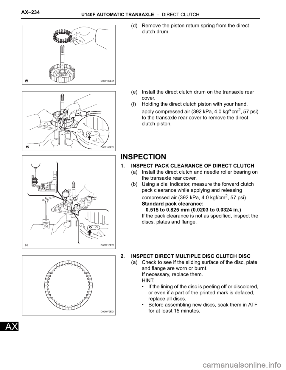
(d) Remove the piston return spring from the direct
clutch drum.
(e) Install the direct clutch drum on the transaxle rear
cover.
(f) Holding the direct clutch piston with your hand,
apply compressed air (392 kPa, 4.0 kgf*cm
2, 57 psi)
to the transaxle rear cover to remove the direct
clutch piston.
INSPECTION
1. INSPECT PACK CLEARANCE OF DIRECT CLUTCH
(a) Install the direct clutch and needle roller bearing on
the transaxle rear cover.
(b) Using a dial indicator, measure the forward clutch
pack clearance while applying and releasing
compressed air (392 kPa, 4.0 kgf/cm
2, 57 psi)
Standard pack clearance:
0.515 to 0.825 mm (0.0203 to 0.0324 in.)
If the pack clearance is not as specified, inspect the
discs, plates and flange.
2. INSPECT DIRECT MULTIPLE DISC CLUTCH DISC
(a) Check to see if the sliding surface of the disc, plate
and flange are worn or burnt.
If necessary, replace them.
HINT:
• If the lining of the disc is peeling off or discolored,
or even if a part of the printed mark is defaced,
replace all discs.
• Before assembling new discs, soak them in ATF
for at least 15 minutes.
D008102E01
D008103E01
D009210E01
D004079E01
Page 1014 of 2000
U140F AUTOMATIC TRANSAXLE – DIRECT CLUTCHAX–235
AX
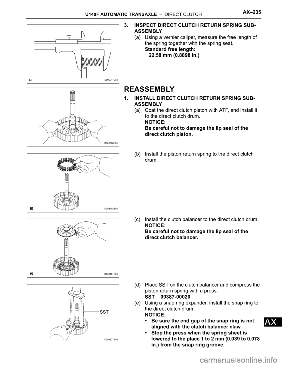
3. INSPECT DIRECT CLUTCH RETURN SPRING SUB-
ASSEMBLY
(a) Using a vernier caliper, measure the free length of
the spring together with the spring seat.
Standard free length:
22.58 mm (0.8898 in.)
REASSEMBLY
1. INSTALL DIRECT CLUTCH RETURN SPRING SUB-
ASSEMBLY
(a) Coat the direct clutch piston with ATF, and install it
to the direct clutch drum.
NOTICE:
Be careful not to damage the lip seal of the
direct clutch piston.
(b) Install the piston return spring to the direct clutch
drum.
(c) Install the clutch balancer to the direct clutch drum.
NOTICE:
Be careful not to damage the lip seal of the
direct clutch balancer.
(d) Place SST on the clutch balancer and compress the
piston return spring with a press.
SST 09387-00020
(e) Using a snap ring expander, install the snap ring to
the direct clutch drum.
NOTICE:
• Be sure the end gap of the snap ring is not
aligned with the clutch balancer claw.
• Stop the press when the spring sheet is
lowered to the place 1 to 2 mm (0.039 to 0.078
in.) from the snap ring groove.
D009211E03
D003680E01
D008102E01
D008101E01
D003677E02
Page 1017 of 2000
U140F AUTOMATIC TRANSAXLE – DIFFERENTIAL CASEAX–257
AX
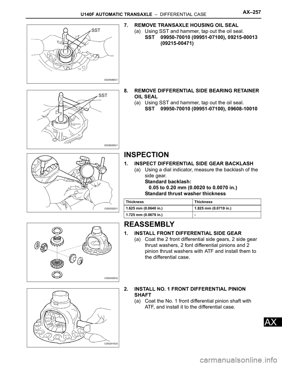
7. REMOVE TRANSAXLE HOUSING OIL SEAL
(a) Using SST and hammer, tap out the oil seal.
SST 09950-70010 (09951-07100), 09215-00013
(09215-00471)
8. REMOVE DIFFERENTIAL SIDE BEARING RETAINER
OIL SEAL
(a) Using SST and hammer, tap out the oil seal.
SST 09950-70010 (09951-07100), 09608-10010
INSPECTION
1. INSPECT DIFFERENTIAL SIDE GEAR BACKLASH
(a) Using a dial indicator, measure the backlash of the
side gear.
Standard backlash:
0.05 to 0.20 mm (0.0020 to 0.0070 in.)
Standard thrust washer thickness
REASSEMBLY
1. INSTALL FRONT DIFFERENTIAL SIDE GEAR
(a) Coat the 2 front differential side gears, 2 side gear
thrust washers, 2 font differential pinions and 2
pinion thrust washers with ATF and install them to
the differential case.
2. INSTALL NO. 1 FRONT DIFFERENTIAL PINION
SHAFT
(a) Coat the No. 1 front differential pinion shaft with
ATF, and install it to the differential case.
D025599E01
D025600E01
C050252E01
Thickness Thickness
1.625 mm (0.0640 in.) 1.825 mm (0.0719 in.)
1.725 mm (0.0679 in.) -
C050242E02
C050241E03
Page 1021 of 2000
U140F AUTOMATIC TRANSAXLE – DIFFERENTIAL CASEAX–261
AX
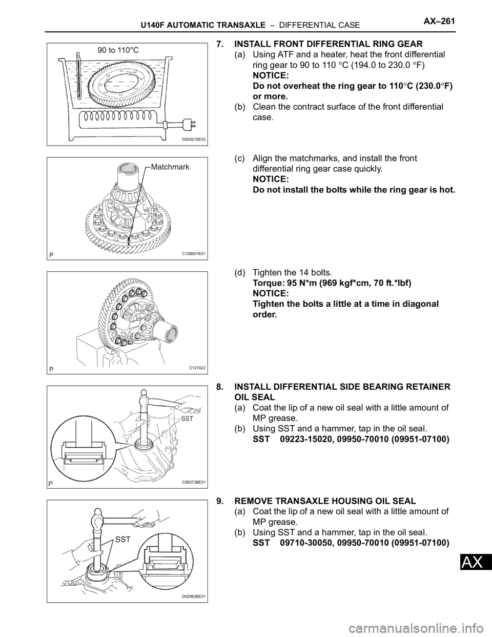
7. INSTALL FRONT DIFFERENTIAL RING GEAR
(a) Using ATF and a heater, heat the front differential
ring gear to 90 to 110
C (194.0 to 230.0 F)
NOTICE:
Do not overheat the ring gear to 110
C (230.0F)
or more.
(b) Clean the contract surface of the front differential
case.
(c) Align the matchmarks, and install the front
differential ring gear case quickly.
NOTICE:
Do not install the bolts while the ring gear is hot.
(d) Tighten the 14 bolts.
Torque: 95 N*m (969 kgf*cm, 70 ft.*lbf)
NOTICE:
Tighten the bolts a little at a time in diagonal
order.
8. INSTALL DIFFERENTIAL SIDE BEARING RETAINER
OIL SEAL
(a) Coat the lip of a new oil seal with a little amount of
MP grease.
(b) Using SST and a hammer, tap in the oil seal.
SST 09223-15020, 09950-70010 (09951-07100)
9. REMOVE TRANSAXLE HOUSING OIL SEAL
(a) Coat the lip of a new oil seal with a little amount of
MP grease.
(b) Using SST and a hammer, tap in the oil seal.
SST 09710-30050, 09950-70010 (09951-07100)
D025215E03
C126601E01
C127422
C083738E01
D025606E01