Page 6 of 2000
ENGINE - 2AZ-FE ENGINE
01MEG01Y
Taper Squish Shape : Resin Coating
240EG45
Plastic Region Tightening BoltsEG-9
5. Piston
The piston is made of aluminum alloy and skirt area is made compact and lightweight.
The piston head portion uses a taper squish shape to improve the fuel combustion efficiency.
The piston skirt has been coated with resin to reduce the friction loss.
6. Connecting Rod
The connecting rods and caps are made of
high-strength steel for weight reduction.
Nut-less type plastic region tightening bolts are
used on the connecting rod for a lighter design.
The connecting rod bearings are reduced in
width to reduce friction.
Page 71 of 2000
ENGINE - 2GR-FE ENGINE
285EG10 285EG09
60
Knock Sensor Bosses
36.6 mm
(1.441 in.)
105.5 mm
(4.15 in.)
View from Top Side
285EG11
Wa t e r P a s s a g eEG-75
4. Cylinder Block
The cylinder block is made of aluminum alloy, so it is lightweight.
The cylinder block has a bank angle of 60, a bank offset of 36.6 mm (1.441 in.) and a bore pitch of 105.5
mm (4.15 in.), resulting in a compact block in its length and width even for its displacement.
Installation bosses of the two knock sensors are located on the inside of left and right banks.
A water passage has been provided between the cylinder bores. By allowing the engine coolant to flow
between the cylinder bores, this construction enables the temperature of the cylinder walls to be kept
uniform.
Page 73 of 2000

ENGINE - 2GR-FE ENGINE
285EG14
Knock Pin
Plastic Region
Tightening Bolts
285EG15
Balance Weight
Engine
Front
No. 1 Journal
No. 2 Journal
No. 3 JournalNo. 4 JournalEG-77
6. Connecting Rod and Connecting Rod Bearing
Connecting rods that have been forged for high strength are used for weight reduction.
Knock pins are used at the mating surfaces of the bearing caps of the connecting rod to minimize the
shifting of the bearing caps during assembly.
The connecting rods and caps are made of high-strength steel for weight reduction.
Nutless-type plastic region tightening bolts are used on the connecting rods for a lighter design.
An aluminum bearing is used for the connecting rod bearings.
The connecting rod bearings are reduced in width to reduce friction.
7. Crankshaft
A crankshaft made of forged steel, which excels in rigidity and wear resistance, is used.
The crankshaft has 4 journals and 5 balance weights.
All pin and journal fillets are IH-finished to maintain adequate strength.
Page 333 of 2000
PREPARATION – SUPPLEMENTAL RESTRAINT SYSTEMPP–85
PP
EQUIPMENT
Bolt
Length: 35.0 mm (1.378 in.)
Pitch: 1.0 mm (0.039 in.)
Diameter: 6.0 mm (0.236 in.)Airbag disposal
Plastic bag Airbag disposal
Tire
Width: 185 mm (7.28 in.)
Inner diameter: 360 mm (14.17 in.)Airbag disposal
Tire with disc wheel
Width: 185 mm (7.28 in.)
Inner diameter: 360 mm (14.17 in.)Airbag disposal
Torque wrench -
Page 610 of 2000

EM–662AZ-FE ENGINE MECHANICAL – CYLINDER HEAD
EM
INSPECTION
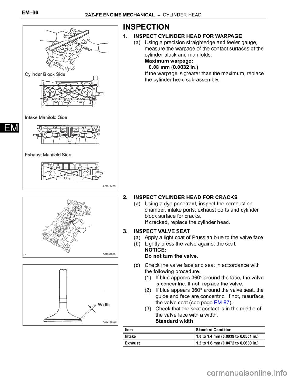
1. INSPECT CYLINDER HEAD FOR WARPAGE
(a) Using a precision straightedge and feeler gauge,
measure the warpage of the contact surfaces of the
cylinder block and manifolds.
Maximum warpage:
0.08 mm (0.0032 in.)
If the warpage is greater than the maximum, replace
the cylinder head sub-assembly.
2. INSPECT CYLINDER HEAD FOR CRACKS
(a) Using a dye penetrant, inspect the combustion
chamber, intake ports, exhaust ports and cylinder
block surface for cracks.
If cracked, replace the cylinder head.
3. INSPECT VALVE SEAT
(a) Apply a light coat of Prussian blue to the valve face.
(b) Lightly press the valve against the seat.
NOTICE:
Do not turn the valve.
(c) Check the valve face and seat in accordance with
the following procedure.
(1) If blue appears 360
around the face, the valve
is concentric. If not, replace the valve.
(2) If blue appears 360
around the valve seat, the
guide and face are concentric. If not, resurface
the valve seat (see page EM-87).
(3) Check that the seat contact is in the middle of
the valve face with a width.
Standard width
A098134E01
A013365E01
A062786E02
Item Standard Condition
Intake 1.0 to 1.4 mm (0.0039 to 0.0551 in.)
Exhaust 1.2 to 1.6 mm (0.0472 to 0.0630 in.)
Page 632 of 2000
EM–882AZ-FE ENGINE MECHANICAL – CYLINDER HEAD
EM
47. CHECK FOR ENGINE OIL LEAKS
48. CHECK FOR EXHAUST GAS LEAKS
49. INSPECT IGNITION TIMING (See page EM-1)
50. INSPECT ENGINE IDLING SPEED (See page EM-2)
51. INSPECT COMPRESSION (See page EM-3)
52. INSPECT CO/HC (See page EM-4)
53. INSTALL NO. 1 ENGINE COVER (See page EM-43)
54. INSTALL FRONT FENDER APRON RH
55. INSTALL NO. 1 ENGINE UNDER COVER
56. INSTALL FRONT WHEEL RH
57. INSTALL RADIATOR SUPPORT OPENING COVER
REPAIR
1. REPAIR VALVE SEATS
(a) If the seating is too high on the valve face, use 30
and 45
cutters to correct the seat.
(b) If the seating is too low on the valve face, use 75
and 45
cutters to correct the seat.
Standard width
(c) Lap the valve and valve seat by hand with an
abrasive compound.
(d) Recheck the valve seating position.
A128227E01
Item Standard Condition
Intake 1.0 to 1.4 mm (0.0394 to 0.0551 in.)
Exhaust 1.2 to 1.6 mm (0.0427 to 0.0630 in.)
Page 724 of 2000

2GR-FE ENGINE MECHANICAL – ENGINE UNITEM–87
EM
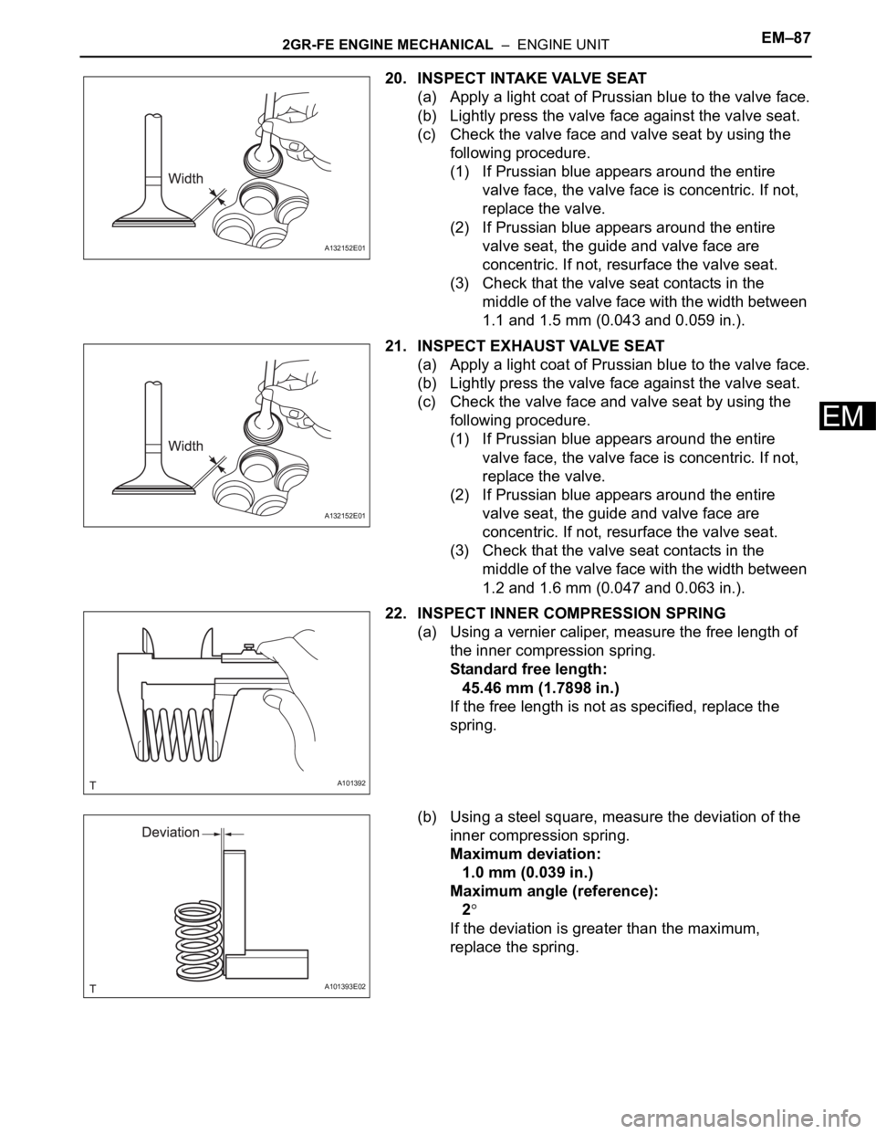
20. INSPECT INTAKE VALVE SEAT
(a) Apply a light coat of Prussian blue to the valve face.
(b) Lightly press the valve face against the valve seat.
(c) Check the valve face and valve seat by using the
following procedure.
(1) If Prussian blue appears around the entire
valve face, the valve face is concentric. If not,
replace the valve.
(2) If Prussian blue appears around the entire
valve seat, the guide and valve face are
concentric. If not, resurface the valve seat.
(3) Check that the valve seat contacts in the
middle of the valve face with the width between
1.1 and 1.5 mm (0.043 and 0.059 in.).
21. INSPECT EXHAUST VALVE SEAT
(a) Apply a light coat of Prussian blue to the valve face.
(b) Lightly press the valve face against the valve seat.
(c) Check the valve face and valve seat by using the
following procedure.
(1) If Prussian blue appears around the entire
valve face, the valve face is concentric. If not,
replace the valve.
(2) If Prussian blue appears around the entire
valve seat, the guide and valve face are
concentric. If not, resurface the valve seat.
(3) Check that the valve seat contacts in the
middle of the valve face with the width between
1.2 and 1.6 mm (0.047 and 0.063 in.).
22. INSPECT INNER COMPRESSION SPRING
(a) Using a vernier caliper, measure the free length of
the inner compression spring.
Standard free length:
45.46 mm (1.7898 in.)
If the free length is not as specified, replace the
spring.
(b) Using a steel square, measure the deviation of the
inner compression spring.
Maximum deviation:
1.0 mm (0.039 in.)
Maximum angle (reference):
2
If the deviation is greater than the maximum,
replace the spring.
A132152E01
A132152E01
A101392
A101393E02
Page 745 of 2000
EM–1082GR-FE ENGINE MECHANICAL – ENGINE UNIT
EM
(c) Position the piston rings so that the ring ends are as
shown in the illustration.
NOTICE:
Do not align the ring ends.
5. INSTALL CRANKSHAFT BEARING
NOTICE:
Main bearings come in widths between 18.0 mm
(0.709 in.) and 21.0 mm (0.827 in.). Install the 21.0
mm (0.827 in.) bearings in the No. 1 and No. 4
cylinder block journal positions with the main
bearing cap. Install the 18.0 mm (0.709 in.) bearings
in the No. 2 and No. 3 positions.
(a) Clean the main journal and both surfaces of the
bearing.
(b) Install the upper bearing.
(1) Install the upper bearing to the cylinder block
as shown in the illustration.
NOTICE:
Do not apply engine oil to the bearing and
its contact surface.
A131881E02
A131973E01
A132043E01