Page 1351 of 2000

GF1A TRANSFER – ACTIVE TORQUE CONTROL 4WD SYSTEMTF–23
TF
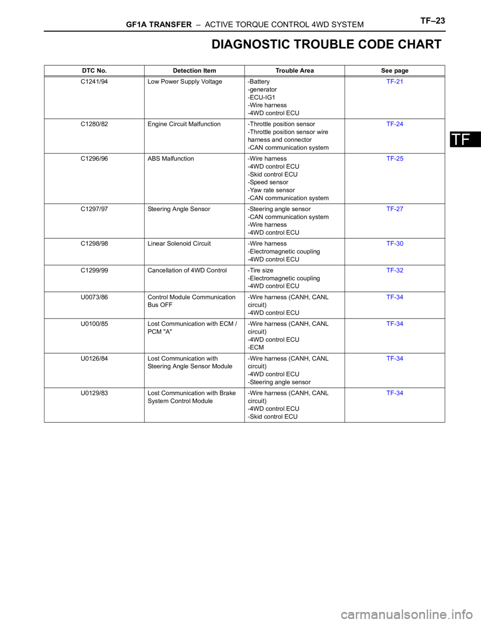
DIAGNOSTIC TROUBLE CODE CHART
DTC No. Detection Item Trouble Area See page
C1241/94 Low Power Supply Voltage -Battery
-generator
-ECU-IG1
-Wire harness
-4WD control ECUTF-21
C1280/82 Engine Circuit Malfunction -Throttle position sensor
-Throttle position sensor wire
harness and connector
-CAN communication systemTF-24
C1296/96 ABS Malfunction -Wire harness
-4WD control ECU
-Skid control ECU
-Speed sensor
-Yaw rate sensor
-CAN communication systemTF-25
C1297/97 Steering Angle Sensor -Steering angle sensor
-CAN communication system
-Wire harness
-4WD control ECUTF-27
C1298/98 Linear Solenoid Circuit -Wire harness
-Electromagnetic coupling
-4WD control ECUTF-30
C1299/99 Cancellation of 4WD Control -Tire size
-Electromagnetic coupling
-4WD control ECUTF-32
U0073/86 Control Module Communication
Bus OFF-Wire harness (CANH, CANL
circuit)
-4WD control ECUTF-34
U0100/85 Lost Communication with ECM /
PCM "A"-Wire harness (CANH, CANL
circuit)
-4WD control ECU
-ECMTF-34
U0126/84 Lost Communication with
Steering Angle Sensor Module-Wire harness (CANH, CANL
circuit)
-4WD control ECU
-Steering angle sensorTF-34
U0129/83 Lost Communication with Brake
System Control Module-Wire harness (CANH, CANL
circuit)
-4WD control ECU
-Skid control ECUTF-34
Page 1426 of 2000

DF–22DIFFERENTIAL – REAR DIFFERENTIAL CARRIER ASSEMBLY
DF
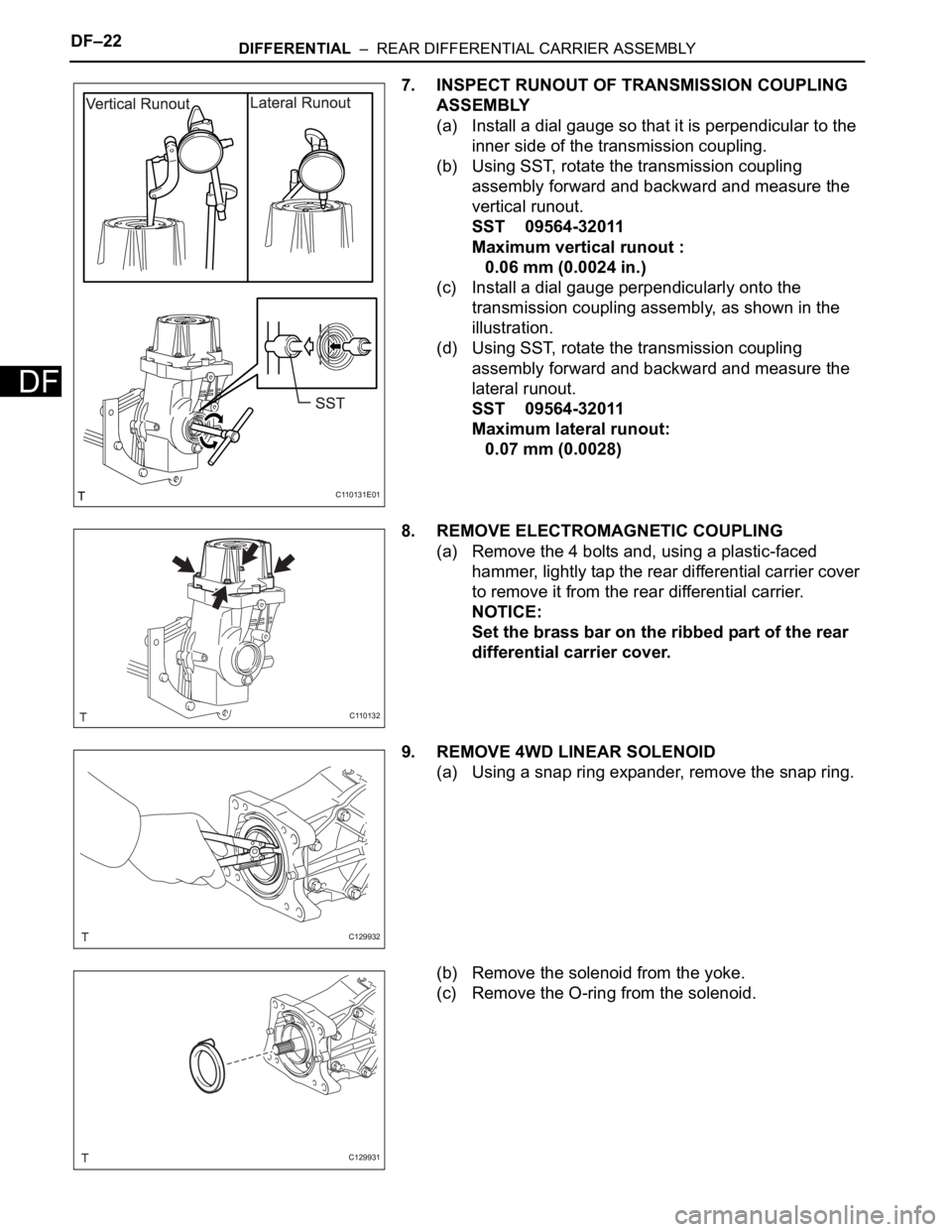
7. INSPECT RUNOUT OF TRANSMISSION COUPLING
ASSEMBLY
(a) Install a dial gauge so that it is perpendicular to the
inner side of the transmission coupling.
(b) Using SST, rotate the transmission coupling
assembly forward and backward and measure the
vertical runout.
SST 09564-32011
Maximum vertical runout :
0.06 mm (0.0024 in.)
(c) Install a dial gauge perpendicularly onto the
transmission coupling assembly, as shown in the
illustration.
(d) Using SST, rotate the transmission coupling
assembly forward and backward and measure the
lateral runout.
SST 09564-32011
Maximum lateral runout:
0.07 mm (0.0028)
8. REMOVE ELECTROMAGNETIC COUPLING
(a) Remove the 4 bolts and, using a plastic-faced
hammer, lightly tap the rear differential carrier cover
to remove it from the rear differential carrier.
NOTICE:
Set the brass bar on the ribbed part of the rear
differential carrier cover.
9. REMOVE 4WD LINEAR SOLENOID
(a) Using a snap ring expander, remove the snap ring.
(b) Remove the solenoid from the yoke.
(c) Remove the O-ring from the solenoid.
C110131E01
C110132
C129932
C129931
Page 1427 of 2000
DIFFERENTIAL – REAR DIFFERENTIAL CARRIER ASSEMBLYDF–23
DF
10. REMOVE YOKE
(a) Using a 5 mm socket hexagon wrench, remove the
3 bolts and yoke from the differential carrier.
11. REMOVE TRANSMISSION COUPLING CONICAL
SPRING WASHER
(a) Remove the spring washer from the differential
carrier.
12. REMOVE TRANSMISSION COUPLING SHIM
(a) Remove the shim from the differential carrier.
13. INSPECT DIFFERENTIAL RING GEAR BACKLASH
(a) Insert a dial gauge through the rear differential
carrier cover plug hole, and set it perpendicular to
the ring gear tooth surface's tip.
(b) Using SST, fix the drive pinion in place.
SST 09556-16011
(c) Using SST, rotate the rear differential case forward
and backward, and measure the backlash.
SST 09564-32011
Standard backlash:
0.09 to 0.16 mm (0.0034 to 0.0063 in.)
NOTICE:
Measure at 3 or more areas around the
circumference of the ring gear.
C129930
C109021E01
C109022E01
C110134E01
Page 1457 of 2000

AXLE – REAR AXLE HUB AND BEARINGAH–17
AH
REMOVAL
1. REMOVE REAR WHEEL
2. DISCONNECT CABLE FROM NEGATIVE BATTERY
TERMINAL
CAUTION:
Wait at least 90 seconds after disconnecting the
cable from the negative (-) battery terminal to
prevent airbag and seat belt pretensioner activation.
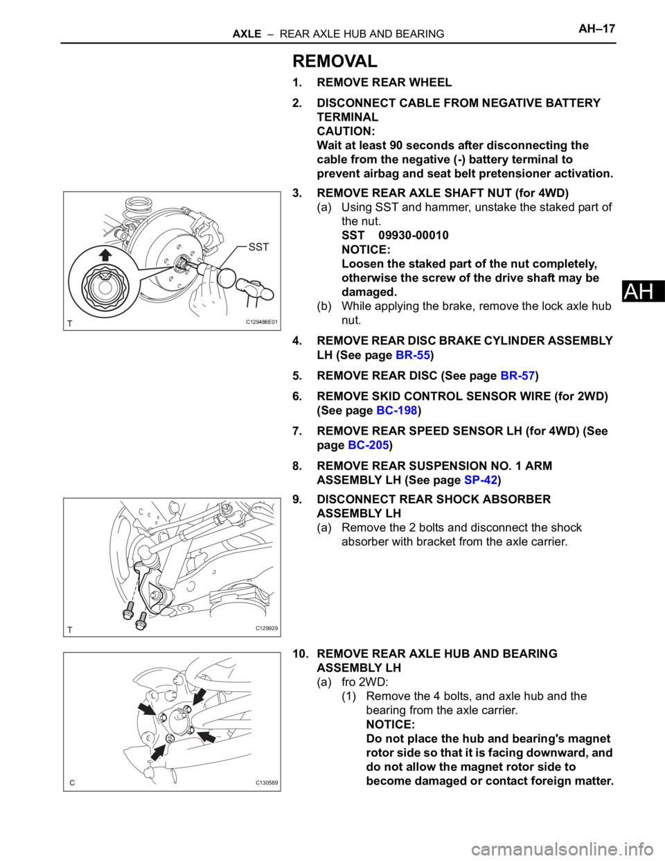
3. REMOVE REAR AXLE SHAFT NUT (for 4WD)
(a) Using SST and hammer, unstake the staked part of
the nut.
SST 09930-00010
NOTICE:
Loosen the staked part of the nut completely,
otherwise the screw of the drive shaft may be
damaged.
(b) While applying the brake, remove the lock axle hub
nut.
4. REMOVE REAR DISC BRAKE CYLINDER ASSEMBLY
LH (See page BR-55)
5. REMOVE REAR DISC (See page BR-57)
6. REMOVE SKID CONTROL SENSOR WIRE (for 2WD)
(See page BC-198)
7. REMOVE REAR SPEED SENSOR LH (for 4WD) (See
page BC-205)
8. REMOVE REAR SUSPENSION NO. 1 ARM
ASSEMBLY LH (See page SP-42)
9. DISCONNECT REAR SHOCK ABSORBER
ASSEMBLY LH
(a) Remove the 2 bolts and disconnect the shock
absorber with bracket from the axle carrier.
10. REMOVE REAR AXLE HUB AND BEARING
ASSEMBLY LH
(a) fro 2WD:
(1) Remove the 4 bolts, and axle hub and the
bearing from the axle carrier.
NOTICE:
Do not place the hub and bearing's magnet
rotor side so that it is facing downward, and
do not allow the magnet rotor side to
become damaged or contact foreign matter.
C129486E01
C129929
C130589