Page 1563 of 2000

BC–60BRAKE CONTROL – VEHICLE STABILITY CONTROL SYSTEM
BC
2. PARFORM ACTIVE TEST
HINT:
Performing the intelligent tester's ACTIVE TEST allows
relay, VSV, actuator and other items to be operated
without removing any parts. Performing the ACTIVE
TEST early in troubleshooting is one way to save time.
The DATA LIST can be displayed during the ACTIVE
TEST.
(a) Connect the intelligent tester (with CAN VIM) to the
DLC3.
(b) Turn the ignition switch ON.
(c) Turn the intelligent tester on.
(d) Perform the ACTIVE TEST according to the display
on the tester.
HINT:
• The ignition switch must be turned ON to
proceed to the ACTIVE TEST using the
intelligent tester.
• The ACTIVE TESTs of the ABS solenoid, ABS
motor relay, ABS warning light and BRAKE
warning light are available when the vehicle is
stopped.
• The motors stop automatically after 5 seconds of
activation to prevent them from being damaged.
When the motors are driven repeatedly, certain
intervals are required.
• Each solenoid stops automatically after 2
seconds of activation to prevent them from being
damaged, and can be operated again after a
certain interval.
• Do not depress the brake pedal while only the
pressure reduction solenoid valves are on.
• Do not drive 2 or more solenoids simultaneously
except to operate the pressure holding solenoid
valves and pressure reduction solenoid valves of
each wheel.
Skid control ECU
Tester Display Test Part Control Range
ABS WARN LAMP Turns ABS warning light ON / OFF Observe combination meter
VSC WARN LAMP Turns VSC warning light ON / OFF Observe combination meter
BRAKE WARN LAMP Turns Brake warning light ON / OFF Observe combination meter
SLIP INDI LAMP Turns Slip indicator light ON / OFF Observe combination meter
D-HILL LIGHT*1 Turns downhill assist control indicator light ON /
OFFObserve combination meter
AUTO LSD LAMP*2 Turns AUTO LSD indicator light ON / OFF Observe combination meter
BUZZER Turns skid control buzzer ON / OFF Buzzer can be heard
STP LAMP RELAY Turns stop light relay (BRK relay) ON / OFF Operation sound of motor can be heard
SOL RELAY Turns ABS solenoid relay ON / OFF -
MOTOR RELAY Turns ABS motor relay ON / OFF Operation sound of motor can be heard
SRLR Turns ABS solenoid (SRLR) ON / OFF Operation sound of solenoid (clicking sound)
can be heard
SRLH Turns ABS solenoid (SRLH) ON / OFF Operation sound of solenoid (clicking sound)
can be heard
Page 1574 of 2000
BRAKE – BRAKE MASTER CYLINDERBR–21
BR
ON-VEHICLE INSPECTION
1. CHECK BRAKE FLUID LEVEL WARNING SWITCH
(a) Remove the reservoir filler cap and strainer.
(b) Disconnect the brake fluid level warning switch
connector.
(c) Measure the resistance of the switch.
HINT:
There is a float inside the reservoir. Its position can
be changed by increasing or decreasing the brake
fluid level.
Standard resistance
If the value is not as specified, replace the brake
master cylinder reservoir sub-assembly.
(d) Add brake fluid to the MAX level.
C129064
Tester Connection Condition Specified Condition
1 - 2 Float up (Switch OFF) 10 k
or higher
1 - 2 Float down (Switch ON) Below 1
Page 1575 of 2000
BR–22BRAKE – BRAKE MASTER CYLINDER
BR
REMOVAL
(2005/11-2006/01)
NOTICE:
• The master cylinder and piston are designed so that
the piston can easily fall out. Prevent this by making
sure that the tip of the master cylinder points
downward when handling the master cylinder.
• Make sure foreign matter does not attach to the
master cylinder's piston. If foreign matter attaches,
clean it off with a cloth. Then apply lithium soap base
glycol grease to the entire outer circumference
contact surface area of the piston.
1. REMOVE AIR CLEANER CASE SUB-ASSEMBLY
(a) Remove the air cleaner case (see page EM-98).
HINT:
Refer to the procedures from the removal of the
purge VSV up until the removal of the air cleaner
case.
2. DRAIN BRAKE FLUID
NOTICE:
Wash off brake fluid immediately if it comes in
contact with any painted surface.
3. REMOVE BRAKE MASTER CYLINDER SUB-
ASSEMBLY
(a) Release the vacuum pressure in the brake booster
as follows.
(1) Stop the engine.
(2) Depress the brake pedal several times.
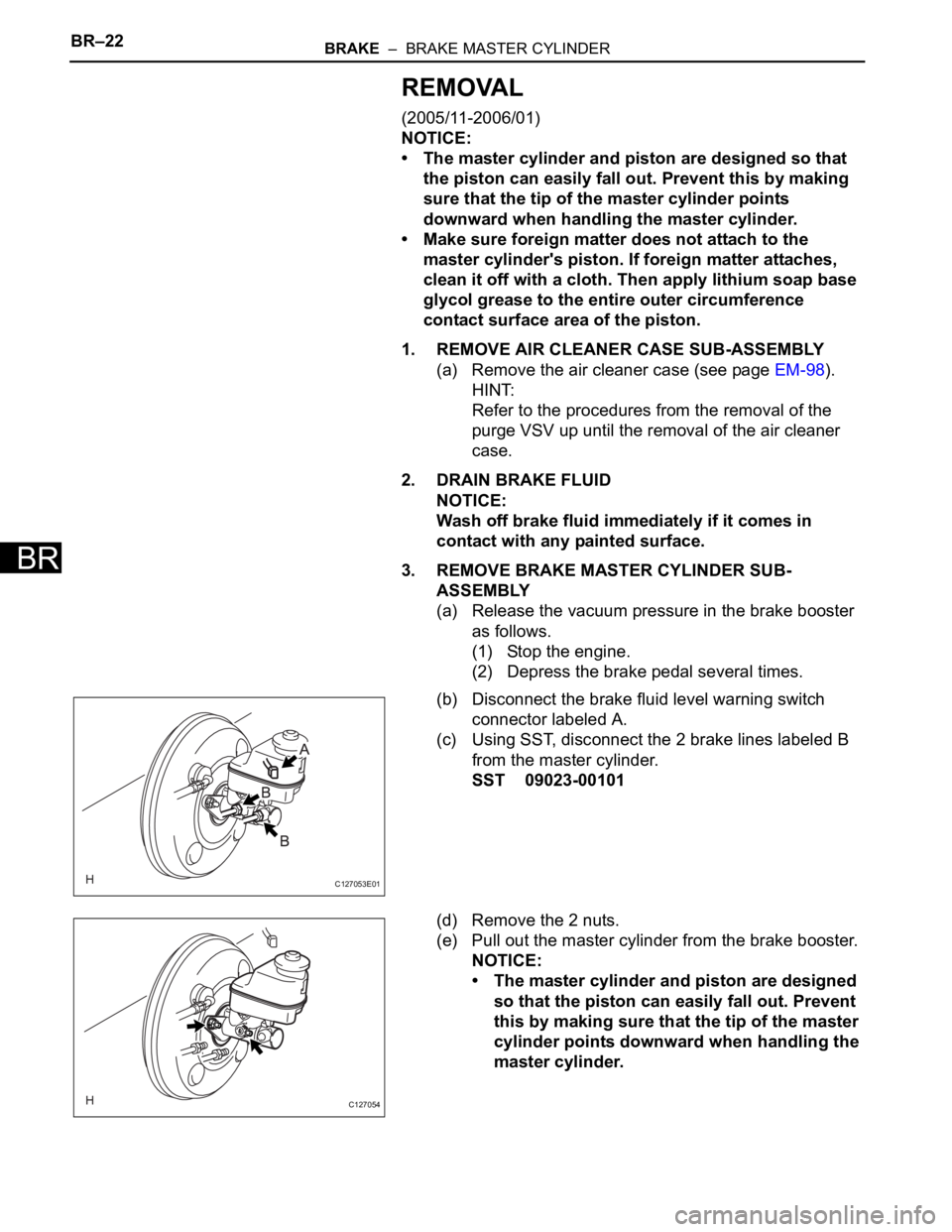
(b) Disconnect the brake fluid level warning switch
connector labeled A.
(c) Using SST, disconnect the 2 brake lines labeled B
from the master cylinder.
SST 09023-00101
(d) Remove the 2 nuts.
(e) Pull out the master cylinder from the brake booster.
NOTICE:
• The master cylinder and piston are designed
so that the piston can easily fall out. Prevent
this by making sure that the tip of the master
cylinder points downward when handling the
master cylinder.
C127053E01
C127054
Page 1577 of 2000
BR–24BRAKE – BRAKE MASTER CYLINDER
BR
REMOVAL
(2006/01- )
NOTICE:
• The master cylinder and piston are designed so that
the piston can easily fall out. Prevent this by making
sure that the tip of the master cylinder points
downward when handling the master cylinder.
• Make sure foreign matter does not attach to the
master cylinder's piston. If foreign matter attaches,
clean it off with a cloth. Then apply lithium soap base
glycol grease to the entire outer circumference
contact surface area of the piston.
1. REMOVE AIR CLEANER CASE SUB-ASSEMBLY (for
2AZ-FE)
(a) Remove the air cleaner case (see page EM-98).
HINT:
Refer to the procedures from the removal of the
purge VSV up until the removal of the air cleaner
case.
2. REMOVE AIR CLEANER CASE (for 2GR-FE)
(a) Remove the air cleaner case (see page EM-21).
HINT:
Refer to the procedures from the removal of the air
cleaner cap sub-assembly up until the removal of
the air cleaner case.
3. DRAIN BRAKE FLUID
NOTICE:
Wash off brake fluid immediately if it comes in
contact with any painted surface.
4. REMOVE BRAKE MASTER CYLINDER SUB-
ASSEMBLY
(a) Release the vacuum pressure in the brake booster
as follows.
(1) Stop the engine.
(2) Depress the brake pedal several times.
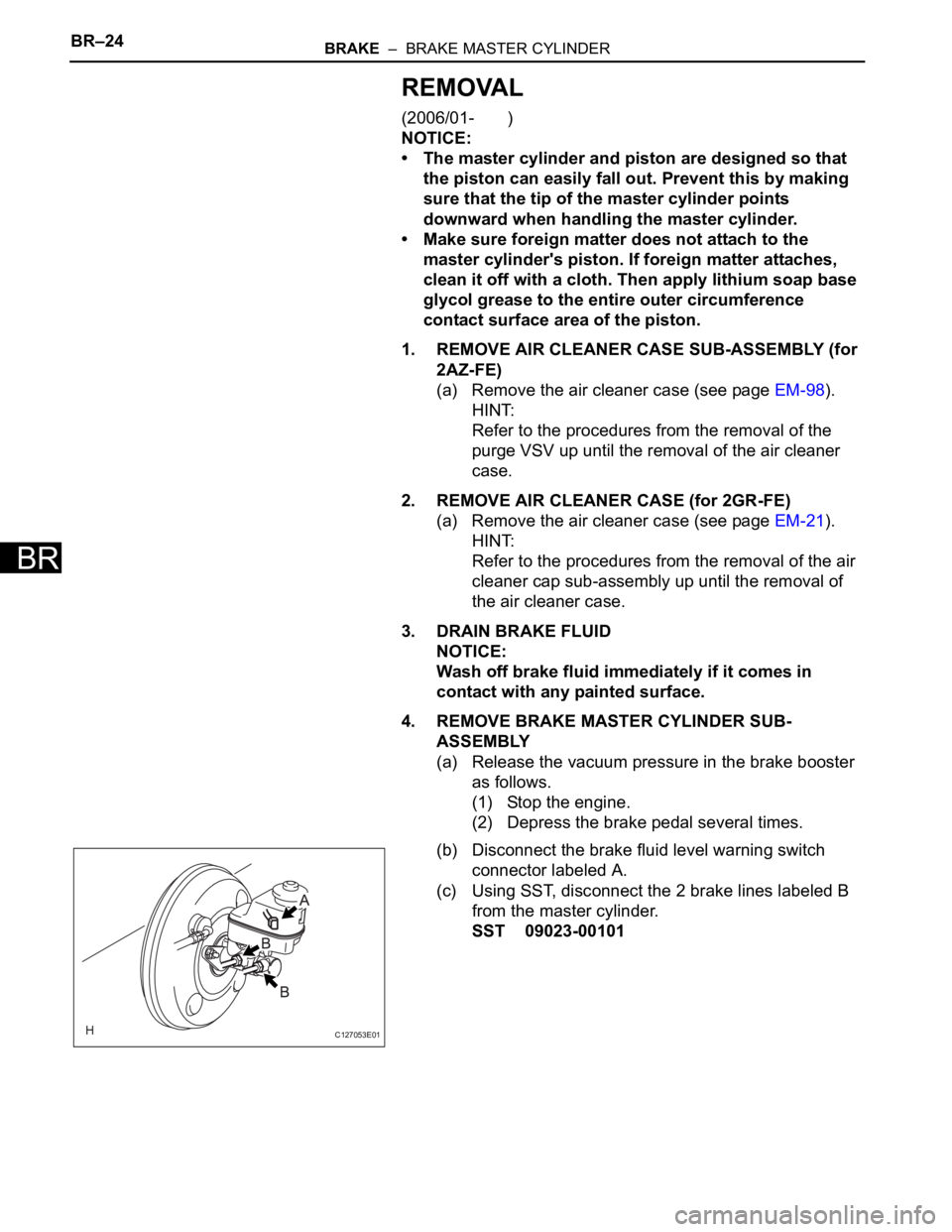
(b) Disconnect the brake fluid level warning switch
connector labeled A.
(c) Using SST, disconnect the 2 brake lines labeled B
from the master cylinder.
SST 09023-00101
C127053E01
Page 1582 of 2000
BRAKE – BRAKE MASTER CYLINDERBR–29
BR
INSTALLATION
(2005/11-2006/01)
1. INSTALL BRAKE MASTER CYLINDER SUB-
ASSEMBLY
NOTICE:
• The master cylinder and piston are designed so
that the piston can easily fall out. Prevent this by
making sure that the tip of the master cylinder
points downward when handling the master
cylinder.
• Make sure foreign matter does not attach to the
master cylinder's piston. If foreign matter
attaches, clean it off with a cloth. Then apply
lithium soap base glycol grease to the entire outer
circumference contact surface area of the piston.
(a) Install a new O-ring to the master cylinder.
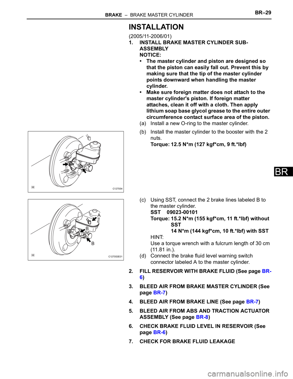
(b) Install the master cylinder to the booster with the 2
nuts.
Torque: 12.5 N*m (127 kgf*cm, 9 ft.*lbf)
(c) Using SST, connect the 2 brake lines labeled B to
the master cylinder.
SST 09023-00101
Torque: 15.2 N*m (155 kgf*cm, 11 ft.*lbf) without
SST
14 N*m (144 kgf*cm, 10 ft.*lbf) with SST
HINT:
Use a torque wrench with a fulcrum length of 30 cm
(11.81 in.).
(d) Connect the brake fluid level warning switch
connector labeled A to the master cylinder.
2. FILL RESERVOIR WITH BRAKE FLUID (See page BR-
6)
3. BLEED AIR FROM BRAKE MASTER CYLINDER (See
page BR-7)
4. BLEED AIR FROM BRAKE LINE (See page BR-7)
5. BLEED AIR FROM ABS AND TRACTION ACTUATOR
ASSEMBLY (See page BR-8)
6. CHECK BRAKE FLUID LEVEL IN RESERVOIR (See
page BR-6)
7. CHECK FOR BRAKE FLUID LEAKAGE
C127054
C127053E01
Page 1584 of 2000
BRAKE – BRAKE MASTER CYLINDERBR–31
BR
INSTALLATION
(2006/01- )
1. INSTALL BRAKE MASTER CYLINDER SUB-
ASSEMBLY
NOTICE:
• The master cylinder and piston are designed so
that the piston can easily fall out. Prevent this by
making sure that the tip of the master cylinder
points downward when handling the master
cylinder.
• Make sure foreign matter does not attach to the
master cylinder's piston. If foreign matter
attaches, clean it off with a cloth. Then apply
lithium soap base glycol grease to the entire outer
circumference contact surface area of the piston.
(a) Install a new O-ring to the master cylinder.
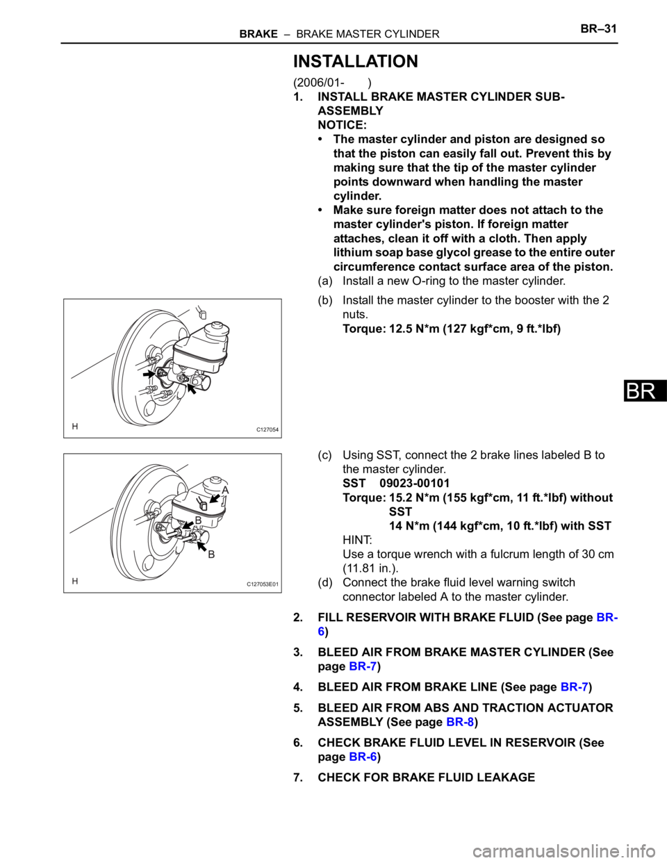
(b) Install the master cylinder to the booster with the 2
nuts.
Torque: 12.5 N*m (127 kgf*cm, 9 ft.*lbf)
(c) Using SST, connect the 2 brake lines labeled B to
the master cylinder.
SST 09023-00101
Torque: 15.2 N*m (155 kgf*cm, 11 ft.*lbf) without
SST
14 N*m (144 kgf*cm, 10 ft.*lbf) with SST
HINT:
Use a torque wrench with a fulcrum length of 30 cm
(11.81 in.).
(d) Connect the brake fluid level warning switch
connector labeled A to the master cylinder.
2. FILL RESERVOIR WITH BRAKE FLUID (See page BR-
6)
3. BLEED AIR FROM BRAKE MASTER CYLINDER (See
page BR-7)
4. BLEED AIR FROM BRAKE LINE (See page BR-7)
5. BLEED AIR FROM ABS AND TRACTION ACTUATOR
ASSEMBLY (See page BR-8)
6. CHECK BRAKE FLUID LEVEL IN RESERVOIR (See
page BR-6)
7. CHECK FOR BRAKE FLUID LEAKAGE
C127054
C127053E01
Page 1600 of 2000
SR–16STEERING COLUMN – STEERING COLUMN ASSEMBLY
SR
(c) Insert the tip of a screwdriver into the hole in the
steering column bracket and tilt it downward, as
shown in the illustration, to disengage the claw of
the ignition switch lock cylinder. Then pull out the
ignition switch lock cylinder.
4. REMOVE UNLOCK WARNING SWITCH ASSEMBLY
(a) Push up the unlock warning switch center portion to
disengage the 2 claws.
HINT:
Slide the unlock warning switch in the direction
shown by the arrow in the illustration to remove it.
5. REMOVE KEY INTERLOCK SOLENOID
(a) for Automatic Transaxle:
(1) Remove the 2 screws and remove the key
interlock solenoid from the steering column
bracket upper.
6. REMOVE IGNITION OR STARTER SWITCH
ASSEMBLY
(a) Detach the 2 claws and remove the ignition (starter)
switch from the steering column bracket upper.
C128809E02
C128810
C128811
C128812
Page 1601 of 2000
STEERING COLUMN – STEERING COLUMN ASSEMBLYSR–17
SR
INSPECTION
1. CHECK TORQUE SENSOR
(a) Check the torque sensor (see page PS-19).
2. CHECK POWER STEERING MOTOR
(a) Check the power steering motor (see page PS-22).
3. CHECK MOTOR ROTATION ANGLE SENSOR
(a) Check the motor rotation angle sensor (see page
PS-25).
REASSEMBLY
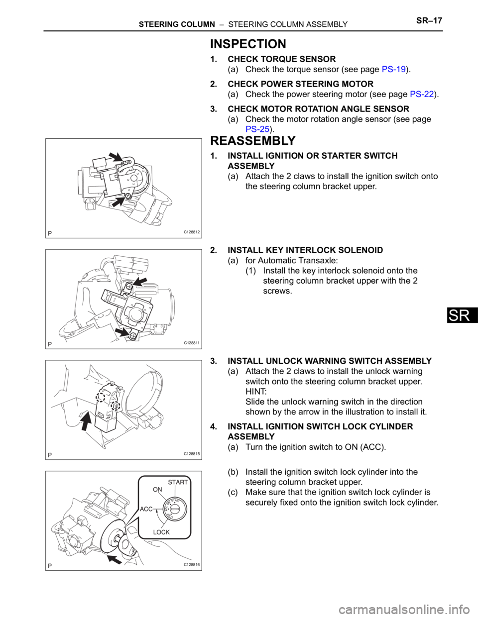
1. INSTALL IGNITION OR STARTER SWITCH
ASSEMBLY
(a) Attach the 2 claws to install the ignition switch onto
the steering column bracket upper.
2. INSTALL KEY INTERLOCK SOLENOID
(a) for Automatic Transaxle:
(1) Install the key interlock solenoid onto the
steering column bracket upper with the 2
screws.
3. INSTALL UNLOCK WARNING SWITCH ASSEMBLY
(a) Attach the 2 claws to install the unlock warning
switch onto the steering column bracket upper.
HINT:
Slide the unlock warning switch in the direction
shown by the arrow in the illustration to install it.
4. INSTALL IGNITION SWITCH LOCK CYLINDER
ASSEMBLY
(a) Turn the ignition switch to ON (ACC).
(b) Install the ignition switch lock cylinder into the
steering column bracket upper.
(c) Make sure that the ignition switch lock cylinder is
securely fixed onto the ignition switch lock cylinder.
C128812
C128811
C128815
C128816