2006 TOYOTA RAV4 warning
[x] Cancel search: warningPage 1898 of 2000

WIPER AND WASHER – WIPER SWITCHWW–29
WW
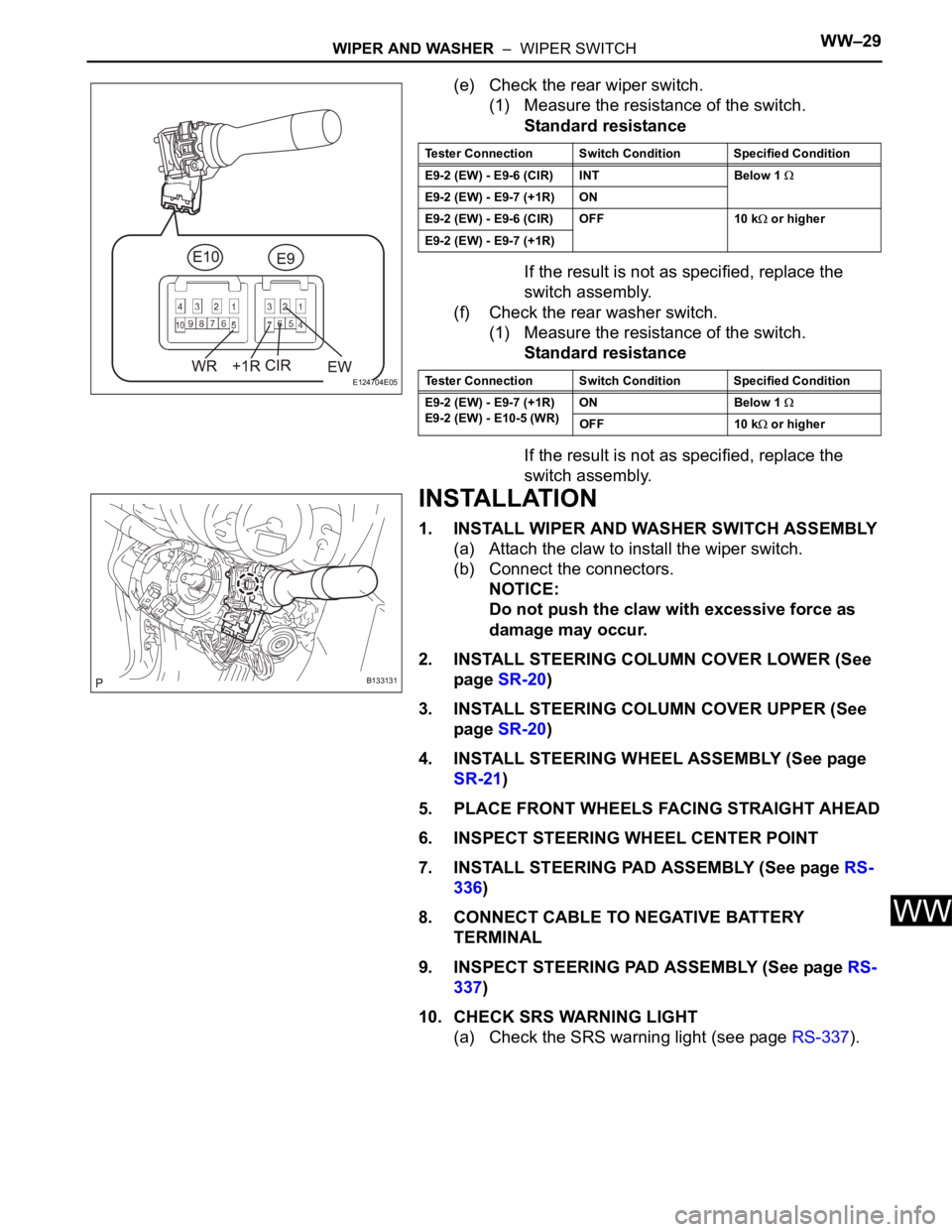
(e) Check the rear wiper switch.
(1) Measure the resistance of the switch.
Standard resistance
If the result is not as specified, replace the
switch assembly.
(f) Check the rear washer switch.
(1) Measure the resistance of the switch.
Standard resistance
If the result is not as specified, replace the
switch assembly.
INSTALLATION
1. INSTALL WIPER AND WASHER SWITCH ASSEMBLY
(a) Attach the claw to install the wiper switch.
(b) Connect the connectors.
NOTICE:
Do not push the claw with excessive force as
damage may occur.
2. INSTALL STEERING COLUMN COVER LOWER (See
page SR-20)
3. INSTALL STEERING COLUMN COVER UPPER (See
page SR-20)
4. INSTALL STEERING WHEEL ASSEMBLY (See page
SR-21)
5. PLACE FRONT WHEELS FACING STRAIGHT AHEAD
6. INSPECT STEERING WHEEL CENTER POINT
7. INSTALL STEERING PAD ASSEMBLY (See page RS-
336)
8. CONNECT CABLE TO NEGATIVE BATTERY
TERMINAL
9. INSPECT STEERING PAD ASSEMBLY (See page RS-
337)
10. CHECK SRS WARNING LIGHT
(a) Check the SRS warning light (see page RS-337).
E124704E05
Tester Connection Switch Condition Specified Condition
E9-2 (EW) - E9-6 (CIR) INT Below 1
E9-2 (EW) - E9-7 (+1R) ON
E9-2 (EW) - E9-6 (CIR) OFF 10 k
or higher
E9-2 (EW) - E9-7 (+1R)
Tester Connection Switch Condition Specified Condition
E9-2 (EW) - E9-7 (+1R)
E9-2 (EW) - E10-5 (WR)ON Below 1
OFF 10 k or higher
B133131
Page 1905 of 2000

DOOR LOCK – POWER DOOR LOCK CONTROL SYSTEMDL–9
DL
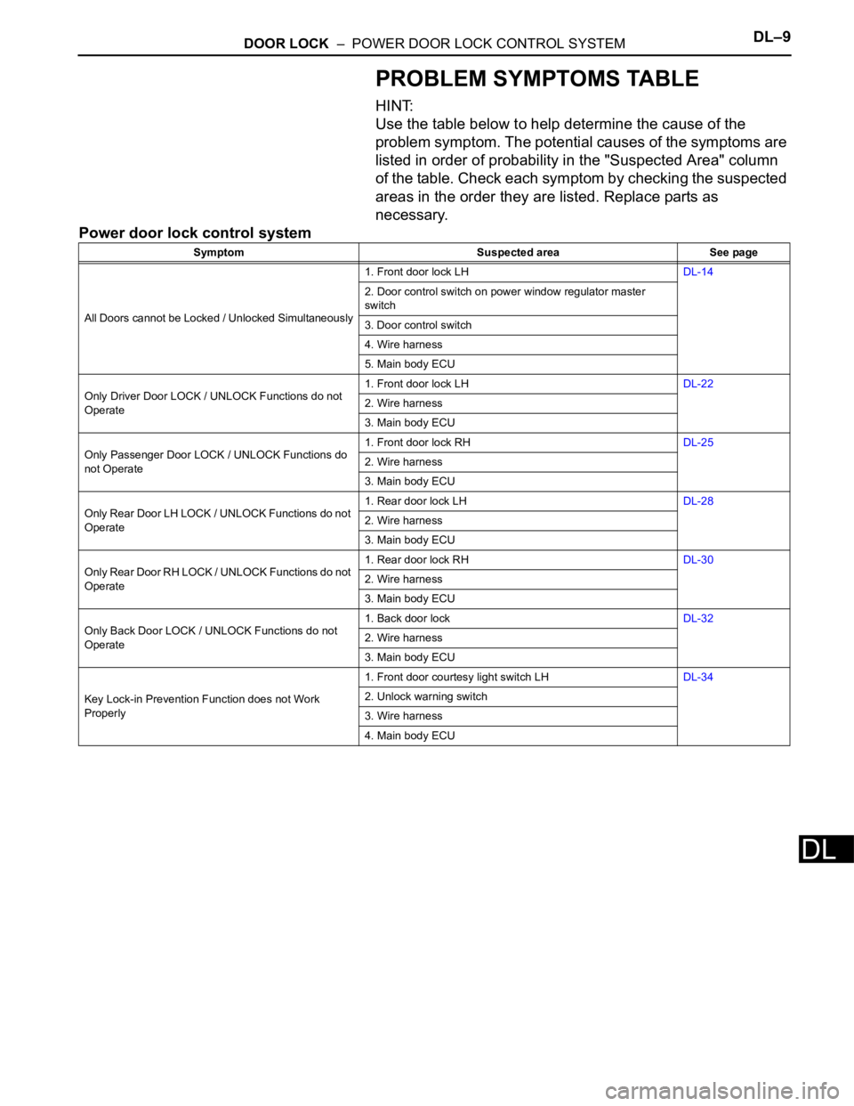
PROBLEM SYMPTOMS TABLE
HINT:
Use the table below to help determine the cause of the
problem symptom. The potential causes of the symptoms are
listed in order of probability in the "Suspected Area" column
of the table. Check each symptom by checking the suspected
areas in the order they are listed. Replace parts as
necessary.
Power door lock control system
Symptom Suspected area See page
All Doors cannot be Locked / Unlocked Simultaneously1. Front door lock LHDL-14
2. Door control switch on power window regulator master
switch
3. Door control switch
4. Wire harness
5. Main body ECU
Only Driver Door LOCK / UNLOCK Functions do not
Operate1. Front door lock LHDL-22
2. Wire harness
3. Main body ECU
Only Passenger Door LOCK / UNLOCK Functions do
not Operate1. Front door lock RHDL-25
2. Wire harness
3. Main body ECU
Only Rear Door LH LOCK / UNLOCK Functions do not
Operate1. Rear door lock LHDL-28
2. Wire harness
3. Main body ECU
Only Rear Door RH LOCK / UNLOCK Functions do not
Operate1. Rear door lock RHDL-30
2. Wire harness
3. Main body ECU
Only Back Door LOCK / UNLOCK Functions do not
Operate1. Back door lockDL-32
2. Wire harness
3. Main body ECU
Key Lock-in Prevention Function does not Work
Properly1. Front door courtesy light switch LHDL-34
2. Unlock warning switch
3. Wire harness
4. Main body ECU
Page 1908 of 2000

DL–12DOOR LOCK – POWER DOOR LOCK CONTROL SYSTEM
DL
ACT+ (IH-17) - Body
groundR - Body ground Door lock motor drive lock
outputDriver side door control
switch or passenger side
door control switch or
driver side door key
cylinder OFFBelow 1 V
ACT+ (IH-17) - Body
groundR - Body ground Door lock motor drive lock
outputDriver side door control
switch or passenger side
door control switch or
driver side door key
cylinder ON (LOCK)10 to 14 V
Below 1 V
ACT- (IA-4) - Body ground BR- Body ground Door lock motor drive
unlock outputDriver side door control
switch or passenger side
door control switch or
driver side door key
cylinder OFFBelow 1 V
ACT- (IA-4) - Body ground BR - Body ground Door lock motor drive
unlock outputDriver side door control
switch or passenger side
door control switch or
driver side door key
cylinder ON (UNLOCK)10 to 14 V
Below 1 V
ACT- (IH-18) - Body
groundB - Body ground Door lock motor drive
unlock outputDriver side door control
switch or passenger side
door control switch or
driver side door key
cylinder OFFBelow 1 V
ACT- (IH-18) - Body
groundB - Body ground Door lock motor drive
unlock outputDriver side door control
switch or passenger side
door control switch or
driver side door key
cylinder ON (UNLOCK)10 to 14 V
Below 1 V
KSW (IE-26) - Body
groundL- Body ground Key unlock warning switch
inputKey is inserted in ignition
key cylinderBelow 1 V
KSW (IE-26) - Body
groundL- Body ground Key unlock warning switch
inputNo key is in ignition key
cylinder10 to 14 V
UL1 (IH-5) - Body ground B - Body ground Driver side manual unlock
switch inputDriver side door control
switch OFFBelow 1 V
UL1 (IH-5) - Body ground B - Body ground Driver side manual unlock
switch inputDriver side door control
switch ON (UNLOCK)10 to 14 V
Below 1 V
UL1 (IH-14) - Body ground O - Body ground Passenger side manual
unlock switch inputPassenger side door
control switch OFFBelow 1 V
UL1 (IH-14) - Body ground O - Body ground Passenger side manual
unlock switch inputPassenger side door
control switch ON
(UNLOCK)10 to 14 V
Below 1 V
L1 (IH-4) - Body ground P - Body ground Driver side manual lock
switch inputDriver side door control
switch OFFBelow 1 V
L1 (IH-4) - Body ground P - Body ground Driver side manual lock
switch inputDriver side door control
switch ON (LOCK)10 to 14 V
Below 1 V
L1 (IH-13) - Body ground V - Body ground Passenger side manual
lock switch inputPassenger side door
control switch OFFBelow 1 V
L1 (IH-13) - Body ground V - Body ground Passenger side manual
lock switch inputPassenger side door
control switch ON (LOCK)10 to 14 V
Below 1 V
L2 (IH-7) - Body ground SB - Body ground Driver side Key-linked
operated lock switch inputDriver side door key
cylinder OFFBelow 1 V
L2 (IH-7) - Body ground SB - Body ground Driver side Key-linked
operated lock switch inputDriver side door key
cylinder ON (LOCK)10 to 14 V
Below 1 V
PCTY (IC-14) - Body
groundBR - Body ground Passenger door courtesy
switch inputPassenger side door
closed10 to 14 V
PCTY (IC-14) - Body
groundBR - Body ground Passenger door courtesy
switch inputPassenger side door open Below 1 V
RRCY (ID-7) - Body
groundLC - Body ground Rear door courtesy switch
LH inputRear RH door closed 10 to 14 V Symbols (Terminal No.) Wiring Color Terminal Description ConditionSpecified Condition
Page 1911 of 2000

DOOR LOCK – POWER DOOR LOCK CONTROL SYSTEMDL–15
DL
DATA LIST / ACTIVE TEST
1. READ DATA LIST
HINT:
Using the intelligent tester's DATA LIST allows switch,
sensor, actuator and other item values to be read without
removing any parts. Reading the DATA LIST early in
troubleshooting is one way to save time.
(a) Connect the intelligent tester (with CAN VIM) to the
DLC3.
(b) Turn the ignition switch ON.
(c) Read the DATA LIST on the tester's screen.
Main body ECU
Item Measurement Item / Display
(Range)Normal Condition Diagnostic Note
D DOR CTY SW Driver side door courtesy light
switch signal / ON or OFFON: Driver side door is open
OFF: Driver side door is closed-
D LOCK POS SW Driver side door lock position
switch signal / ON or OFFON: Driver side door is unlocked
OFF: Driver side door is locked-
D/L SW-LOCK Door manual lock switch signal
ON or OFFON: Door control switch on power
window regulator master switch is
pushed to lock position
OFF: Door control switch on
power window regulator master
switch is not pushed-
D/L SW UNLOCK Door manual unlock switch signal
/ ON or OFFON: Door control switch on power
window regulator master switch is
pushed to unlock position
OFF: Door control switch on
power window regulator master
switch is not pushed-
DOR KEY SW-LOCK Door key linked lock switch signal
/ ON or OFFON: Driver side door key cylinder
is turned to lock position
OFF: Driver side door key
cylinder is not turned-
D DOR KEY SW-UL Door key linked lock switch signal
/ ON or OFFON: Driver side door key cylinder
is turned to unlock position
OFF: Driver side door key
cylinder is not turned-
P DOR CTY SW Passenger side door courtesy
light signal / ON or OFFON: Passenger side door is open
OFF: Passenger side door is
closed-
P LOCK POS SW Passenger side door lock position
switch signal / ON or OFFON: Passenger side door is
unlocked
OFF: Passenger side door is
locked-
RR DOR CTY SW Rear door RH courtesy light
switch signal / ON or OFFON: Rear door RH is open
OFF: Rear door RH is closed-
RL DOR CTY SW Rear door LH courtesy light
switch signal / ON or OFFON: Rear door LH is open
OFF: Rear door LH is closed-
BK DOR CTY SW Back door courtesy light switch
signal / ON or OFFON: Back door is open
OFF: Back door is closed-
KEY UNLK WRN SW Unlock warning switch signal /
ON or OFFON: Key is in ignition key cylinder
OFF: No key is in ignition key
cylinder-