Page 1795 of 2000

EI–24ENGINE IMMOBILISER – ENGINE IMMOBILISER SYSTEM
EI
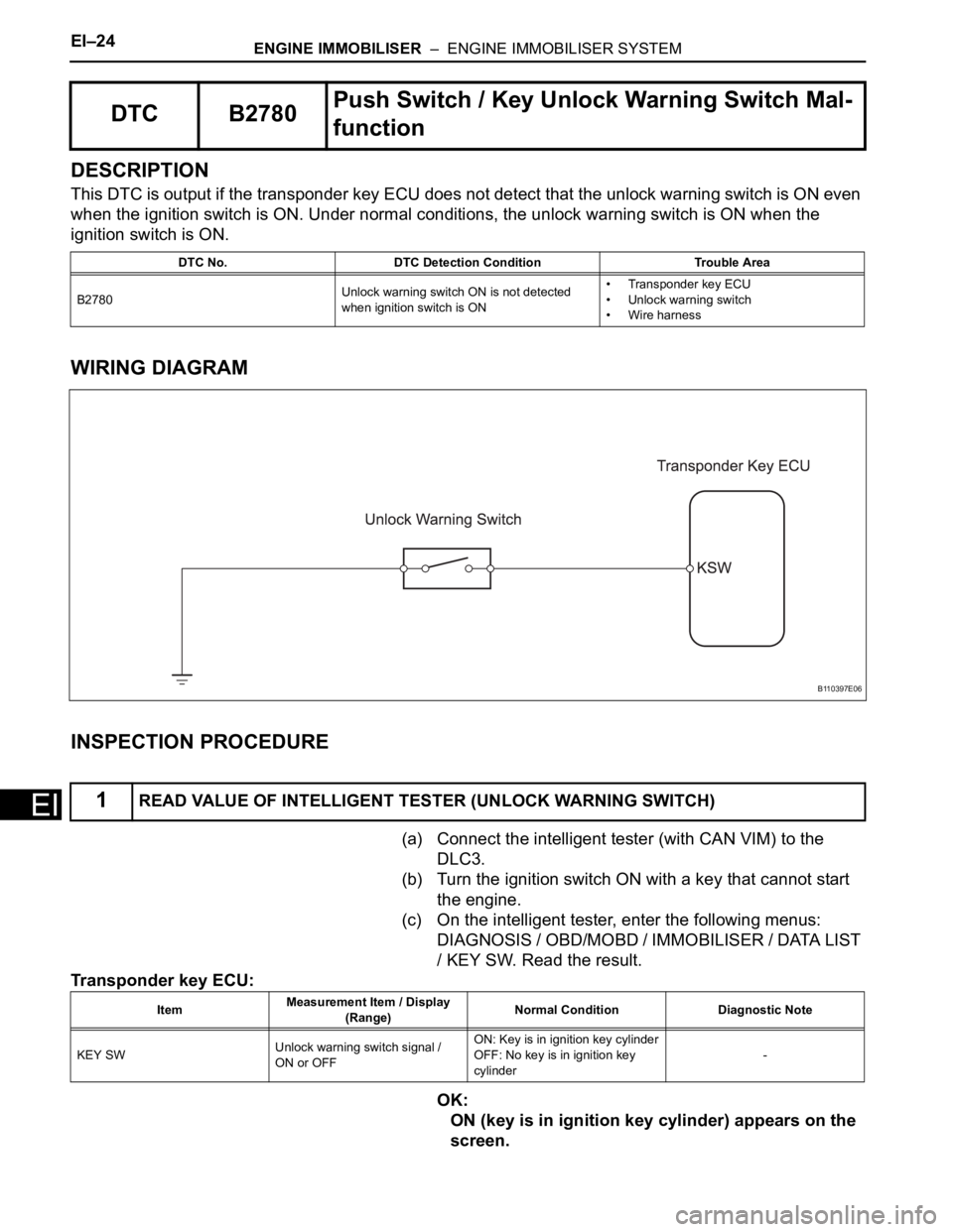
DESCRIPTION
This DTC is output if the transponder key ECU does not detect that the unlock warning switch is ON even
when the ignition switch is ON. Under normal conditions, the unlock warning switch is ON when the
ignition switch is ON.
WIRING DIAGRAM
INSPECTION PROCEDURE
(a) Connect the intelligent tester (with CAN VIM) to the
DLC3.
(b) Turn the ignition switch ON with a key that cannot start
the engine.
(c) On the intelligent tester, enter the following menus:
DIAGNOSIS / OBD/MOBD / IMMOBILISER / DATA LIST
/ KEY SW. Read the result.
Transponder key ECU:
OK:
ON (key is in ignition key cylinder) appears on the
screen.
DTC B2780Push Switch / Key Unlock Warning Switch Mal-
function
DTC No. DTC Detection Condition Trouble Area
B2780Unlock warning switch ON is not detected
when ignition switch is ON• Transponder key ECU
• Unlock warning switch
• Wire harness
1READ VALUE OF INTELLIGENT TESTER (UNLOCK WARNING SWITCH)
B110397E06
ItemMeasurement Item / Display
(Range)Normal Condition Diagnostic Note
KEY SWUnlock warning switch signal /
ON or OFFON: Key is in ignition key cylinder
OFF: No key is in ignition key
cylinder-
Page 1796 of 2000
ENGINE IMMOBILISER – ENGINE IMMOBILISER SYSTEMEI–25
EI
OK
NG
(a) Remove the unlock warning switch.
(b) Measure the resistance of the switch.
Standard resistance
NG
OK
(a) Disconnect the E6 switch connector.
(b) Measure the resistance of the wire harness side
connector.
Standard resistance
NG
OKREPLACE TRANSPONDER KEY ECU
2INSPECT UNLOCK WARNING SWITCH ASSEMBLY
B115726E01
Tester Connection Condition Specified Condition
1 - 2Pushed Below 1
Not pushed 10 k or higher
REPLACE UNLOCK WARNING SWITCH
ASSEMBLY
3CHECK WIRE HARNESS (UNLOCK WARNING SWITCH - BODY GROUND)
B115727E02
Tester Connection Specified Condition
E6-2 - Body ground Below 1
REPAIR OR REPLACE HARNESS AND
CONNECTOR
Page 1797 of 2000
EI–26ENGINE IMMOBILISER – ENGINE IMMOBILISER SYSTEM
EI
(a) Disconnect the E6 switch connector.
(b) Disconnect the E46 ECU connector.
(c) Measure the resistance of the wire harness side
connectors.
Standard resistance
NG
OK
4CHECK WIRE HARNESS (UNLOCK WARNING SWITCH - TRANSPONDER KEY ECU)
B115728E02
Tester Connection Specified Condition
E6-1 - E46-3 (KSW) Below 1
E6-1 or E46-3 (KSW) - Body ground 10 k or higher
REPAIR OR REPLACE HARNESS AND
CONNECTOR
REPLACE TRANSPONDER KEY ECU
Page 1835 of 2000
CC–36CRUISE CONTROL – CRUISE CONTROL SYSTEM
CC
DESCRIPTION
Connecting terminals TC and CG of the DLC3 enables DTCs to be read through blinking patterns of the
combination meter's CRUISE main indicator light.
HINT:
When a warning light of the combination meter blinks continuously, terminal TC of the DLC3 or an ECM
may have a ground short.
WIRING DIAGRAM
TC and CG Terminal Circuit
E110507E03
Page 1837 of 2000
CRUISE CONTROL – CRUISE CONTROL MAIN SWITCHCC–37
CC
INSTALLATION
1. INSTALL CRUISE CONTROL MAIN SWITCH
(a) Install the switch with the 2 screws.
Torque: 1.7 to 3.0 N*m (17.34 to 30.60 kgf*cm,
15.04 to 26.55 in.*lbf)
(b) Connect the connector.
2. INSTALL STEERING PAD ASSEMBLY (See page RS-
336)
3. CONNECT CABLE TO NEGATIVE BATTERY
TERMINAL
4. CHECK SRS WARNING LIGHT
(a) Check the SRS warning light (see page RS-37).
B127290E08
Page 1847 of 2000

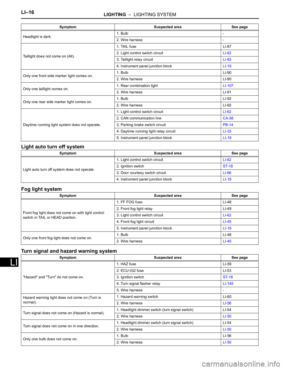
LI–16LIGHTING – LIGHTING SYSTEM
LI
Light auto turn off system
Fog light system
Turn signal and hazard warning system
Headlight is dark.1. Bulb -
2. Wire harness -
Taillight does not come on (All).1. TAIL fuse LI-87
2. Light control switch circuitLI-62
3. Taillight relay circuitLI-83
4. Instrument panel junction blockLI-19
Only one front side marker light comes on.1. Bulb LI-90
2. Wire harness LI-90
Only one taillight comes on.1. Rear combination lightLI-107
2. Wire harness LI-91
Only one rear side marker light comes on.1. Bulb LI-92
2. Wire harness LI-92
Daytime running light system does not operate.1. Light control switch circuitLI-62
2. CAN communication lineCA-58
3. Parking brake switch circuitPB-14
4. Daytime running light relay circuitLI-33
5. Instrument panel junction blockLI-19
Symptom Suspected area See page
Light auto turn off system does not operate.1. Light control switch circuitLI-62
2. Ignition switchST-18
3. Door courtesy switch circuitLI-66
4. Instrument panel junction blockLI-19
Symptom Suspected area See page
Front fog light does not come on with light control
switch in TAIL or HEAD position.1. FF FOG fuse LI-48
2. Front fog light relay LI-49
3. Light control switch circuitLI-62
4. Front fog light circuitLI-45
5. Instrument panel junction blockLI-19
Only one front fog light does not come on.1. Bulb LI-48
2. Wire harnessLI-45
Symptom Suspected area See page
"Hazard" and "Turn" do not come on.1. HAZ fuse LI-59
2. ECU-IG2 fuse LI-53
3. Ignition switchST-18
4. Turn signal flasher relayLI-145
5. Wire harness -
Hazard warning light does not come on (Turn is
normal).1. Hazard warning switch LI-60
2. Wire harnessLI-56
Turn signal does not come on (Hazard is normal).1. Headlight dimmer switch (turn signal switch) LI-54
2. Wire harnessLI-50
Turn signal does not come on in one direction.1. Headlight dimmer switch (turn signal switch) LI-54
2. Wire harnessLI-50
Only one bulb does not come on.1. Bulb LI-56
2. Wire harnessLI-50 Symptom Suspected area See page
Page 1850 of 2000

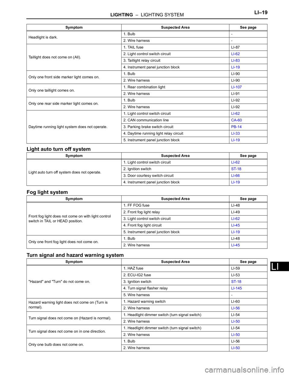
LIGHTING – LIGHTING SYSTEMLI–19
LI
Light auto turn off system
Fog light system
Turn signal and hazard warning system
Headlight is dark.1. Bulb -
2. Wire harness -
Taillight does not come on (All).1. TAIL fuse LI-87
2. Light control switch circuitLI-62
3. Taillight relay circuitLI-83
4. Instrument panel junction blockLI-19
Only one front side marker light comes on.1. Bulb LI-90
2. Wire harness LI-90
Only one taillight comes on.1. Rear combination lightLI-107
2. Wire harness LI-91
Only one rear side marker light comes on.1. Bulb LI-92
2. Wire harness LI-92
Daytime running light system does not operate.1. Light control switch circuitLI-62
2. CAN communication lineCA-60
3. Parking brake switch circuitPB-14
4. Daytime running light relay circuitLI-33
5. Instrument panel junction blockLI-19
Symptom Suspected Area See page
Light auto turn off system does not operate.1. Light control switch circuitLI-62
2. Ignition switchST-18
3. Door courtesy switch circuitLI-66
4. Instrument panel junction blockLI-19
Symptom Suspected Area See page
Front fog light does not come on with light control
switch in TAIL or HEAD position.1. FF FOG fuse LI-48
2. Front fog light relay LI-49
3. Light control switch circuitLI-62
4. Front fog light circuitLI-45
5. Instrument panel junction blockLI-19
Only one front fog light does not come on.1. Bulb LI-48
2. Wire harnessLI-45
Symptom Suspected Area See page
"Hazard" and "Turn" do not come on.1. HAZ fuse LI-59
2. ECU-IG2 fuse LI-53
3. Ignition switchST-18
4. Turn signal flasher relayLI-145
5. Wire harness -
Hazard warning light does not come on (Turn is
normal).1. Hazard warning switch LI-60
2. Wire harnessLI-56
Turn signal does not come on (Hazard is normal).1. Headlight dimmer switch (turn signal switch) LI-54
2. Wire harnessLI-50
Turn signal does not come on in one direction.1. Headlight dimmer switch (turn signal switch) LI-54
2. Wire harnessLI-50
Only one bulb does not come on.1. Bulb LI-56
2. Wire harnessLI-50 Symptom Suspected Area See page
Page 1886 of 2000
LI–136LIGHTING – HEADLIGHT DIMMER SWITCH
LI
(b) Install the headlight dimmer switch with the clamp.
(c) Connect the connector.
2. INSTALL WIPER AND WASHER SWITCH ASSEMBLY
(See page WW-29)
3. INSTALL SPIRAL CABLE SUB-ASSEMBLY (See page
RS-347)
4. INSTALL STEERING COLUMN COVER (See page SR-
20)
5. INSTALL STEERING WHEEL ASSEMBLY (See page
SR-21)
6. PLACE FRONT WHEELS FACING STRAIGHT AHEAD
7. INSPECT STEERING WHEEL CENTER POINT
8. INSTALL STEERING PAD ASSEMBLY (See page RS-
336)
9. CONNECT CABLE TO NEGATIVE BATTERY
TERMINAL
10. INSPECT STEERING PAD ASSEMBLY (See page RS-
337)
11. CHECK SRS WARNING LIGHT
(a) Check the SRS warning light (see page RS-337).
B135620
B088653